
ABSTRACT
The treated wastewater provides environmental benefits by providing additional nonconventional source of water which helps to overcome water scarcity challenge. Moreover, it decreases discharged pollution and reduces adverse impacts on human health. The objective of this study is to evaluate wastewater treatment technologies which are Conventional Activated Sludge (CAS) and Membrane Bioreactor (MBR). The project emphasises on characterizing the strength of raw sewage, compare the quality of treated effluent to Standards and evaluate the removal performance. The results showed that raw sewage of CAS can be categorized as high strength concentrate but as medium strength concentrate by MBR. Both technologies produce very good quality of treated effluent since most parameters showed compliance with standard. The removal efficiency achieved at CAS for TSS, TN and BOD are 97%, 57% and 98% respectively, while that accomplished at MBR are 98%, 82% and 98% respectively. However, the removed amounts of the TSS, TN and BOD in CAS were 437, 40 and 442 kg/1000 m3 respectively compared to 147, 37 and 206 kg/1000 m3 respectively, for MBR. The CAS system presented superior performance to the MBR in almost all of the investigated criteria, except for nitrogen removal. Further investigation is needed to ensure that the MBR process is flexible enough to achieve similar volumetric removal as the CAS system under similar operating conditions, so that both technologies can be considered as solutions contributing towards sustainable water management.
1 Introduction
The control of water supply and water recycling provides tremendous environmental benefits. By providing an additional source of nonconventional water, wastewater treatment can help to overcome water scarcity challenge in the arid and semi-arid region (Zanetti et al., 2010). Wastewater recycling is a sustainable approach and can be considered as cost-effective in the long term. In addition, the treatment of wastewater supports a decrease in the pollution of wastewater discharges and benefits human health (Baawain et al., 2020, 2019a, 2019b; Iglesias et al., 2010).
Activated sludge (CAS) is a conventional biological wastewater-treatment process. It has been used extensively in its original form, as well as with many modifications. There are three basic components in the activated sludge process: a biological reactor in which the microorganisms responsible for treatment are kept in suspension and aerated; a clarifier for liquid solids separation; and a recycle system for returning some of the solids removed from the liquid-solids separation unit back to the reactor (Li, 2013). Activated sludge is a widely used biological treatment process. It produces a good quality effluent but is more sensitive to shock loads and toxic matter. The system is associated with biomass instability issues such as sludge bulking. The CAS process cannot remove all the contaminants up to the desired level. Therefore, subsequent chemical or physical treatment, such as chlorination and/or UV ray treatment are required. Such chemical treatments impose risks and threats to the environment and public health as it discharges chemicals and chemicals by-products through effluent into aquatic systems (Chitrakar et al., 2019; Al-Mamun, 2017; Baawain et al., 2017; Zanetti et al., 2010). To improve the effluent quality before final disposal, membrane-based technology can be better alternatives for removing tiny solid particles and pathogenic microbes without any usages of eco-threatening chemical treatment steps (chlorination or ozonation) (Jafary et al., 2018, 2020a, 2020b; Al Lawati et al., 2019).
The membrane technology is commonly known as Membrane Bioreactor (MBR) technology. It is the combination of activated sludge treatment together with a separation of the biological sludge by micro- or ultra-filtration membranes with pore size of typically 10 nm to 0.5μm to produce the particle free effluent. The latter step replaces the final clarifiers and sand filter used in conventional activated sludge treatment which achieves solid separation by gravity only. The physical barrier imposed by the membrane system provides complete disinfection of the treated effluent (Le-Clech et al., 2006). The idea of replacing the settling tank of the conventional activated sludge process was attractive but difficult to justify the use of such a process due to the high cost of membranes, low profit value of the product and the rapid loss of performance because of membrane fouling. However, recent studies have provided some insight on comparing the CAS to the MBR process in a variety of municipal sewage (De Luca et al. 2013; Liu et al., 2009; Zanetti et al., 2010).
Over the last decades, MBR has proven to be a valuable alternative for CAS (Van den Broeck et al., 2010). Mainly because the MBR has some major advantages than that of the CAS, including space reduction, superior removal performance, sludge reduction, and ease of maintenance (Drews, 2010; Jeison et al., 2007; Judd, 2010; Tewari et al., 2010). However, MBR possesses a key drawback, i.e., membrane fouling that leads to increase trans-membrane pressure and influence the removal efficiencies and nitrous oxide emission (Van den Broeck et al., 2012). For this reason, an upgraded version of MBR with microbial fuel cell (MFC) for sewage treatment is quite essential for combined removal of organics and nitrogen, and recovery of electrical energy (Ryue et al., 2020; Lefebvre et al., 2008a, 2008b, 2009, 2010; Al-Mamun et al., 2015). However, this up-gradation can be feasible only by exploring the cost-effective materials and appropriate reactor designs with combined MBR-MFC system (Al-Mamun et al., 2016, 2017a, 2017b; Chung et al., 2020).
In recent decades, advanced wastewater treatment technologies, such as MBR, are of particular attention, because of the thorough removal efficiency of the suspended and dissolved chemical and biological components from wastewater (Petrović et al., 2003; Barua et al., 2018, 2019). Therefore, in this work, a case study of municipal wastewater treatment comparing the MBR, and CAS technology is carried out, to gain understanding of removal efficiencies of organic matter, chemical constituents and microbial pollutants from a wide range of full-scale treatment plant. The samples were collected at three locations which were influent raw sewage (RS), biological aeration tank and treated effluent. The emphases of the research project are to characterize the strength of influent RS, distinguish the concentration load in the biological treatment tank, calculate the removal performance of each parameter, and compare the quality of treated effluent to the ministry of environment and climate affairs (MECA) standard specifications in Muscat, Sultanate of Oman. This allows a technological recommendation for the optimization of sewage treatment plant (STP) in the municipal sewage treatment plant.
2 Materials and method
2.1 Process description of old Al Ansab Sewage Treatment Plant
The old Al Ansab Sewage Treatment Plant (STP) was designed to treat annual average flow of 12,000 m3/day with a peak flow of up to 24,000 m3/day. The old Al Ansab STP was commissioned in 1990 and then handed to Haya Water in 2006. The plant was designed to treat the wastewater by Conventional Activated Sludge process (CAS) as an extended aeration type. The process designed to operate at solids retention time (SRT) of 21 days. The treated effluent quality is produced to meet standard B of MECA MD 145/93. Since 2010 the plant design capacity was reduced to 8,000 m3/d after converting stream 1 to balancing tank for the new Ansab and gradually the flow to old Ansab was reduced by diverting flow from tankers to the new Ansab STP. The plant of old Al Ansab consists of five main units: Tanker Discharge Area, Pre-treatment facilities, Secondary Biological Treatment, Filtration, and Chlorination.
2.1.1 Tanker discharge area
Provision is made for thirty tankers to discharge simultaneously through standpipes fitted with locks isolating. The tankers are able to park diagonally for discharging and leave the discharging bays without reversing. The discharge area is built to suitable gradients and provided with suitable drainage facilities and hydrants to wash down the tanker spillages.
2.1.2 Pre-treatment facilities
The preliminary unit is used to remove coarse particles by screening. One mechanical screen and screw conveyor for refuse removal are provided on the main septic channel to the works located in an enclosed room.
2.1.3 Secondary biological treatment
The pretreated influent is distributed into three aeration tanks, where surface aerators are installed to introduce the necessary oxygen to form the activated sludge and to maintain this sludge in suspension to optimize the mixing with the incoming waste. Nitrification and denitrification reactions are achieved by installing three submersible mixers. After the necessary retention time, the mixed activated sludge liquor leaves the aerations tank over the overflow weirs and drains off to the two clarifiers where the activated sludge settles and the clarified water flows to the next step of the treatment in this case, the filters. The clarified water from the two clarifiers is collected in the clarifier pit. One part of the settled sludge is recirculated at the top of aeration tank to maintain the adequate sludge concentration in the aeration tank. While the other part of the produced excess sludge is drained off to the thickener for dewatering in the new Al Ansab STP.
2.1.4 Filtration
The water from the clarifiers is flushed by gravity to four mixed media filter. Each filter consists of a mixed media using sand and hydroantracite. The granulometry of sand is between 0.7-1.25 mm with 0.5 m height and for hydroantracite 1.4-2.5 mm with 0.8 m height. Each sand filter is designed for 7 m length, 3 m width and 21 m2 surface area. Backwashing of filter media is required to maintain healthy and efficient media for filtration. During the backwashing, the filter media is rigorously agitated to move the retained matter from the filter mass.
2.1.5 Chlorination
The final effluent will be disinfected by chlorine gas before discharged to the distribution network. The chlorination unit includes eight chlorine containers installed in the chlorine dosing room. The leakage of chlorine is controlled and monitored by detector that alert at four ppm of chlorine gas.
2.2 Process description of new Al Ansab Sewage Treatment Plant
The new Al Ansab Sewage treatment Plant (STP) is an integral part of the Muscat Wastewater Scheme Project with a plant average capacity of 55,000 m3/day. Al Ansab STP was commissioned in 2010 to serves the Bawsher Catchment. It has the second largest population of the Muscat Governorate after A’Seeb with total population was estimated to be 192,235 in the 2010 census. The treatment process of the new Al Ansab STP consists of six main units which are preliminary treatment, biological treatment, solids separation, treated effluent storage, sludge dewatering, chemical storage & dosing and odor control system. Each unit includes one or more-unit operation as illustrated in the process flowchart. Al-Ansab plant is based on the Membrane Bioreactor (MBR) Technology which is one of the latest technologies in the wastewater treatment industry. Al-Ansab plant is one of the largest of biological treatment plant worldwide using the MBR technology. This process requires a considerably reduced footprint than conventional schemes and has the advantage of producing high quality treated water.
2.2.1 Collection system
Wastewater from Bawsher area is transported to the main sewage lift station called Azaiba Central Pump Station (CPS) by means of pipes and channels. Sewers are constructed sloping downwards so that wastewater flows towards the CPS. The collected raw sewage is then pumped through a 1200 mm diameter main pipeline to the Al Ansab sewage treatment plant with the capacity of 30,000 m3/d. The balance of sewage capacity of 25,000 m3/d is received by tanker facilities. The combined flow is transferred to pre-aeration tanks where the raw sewage is aerated to reduce septicity, to reduce odor generation potential and to prevent settling of solids in sewage. In addition, Caustic soda or sodium hydroxide (NaOH) dosing system is added for adjusting the pH of the incoming raw sewage. Two pre-aeration tanks are provided for the aeration of the sewage using coarse bubble diffusers.
2.2.2 Pre-treatment unit
The wastewater is passed through a physical mechanical separation to remove large debris such as glass, rags, and stones. Its two main units are Screening and Grit Removal. Screening protects the downstream units of the treatment plant from obstructions caused by the larger debris and improves the efficiency of the operations in the later stages. Three 3mm drum screens are provided for fine screening. The screening chamber consists of vertical stainless-steel screens at an angle 30 degrees to the horizontal. Stainless steel is used to prevent the screens from corrosion. They have uniform openings to retain large solids. The spacing of the screens determines the size of the particles removed.
The grit and grease removal system are provided to remove the grit and grease from the raw sewage. The grit removal consists of removing inert materials which is not biodegradable from the waste and grease removal consists of removing materials which will float and cause nuisance in the downstream process. Two units of grit and grease systems are provided for this purpose. The floated scum is separated by the grease separator from the top and collected in the scum well for further disposal.
Conveyor system is provided to collect the compacted screenings from all the drum screens and the solid grits from the grit classifier for further disposal into skip containers. This conveyor is provided with a local control panel in the field for its necessary controls.
2.2.3 Secondary biological treatment
The principle of biological treatment is to remove biological organic pollutants from the sewage. These pollutants are in the form of dissolved or soluble organics and finely insoluble and colloidal organic solids in the raw sewage. Secondary treatment in Al Ansab STP is accomplished by extended aeration process which comprises: Anoxic, Aerobic and Membrane tanks.
In the Aerobic Zone, microorganisms utilize the organic pollutants as their food. The microorganisms absorb and ingest the organic materials in the presence of oxygen and convert ammonia to nitrates through a biochemical reaction called nitrification as shown in below reaction. The nitrification is completely achieved at pH 7.5-8 and dissolved oxygen in range of 1 to 2 mg/l. The MLSS and MLVSS in the aeration zone is in range of 9500 to 10000 mg/l and 8000 to 8500 mg/l respectively. In Four aeration tanks the dissolved oxygen is injected which is necessary to keep the bacteria alive and the basin aerobic. The main source of air supply are centrifugal blowers which diffuse air (DO) through disc diffusers located at the bottom of four aeration tanks. Secondary scum is provided to collect the scum separated from the aerobic zone and transfer the scum to the scum holding tank in the Headwork area.
In the Anoxic Zone, a nitrate in wastewater is converted into nitrogen gas through a reaction called de-nitrification. This zone required free oxygen therefore submersible mixers are installed in four anoxic tanks without aeration in order to keep wastewater and the biomass mixed without settling. The plant is designed to reduce nitrates level to 8 mg/l at the outlet of biological treatment. There is a swing zone that perform both as anoxic and an aerobic stage. This zone is provided to increase the flexibility of operations and thereby achieve desired results. If during the operations, it is observed that denitrification process requires additional detention time, then air to the swing zone is stopped and this section performs like anoxic zone. Alternately, if nitrification requires more time, then the swing zone is operated as aerobic stage.
The mixed liquor is then pumped to eight Membrane Bioreactor tanks. The process couples membrane solids separation with microbial oxidation of organic and nutrient pollutants. Thus, the quality of the treated water produced from the MBR is principally dependent upon two processes; the microbial biodegradation of the organic and nutrient components present in the wastewater and the solids separation carried out by the membrane units. The MBR process uses flat sheet membrane panels housed in units and aerated by a coarse bubble system underneath each unit which is necessary to prevent rapid membrane fouling and necessary for the microbial degradation of the pollutants.
Solids are removed from the treated water by driving the mixed liquor on the outside of the membrane panels through to the inside of the panels. Permeate is transferred via a manifold through the tank wall. The liquid head above the membranes and the suction provided by the permeate pump provides the driving force needed to push the liquid through the membrane material and permeate manifold. As the membrane material provides a true barrier to the solids present in the activated sludge the plant can operate at very high MLSS concentrations. This intensification of the process reduces the tank volume necessary, enables longer sludge ages to be utilized and thus reduces excess sludge production. The needed sludge is recycled as Return Activated Sludge (RAS) to the aerobic zone. Coarse bubbles provided by air diffusers in the base section of the membrane unit ensure that a cross flow liquid velocity of 0.5 m/s is maintained between the membrane panels. Without the continuous scouring of the membrane surface during permeate production, foulants rapidly deposit on the membrane surface to form a solids layer that impedes permeate production. Three centrifugal blowers are provided for supplying air to the aerobic tanks and MBR tanks of biological treatment plant.
2.2.4 Disinfection
Primary, secondary and even tertiary treatment cannot expect to remove 100% of the incoming waste load and as a result, some organisms still remain in the waste stream. To prevent the spread of waterborne diseases and also to minimize public health problems, regulations require the destruction of pathogenic organisms in wastewaters. In Al-Ansab STP, Sodium hypochlorite (NaOCl) dosing system is provided for chlorinating permeate pumped from BTP to TE storage tank. The system consists of two pumps connected to the sodium hypochlorite storage which doses it in the permeate discharge line. Eventually, the disinfected treated effluent from the biological treatment plant is stored in TE tank to be consumed in utility water system, irrigation network and tanker loading. The residual chlorine is maintained to be 1-3 mg/l to prevent growth of algae in the TE tank, while at the boundary of the plant is monitored to be 0.3 mg/l to ensure that the water is disinfected through the distribution network.
2.2.5 Sludge dewatering unit
The excess sludge is pumped to sludge dewatering unit. The dewatering unit consists of polymer mixture, thickener, and belt press. The polymer preparation and dosing system is provided to prepare the polymer solution required for dosing in the belt filter press as coagulant. Two units of polymer preparation system is provided for this purpose. The sludge system is provided to reduce the volume of the wasted sludge in three sludge dewatering trains. The sludge loading is provided to dispose the dewatered sludge from the belt filter press and consists of two belt conveyors mounted below the belt filter press such that the dry sludge from the BFP falls on them directly through a chute. The thickened sludge discharged on the conveyor with 20% dry solid is transferred to Compost Plant.
2.2.6 Odour control unit
Hydrogen sulfide is the main cause of odor when the sewage comes from mainly households. The presence of hydrogen sulfide is caused by absence of oxygen (anaerobic condition) in long pipeline with low-speed sewage. Therefore, the received sewage has a rotten egg sensation and called septic wastewater. Thus, the Odor Control Unit in Al Ansab STP is provided to treat the hydrogen sulphide by using a Chemical Scrubber. The foul gas is collected from several sources such as: tanker discharge point, the pre-aeration tanks, screen building, grit removal unit and the dewatering building. The Chemical Scrubber uses a shower of scrubbing liquid over a bed of high surface area plastic media to promote contact within a reaction chamber. The foul air is ventilated through the plastic media in a counter-current direction to the liquid flow. The chemicals that help odor treatment are Caustic Soda and Sulphuric Acid for adjusting the pH of the scrubbing liquid at the odor control system, Hydrogen Peroxide for adjusting the ORP of the waste gas collected at the odor control unit.
2.3 Sampling procedure
The analytical results of a sample are only as accurate as the quality of the sample taken. If technique for collecting samples is poor, then no matter how accurate lab procedures are, the results will be poor. Applying a sampling procedure can reduce the chance of error and increase the accuracy of your sample results. The sample procedure consists of location selected for sampling, sample types, sample equipment and sample collection.
In this study three locations are selected to be tested are Influent Raw Sewage, Biological Aeration Tank and Treated Effluent. Influent wastewaters are preferably sampled at locations of highly turbulent flow to ensure good mixing; however, in many instances the most desirable location is not accessible. Preferable influent wastewater sampling locations include: the preliminary screened raw sewage after the Drum Screen for the old Al Ansab STP. However, the combination streams of both network and tankers are downstream of preliminary screening and aerated grit chamber for new Al Ansab STP. The second selected point is in the aeration tank for old STP, while in the new plant the average concentration of Aeration Tank and MBR Tank. Effluent samples are the third selected point which locates at downstream from sand filter before chlorination for old Al Ansab STP, as well as after MBR tank prior to discharge to disinfection for the new Al Ansab STP.
Two types of samples are taken in Al Ansab STP: Grab or Composite samples. Grab sample is collected at a particular time and place can represent only the composition of the source at that time and place. This involves manual sampling and minimal equipment but may be costly and time-consuming for routine or large-scale sampling programs. As the name implies ‘Grab samples’ are simple scoops of the wastewater being sampled and are appropriate where conditions are constant or well mixed and slow to change. This type of sample used for example for Balance Tank sampling or measuring sludge solids in the aeration basin (MLSS). Care should always be taken that a grab sample is representative of the whole and should be taken from well-mixed areas on all occasions.
In contrast the Composite sample is a sample collected over time, either by continuous sampling or by mixing discrete samples. A composite sample represents the average wastewater characteristics during the compositing period. Various methods for compositing are available and are based on either time or flow proportioning. Generally, a time composite is used in Al Ansab STP. A time composite sample consists of equal volume discrete sample aliquots collected at constant time intervals into one container. A time composite sample can be collected either manually or with an automatic sampler.
Prior to sampling, all sampling equipment as well as preparing sampling equipment and containers are determined. This attention to detail will help minimize potential errors. The equipment typically used for sampling are sample bottles of one litre or two and half litre PVC bottles to be used for all samples taken except samples taken for bacteriological, oil based or solvent analysis. In addition, sampling hand-pump with extension tube is used for depth sampling at low flow. Otherwise, a sampling beaker (250ml, 500ml or 1000ml) with screw-in extension rods to be used for depth sampling with sufficient flow. Also, Markers to be used to mark identification on sample bottles. In sample collection, the sample is collected where the wastewater is well mixed. Therefore, the sample should be collected near the centre of the flow channel, at approximately 40 to 60% of the water depth, where the turbulence is at a maximum and the possibility of solids settling is minimized.
2.4 Design characteristics
2.4.1 Plant design condition for raw sewage
The wastewater arriving at the Al Ansab STP from the sewage pumping stations and by tanker truck is mainly from domestic sources (residential, commercial, and institutional) and therefore is not expected to present unusual treatability problems. The combined influent wastewater received is expected to have the following characteristics (Table 1) when flow-proportioned composite samples are collected over a twenty-four-hour period and analysed in accordance with Standard Methods for the Examination of Water and Wastewater.
Wastewater characteristic at Al Ansab STP
| Parameter | Units | Minimum | Maximum |
|---|---|---|---|
| BOD | mg/L | 350 | 400 |
| COD | mg/L | 600 | 900 |
| TSS | mg/L | 350 | 500 |
| VSS | mg/L | 280 | 400 |
| VSS/TSS Ratio | % | 75 | 85 |
| TKN | mg/L | 50 | 70 |
| NH3-N | mg/L | 35 | 45 |
| TP | mg/L | 9 | 15 |
| Alkalinity | mg/L | 100 | 200 |
| Oil & Grease | mg/L | - | 200 |
| pH | 6.0 | 8.0 | |
| Temperature | C | 20 | 35 |
2.4.2 Plant design condition for treated water
The customer intends to reuse the treated effluent from Al Ansab STP for landscape irrigation. For this purpose, treated effluent is required to comply with effluent quality standards and regulation of Ministerial of Environment and Climate Affairs (MECA145/93).
2.5 Analytical methods
Wastewater quality indicators are laboratory tests to assess the characteristic of influent raw sewage and to ensure the compliance of treated effluent quality. In this study, critical tests selected that measure physical, chemical, and biological characteristics of the wastewater. The samples were analyzed after the collection, following standard methods (APHA, AWWA, and WEF 1999) for determination of TSS, BOD5, COD, TKN, NH4+ -N, NO3- -N, TP, FOG, and pathogens.
3 Results and discussion
The performance of the CAS and MBR systems was achieved by running different experiments before and after treatment. The results were compared with MECA standards A and B, which indicate the suitability of the final effluent for different irrigation applications.
3.1 RS characteristics
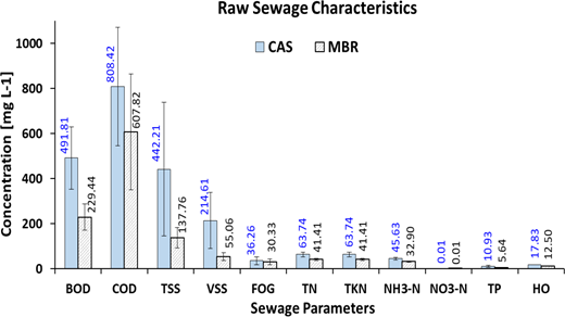
In order to quantify the performance of the CAS and MBR systems, the characteristics of RS were specified in terms of standard parameters. Figure 1 shows the average concentration of RS parameters during the study period. Generally speaking, the organic and solid contents in the sewage fed to the respective systems show specific influent sewage properties with low or even trace concentration of oil/grease, nitrogen and phosphorus compounds compared to the other parameters. As the results in Figure 1 illustrate, the average influent sewage quality of the systems is different. This is due to the fact that the MBR is fed by a large quantity of municipal wastewater through domestic sewer network; while the CAS system is fed with collected wastewater from houses, commercial and light industries through tankers. Generally, a high variability in wastewater quality for both systems was also found in previous studies (Valderrama et al. 2012; Munz et al. 2008).
Raw sewage characteristics for CAS and MBR STPs
The average values of BOD5 and COD are presented in Figure 1. According to Metcalf and Eddy (2004), the average values of BOD5 in RS is categorized as high strength for the old STP (492 mg L-1); whereas it is classified as a medium strength concentration (229 mg L-1) for the the new STP. Simultaneously, the average values of COD for old and new plant are 808 mg L-1 and 608 mg L-1, respectively. This might be related to the introduction of some industrial organic pollutants that are received by tankers at old STP (CAS). Higher concentration of degradable COD values requires a large-volume aeration basin, more oxygen transfer facilities and greater sludge production. It is also useful to know the relation between BOD5 and COD in each sampling locations to save cost and time. The RS BOD5/COD ratios for the old and for the new STPs are measured as 0.61 and 0.38, respectively. These ratios are within the typical range of 0.30 to 0.80 in RS as reported by Metcalf and Eddy (2004). Moreover, the values indicate that the RS is mainly composed of domestic wastewater without toxic elements that may kill the organic matters. Besides, in the old plant, BOD loads in the aeration tank rose slightly by 200 mg L-1 compared to those of the new plant. This is related to the design criteria of STPs, where CAS needs only a moderate quantity of bacteria to consume the organic load in higher retention time.
The solids in STPs are analyzed by using Gravimetric method. It is shown in Figure 1 that the average TSS is about 442 mg L-1 and 138 mg L-1 for the old and new STP, respectively. Based on Metcalf and Eddy (2004) study, RS of the CAS plant can be classified as high strength influent and medium strength influent for the old and new plant, respectively. That number of suspended solids could be attributed to the high load of solids received by the tankers. Average VSS concentrations in RS were 215 and 55 mg L-1 for the old and new plant, respectively. From the obtained values of TSS and VSS, the VSS/TSS ratios in influent were 0.49 and 0.40 for the old and new plants, respectively. The rest is fixed inorganic suspended solids that remain even after ignition at 550°C.
Nitrogen data can be used to evaluate the treatability of wastewater by a biological process. The results in Figure 1 show that the major parts of nitrogenous compounds are ammoniacal and only small parts are nitrate. It is worth a mention that the ammoniacal Nitrogen (NH3-N) serves as substrate for nitrification. The old STP receives denser concentration of nutrient than the new STP, which is classified as a high strength influence according to Metcalf and Eddy (2004). The TP transported to the CAS system is about double the concentration fed to the MBR. This might be due to the partial mixing of industrial wastewater with domestic wastewater in the case of CAS treatment, as the tankers partially collect industrial wastewater. Overall, the TP concentration in the MBR influent is reasonably low.
3.2 Removal performance
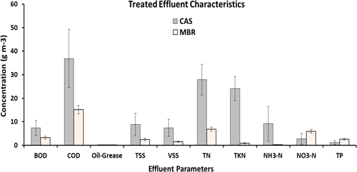
After treatment, a new set of samples was drawn from the effluent and analyzed regarding the same properties as those of the influent. The results for the effluent concentrations of all examined wastewater components are shown in Figure 2.
Treated effluent quality
The compliance of treated water is identified by comparing it with MECA standards to check the suitability of the treated wastewater in irrigation purpose or discharge to the sea. Figure 2 illustrates that the BOD5 quality of the treated effluent is 7 mg L-1 for the old plant, which is lower than that of both MECA standards. Additionally, the BOD5 value of the new plant is within the acceptable range as low as 3 mg L-1. For the COD, the treated effluents followed the MECA standard only with 37 mg L-1 and 15 mg L-1, respectively. While the MECA standards were defined as 150 mg L-1 and 200 mg L-1 for the upper and lower limits.
The quality of the TSS and VSS for the old STP was obtained after sand filter and before chlorination, while the sample was taken after filtration in the new STP. In practice the high percentage of the TSS from the CAS process is due to improper mechanical screening in the old STP. Moreover, no primary sedimentation tank was installed in both STPs that allow the heavy solids to settle down.
The concentration level of oil-grease was almost negligible from both systems. The effluent concentrations of NO3-N and TP were found in reasonable range; however, TKN and NH3-N were found above the standard limits. The concentration level of TKN at the old STP was about 24 mg L-1 which is above the limit of MECA standards A and B (5 and 10 mg L-1, respectively). The concentration of NH3-N exceeded the standard value which is the same as TKN. This could be due to insufficient amount of dissolved oxygen supplied by the very old aerators as well as lack of adequate air diffusers installed at the bottom of the tank.
On the other hand, for the new STP, the results illustrated that TKN, NH3-N, and NO3–N are within the standards and the measured values are 0.86, 0.26, and 5.96 mg L-1, accordingly. The concentration limits of TN for both processes are obtained satisfactory. Subsequently the removal efficiency of the wastewater components is discussed separately as it allows a comparison of the two treatment systems.
3.3 Removal efficiency
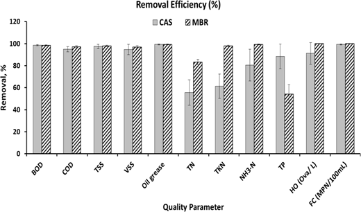
The results in Figure 3 suggest that organics in terms of BOD5 and COD were removed from >95% in the MBR as well as the CAS treatment system. Particulate matter in the form of TSS was removed up to 98% in the MBR and 97% in the CAS system. Regarding the VSS, the MBR performed slightly better as up to 96.8% was removed in the MBR compared to 94.7% in the CAS system. Oils and greases were removed from 99% in both treatment plants.
Performance removal efficiency
It is clear that the removal efficiency of TN at the new STP is 83%, which is much better compared to the old STP of 55%. Moreover, TKN and NH3-N removal were >98%. Regarding the nitrogen removal, the MBR was able to remove up to 99% of NH3-N and approximately 83% of the TN, where the CAS was only able to remove approximately 55% of the total nitrogen. Hence, the MBR system showed better performance, which could be due to the fact that the aged aeration equipment in the CAS system supplying oxygen to nitrifying microbes does not meet the performance criteria to achieve full nitrification. However, in the MBR system nitrate compounds form probably due to incomplete denitrification, which effectively increases the concentration of nitrate. An additional denitrification step would be necessary for complete nitrate removal. In the CAS system less nitrogenous compounds, i.e. ammonia and organic nitrogen, were removed and therefore less nitrate formed because of relatively poor aeration nozzles. The results of the nitrogen and ammonia removal from the MBR system are similar to reported studies for municipal wastewater (Côté et al. 1997; Mohammed et al. 2008), where González et al. (2007) found similar results in a poorly performing CAS system in terms of ammonia removal. The remaining nitrogen (organic nitrogen) has a complex structure that makes it difficult to degrade. The unacceptable removal efficiency percentage of nitrogen in the old plant has a negative impact on system performance by growing algae inside the facilities.
Additionally, the removal amount of TP by CAS (88%) was higher than the MBR (54%), respectively. The removal of phosphorus as displayed in Figure 3 showed that approximately 54% of phosphorus were removed by MBR, whereas the CAS treatment removed 88% of the TP from the influent. In both cases the effluent concentration is below the limits set of the Oman MECA standards, deeming the treated effluent suitable for irrigation use.
Helminths ova (HO) were completely removed by using the MBR technology, because the membrane holding back solids and microbes. However, the CAS system removed the HO to approximately 91% by settling. Fecal coliforms (FC) were removed up to 99.99% in the MBR and up to 99.25% in the CAS STP. These results suggest that in both cases additional disinfection unit is required. The removal performance of biological pollutant using the MBR technology is more reliable than that of membrane filtration because it removes particulate matter more reliably than a settling basin (De Luca et al., 2013). The removal performance of Fecal Coliform (FC) is exceptional for both STPs. This fact is attributed to the smaller pore size of membrane sheets that they don’t allow the bacteria to exist with size greater than 0.04 µm. On the other hand, the discharged FC at the old STP is in the range of thousands most probable number (MPN) per 100 mL, but it is very small compared to the inlet Coliform in RS. This resultants bacteria before disinfection by Sodium Hypochlorite, are decreased to less than 1000 MPN/100 mL as per standard B and less than 200 MPN per 100 mL as standard A of MECA before discharging to network. Since the Helminthes eggs are very critical, it is necessary to calculate its removal efficiency. Thus, Figure 3 illustrates the removal efficiency as 96.9% for Conventional plant and 100% for the new MBR Technology over the testing period. The resulted viable Helminthes Ova from the old Al Ansab STP might be due to large openings of sand filter. Overall, both systems show a comparably high removal efficiency for the same treatment time, where on average the MBR system performed slightly better than the CAS system.
3.4 Removal amount
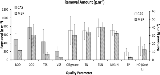
In terms of volumetric removal of the above-described substances, Figure 4 shows the removed amount instead of the percentage values. The data from the results in this figure suggests that the CAS system presented superior performance to the MBR in almost all of the investigated criteria, except for nitrogen removal as in this case the CAS system underperformed due to the unsuitable aeration nozzles. To achieve full comparability of the two treatment process plants further investigation is necessary to examine if the MBR performs equally under the same conditions of the CAS system.
Mass reduction in (g/m3)
4 Conclusions
A study of STPs for treatment of municipal wastewater was conducted by comparing a plant using a CAS system with one using MBR technology in Muscat, Sultanate of Oman. The MBR system was connected to a municipal wastewater pipeline, while the CAS system receives domestic wastewater from septic tanks and light industrial wastewater through tankers. The analysis of the influent sewage of the two plants revealed a difference in wastewater properties as all the examined criteria of the wastewater influent to the CAS system occurred in higher concentration. On average, the MBR system removed up to 97% and the CAS system up to 95% of organics in terms of COD. This leads to a conclusion that both processes perform stably and are robust with varying influent wastewater organic quality. Further, the removal performance of the MBR regarding nitrogenous compounds was found superior to the investigated CAS system. Regarding helminths ova and fecal coliforms, the MBR technology is to be preferred due to its solid retention capabilities, which decreases the necessity of additional strong disinfection effluent treatment. On the other hand, the data in terms of removal amounts (i.e. mass of contaminant per volume of wastewater) indicated that the CAS system presented superior performance to the MBR in almost all of the investigated criteria, except for nitrogen removal Therefore, further investigation is needed to ensure that the MBR process is flexible enough to achieve similar volumetric removal as the CAS system under similar operating conditions.
5 Acknowledgements
The research was supported by Sultan Qaboos University through The Research Council fund no RC/RG/ENG/CAED/19/01. The Author would like to thank the Research and Development Team at Haya Water Company. As part of the project, Haya Water Central Lab was supported to collect and analyze the samples, which are appreciated.