This study aims to extract a reduced order model based on the Cauer ladder network (CLN) method from a partial element equivalent circuit (PEEC) formulation of the eddy current problem in parallel conductors. The obtained equivalent circuit can then be effectively used for time domain simulations.
The PEEC formulation has been written as a first-order linear dynamic system, and the CLN algorithm has been applied to extract the reduced-order model. The numerical results of the reduced order model have been then compared with the reference results obtained both with the finite element method (FEM) and the PEEC method for a canonical test case of two rectangular conductors.
The Cauer ladder network representation of the eddy current fields is proved to be accurate enough in frequency and in time domains, provided that a sufficient number of the equivalent circuit stages is considered.
The CLN method has already been applied in the past to FEM for eddy current problems. In this work, the CLN has been applied to the PEEC method for the first time.
1. Introduction
Among the existing computational methods for solving eddy-current problems, the partial element equivalent circuit (PEEC) method is gaining importance, due to the possibility of coupling it with circuit models (Ruehli et al., 2017; Nguyen et al., 2016).
The Cauer ladder network (CLN) method is a model order reduction approach that allows obtaining an equivalent Cauer circuit (Shindo et al., 2017). This method has been introduced and developed for finite element formulations (Kameari et al., 2017). Many applications of the CLN have been proposed in recent years. In particular, the CLN equivalent representation can be used to compute the earth return impedance of an high voltage direct current (HVDC) (Tang et al., 2025); to model the electromagnetic behavior of a printed circuit board to efficiently design the power converter operating at high switching frequencies (Henneron et al., 2025); to present the connection between CLN and the proper generalized decomposition with a novel double vector potential formulation (Köster et al., 2021).
In this paper, the application of the CLN method to a PEEC formulation is proposed for the first time. It is shown that the structure of PEEC matrices exhibits important advantages over FEM matrices when applying the CLN method.
Magneto-quasistatic conditions are assumed when deriving the PEEC formulation, neglecting wave propagation effects. This hypothesis can be considered valid up to 500 MHz so that the corresponding wavelength is approximately equal to ten times the distance between the centers of the two conductors, that is a characteristic size of the problem. In these conditions, capacitive and wave propagation effects can be safely neglected.
To explain the application of the CLN method to a magneto-quasistatic PEEC formulation, we refer here to a very simple test case of two parallel rectangular conductors (Morisco et al., 2019). The case of more complex geometries does not require conceptual modifications.
Once the CLN circuit has been obtained, the results both in time and frequency domains are compared with PEEC and finite element method (FEM) simulations (COMSOL AB, 2024), where the latter are taken as reference.
2. PEEC formulation
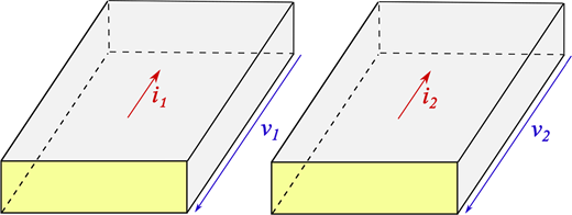
Consider two parallel rectangular conductors of width w and thickness t shown in Figure 1 carrying two opposite time-harmonic excitation currents .
The conductors are subdivided into n smaller rectangular sub-conductors (Morisco et al., 2019). The dimensions of each sub-conductor, , are chosen smaller than the skin depth () to assume the current density inside it as uniform (Ruehli et al., 2017).
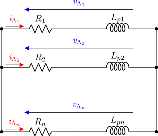
Each sub-conductor is modeled as a series connection of its DC resistance and its partial inductance (Morisco et al., 2019). The conductors can be represented as a parallel network of sub-conductors as reported in Figure 2.
The resistance and inductance matrices are given by the following:
The following complex symmetric impedance matrix thus describes the complete electromagnetic coupling of the system:
The relationship between sub-conductor voltages and currents reads:
where is the vector of sub-conductor voltages and is the vector of sub-conductor currents.
A connectivity matrix is introduced, in which each row corresponds to a sub-conductor and each column to a conductor. Its elements are given by the following:
Each row of matrix contains exactly one element equal to 1, while the other is zero.
The symmetric terminal admittance matrix can be then written as follows:
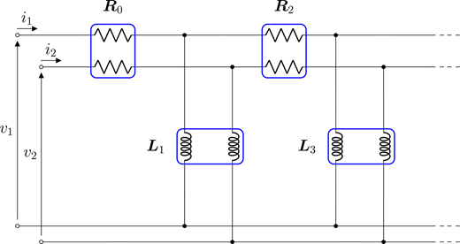
where, referring to Figure 3, its elements are defined as follows:
From equation (6), the terminal impedance matrix of the conductors is obtained as follows:
The terminal impedance of each of the two conductors is then defined as follows:
Equation (6) represents the transfer function of the following linear time-invariant system:
where and are, respectively, the input and output vectors of the system.
3. CLN formulation
Equations (11) and (12) describe the full-order model obtained from the PEEC formulation. In the following, a reduced-order model is obtained by applying the CLN method to this PEEC formulation.
Transfer function (6) can be rewritten as follows:
where , and .
Algorithm 1, applied to the full-order transfer function (13), allows writing the reduced-order system by computing matrices and , which are orthogonal with respect to the and inner products, respectively (Hiruma and Igarashi, 2020). The coefficient matrices () are defined as follows:
where is the Kronecker delta.
Since matrices are also positive-definite, the obtained coefficient matrices are positive-definite so that the obtained reduced-order Cauer circuit is passive.
Coefficient matrices correspond to the coefficients of the continued fraction expansion of transfer function (13). In fact, its Taylor series expansion around is given by the following:
where , are referred to as the moments.
Setting in Algorithm 1 the initial matrix , it is possible to construct the set of matrices orthogonal with respect to inner product, i.e. the orthogonal matrices are -orthogonal to each other (Hiruma, 2021). A three-term recurrence relation is satisfied:
where . Equation (17) can be written in a compact matrix form as follows:
where and is a tridiagonal matrix defined as follows:
Using (14, 15) and (18), it can be shown that:
where
The moments () are expressed as follows:
where
Therefore, the partial realization of the transfer function becomes:
In the CLN method, the approximation of the original transfer function is represented by a continued fraction. It can be shown that:
where and denotes:
Substituting (22) in (21) results in:
Equation (24) is the transfer function of the reduced-order system written as follows:
where:
The system given by equations (25) and (26) describes the reduced-order model. In particular, equation (25) corresponds to the KVL of the equivalent Cauer circuit, and the transfer function of the reduced-order system corresponds to the admittance of the Cauer circuit. It can be written as follows:
where the inverse of the even coefficient matrices represent the resistive component of the Cauer circuit, and the odd coefficient matrices, represent the inductive component of the Cauer circuit and , for :
It can be concluded that the continued fraction expansion of the reduced-order transfer function can be directly obtained from Algorithm 1. The corresponding equivalent Cauer circuit is shown in Figure 4 (Matsuo et al., 2020).
4. Numerical results
Considering , the values of resistances and inductances of the reduced order Cauer circuit of Figure 4 are reported, respectively, in Tables 1 and 2.
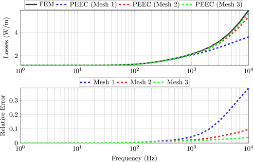
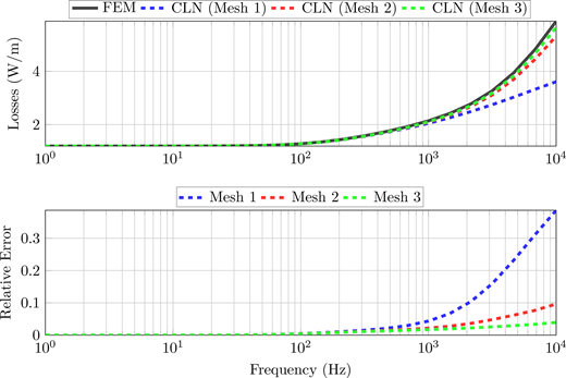
Per-unit-length power losses of the system are computed for both the PEEC and the CLN formulation with , for frequencies up to 10 kHz, considering three different meshings of the conductors reported in Table 3.
The resulting values are reported in Figures 5 and 6, where they are also compared with the FEM results obtained using COMSOL.
To correctly apply the CLN to the PEEC formulation, the PEEC must provide accurate results. In fact, if the CLN method is applied to PEEC without using a sufficiently refined mesh of the conductors, it cannot guarantee an accurate representation of the reference solution, as shown in Figures 5 and 6. For this reason, in the following computations, mesh 3 will be adopted.
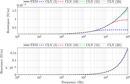
The ladder elements of the CLN circuit represent the frequency resistive and inductive effects as can be noted in Figure 7. Here, the per-unit length terminal resistance and reactance of the conductors are shown.
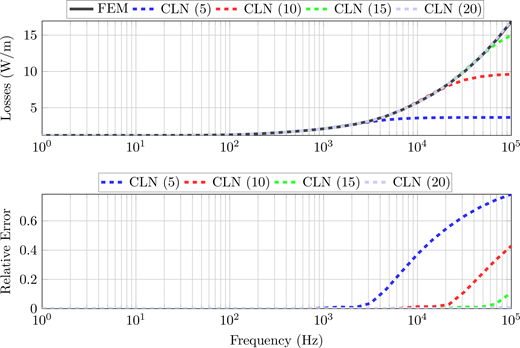
Once a good meshing of the conductors is provided, the relationship between the number of stages of the reduced equivalent circuit and the accuracy of the CLN formulation is analyzed. In particular, the per-unit-length power losses computed with PEEC are compared with those obtained using the CLN formulation, considering different numbers of stages (Figure 8).
Computational times versus number of stages q of the reduced equivalent circuit are reported in Table 4. Note that the CLN method with 20 stages is almost 20 times faster than the full order PEEC formulation when computing the terminal impedance.
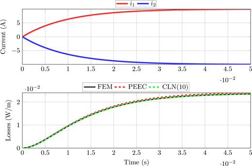
As an example of a time-domain simulation, the Joule losses are computed when the two conductors are excited by the following two opposite currents:
where and .
5. Conclusion
The CLN method has been applied for the first time to a PEEC formulation in an efficient way, also thanks to the diagonal structure of the matrix that can be easily inverted, as required by the algorithm. The obtained reduced order model maintains the same advantages of the PEEC method, i.e. only active conductors must be discretized and open boundary problems are well treated.
For wide-band frequency domain analysis, the CLN representation can reduce computational times compared to the full-order PEEC and FEM methods. Furthermore, good accuracy can also be obtained in a time domain analysis.
The CLN representation of the eddy current fields extracted from a proper PEEC formulation has been shown to be accurate enough, provided that a sufficient number of equivalent circuit stages are considered. As expected, the accuracy of the CLN reduced-order model extracted from PEEC decreases as the working frequency increases.