
This paper aims to elaborate the method and algorithm for the analysis of the influence of temperature on back electromotive force (BEMF) waveforms in a line start permanent magnet synchronous motor (LSPMSM).
The paper presents a finite element analysis of temperature influence on BEMF and back electromotive coefficient in a LSPMSM. In this paper, a two-dimensional field model of coupled electromagnetic and thermal phenomena in the LSPMSM was presented. The influence of temperature on magnetic properties of the permanent magnets as well as on electric and thermal properties of the materials has been taken into account. Simulation results have been compared to measurements. The selected results have been presented and discussed.
The simulations results are compared with measurements to confirm the adequacy of this approach to the analysis of coupled electromagnetic-thermal problems.
The paper offers appropriate author’s software for the transient and steady-state analysis of coupled electromagnetic and thermal problems in LSPMS motor.
1. Introduction
Line start permanent magnet synchronous motors (LSPMSMs) are characterized by a high value of power density, compact design as well as a high power factor and high efficiency. For this reason, they are commonly used in industrial applications replacing classic induction motors (Ganesan and Chokkalingam, 2019; Pałka et al., 2019). When designing new LSPMSM constructions, sub-assemblies of classic induction motors are often used (Jedryczka et al., 2014; Baranski et al., 2017; Baranski et al., 2020), and designing comes down to developing a new structure of a rotor. When designing and optimizing a rotor with permanent magnets and a starting cage, it is important to choose the right shape and arrangement of magnets and cage winding bars (Yang et al., 2008; Knypiński, 2017). The aim is to achieve the highest efficiency and power factor while ensuring requirements for starting parameters (Knypiński et al., 2017). In addition, due to the minimization of electromagnetic torque ripples, the aim is to obtain the magnetic field distribution in the air gap and the e(t) waveforms of back electromotive force (BEMF) with the lowest content of higher harmonics (Jedryczka et al., 2014; Lin et al., 2018).
Long-term operation of the motor at rated load conditions, its frequently repeated starting processes and direct reversing as well as its work at elevated ambient temperature can cause a large increase in the temperature of magnets and as a consequence, lead to:
reduction of the voltage induced in the windings with increasing temperature, reduction of the electromagnetic torque; or
a partial demagnetization of the magnets and permanent deterioration of the motor’s functional parameters (McFarland and Jahns, 2012; Hamidizadeh et al., 2016; Baranski et al., 2017; Chen et al., 2017).
A benchmark of the effect of temperature on the value of induced voltage can be the change of the kE BEMF coefficient occurring with the change of temperature. This coefficient determines the value of the voltage induced in the winding per rotating of the rotor (Drury et al., 2010; Ozturk et al., 2010; Ma and Qi, 2018). The kE coefficient is often applied in classical circuit models of permanent magnet machines. It is used, among other things, for the analysis and design of drive systems and the control or monitoring of their state (Ramakrishnan et al., 2009; Ozturk et al., 2010; Ma and Qi, 2018). For example, in permanent magnet synchronous motor drives, accurate knowledge of machine parameters like the kE coefficient has the advantage of controlling and/or monitoring its condition. Disregarding the influence of temperature on the EMF value in these models and thus also on the kE coefficient may lead to obtaining less reliable calculation results.
The decrease of the magnetic flux generated in the machine by the magnets that occurs with increasing temperature is due to the influence of temperature on the magnetic properties of the magnetically hard material. The influence of temperature on magnetic properties of magnets is most often presented in catalogs of magnetically hard materials using a family of demagnetization characteristics. An example of a family of demagnetization characteristics is shown in Figure 1 (www.eclipsemagnetics.com).
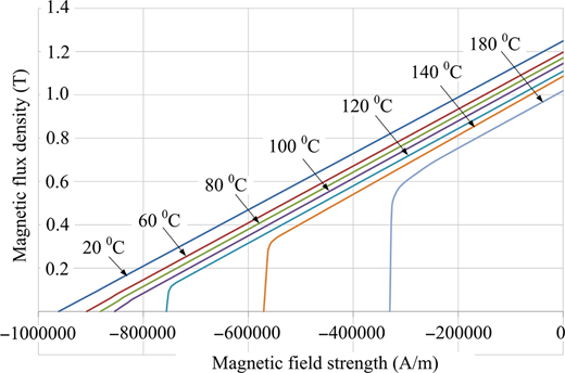
Family of demagnetization characteristics B(H,τs) of magnetically hard N38SH material
Family of demagnetization characteristics B(H,τs) of magnetically hard N38SH material
The authors of the paper curried out simulation and experimental studies aimed at investigating the effect of temperature of the machine’s components on the shape of the e(t) waveform and on the value of the electromotive force in LSPMSMs. Moreover, the temperature dependence of the kE = E1max/n coefficient, where E1max is the amplitude of the fundamental harmonic of the voltage induced in the winding and n is the rotational rotor speed, was calculated. The calculations were carried out using the software developed by the authors for the field two-dimensional (2D) analysis of electromagnetic and thermal phenomena in the permanent magnet synchronous motor adopted to asynchronous starting (Baranski et al., 2017, 2019, 2020). Experimental research was carried out on a specially constructed laboratory stand.
2. Mathematical model of electromagnetic and thermal phenomena of line start permanent magnet synchronous motors
The model developed by the authors, a 2D mathematical model of an LSPMSM has been presented in detail in Baranski et al. (2019, 2020). This model includes equations describing magnetic field distribution, thermal field distribution and mechanical equilibrium. It was assumed that the magnetic properties of the stator and rotor core, as well as permanent magnets, are due to equations H = νB and respectively, B =µ0(H + θm), where B is the vector of magnetic flux density, H is the magnetic field strength vector, θm is the magnetization vector in the region with permanent magnets, ν is the magnetic reluctivity and µ0 is the magnetic permeability of the vacuum. In the developed field model of thermal phenomena, the equation of the magnetic field is associated with the loop equations of the electrical circuits of the device and with the mechanical equilibrium equation of the drive system (Demenko, 1996; Driesen and Hameyer, 2002; Baranski et al., 2019, 2020):
where Ji is the moment of inertia of the movable elements of the system, γ is the angular position of the rotor, TL is the load torque. The driving torque T is determined on the basis of the calculated magnetic field distribution (Demenko, 1996).
In the process of converting electrical energy into a mechanical one, power loss occurs, which is the source of heat in the machine. The temperature increase of the motor’s components causes changes in the electrical, magnetic and thermal properties of materials (Baranski et al., 2019, 2020). The temperature change significantly affects magnetic properties of permanent magnets (McFarland and Jahns, 2012; Baranski et al., 2020). For this reason, the mathematical model of the motor has been fitted with an equation describing thermal phenomena (Baranski et al., 2020):
The heat capacity of the materials is established by the specific mass ρ and the specific heat capacity ch. Q = −k∇τ is the conductive heat flux, where k is the thermal conductivity of the medium and τ is the temperature. Ph is the power-loss density. Convection heat transfer on the solid–fluid boundaries along the air gap is calculated considering the state of the airflow in the air gap (Baranski, 2019). The convection thermal coefficient in the outer surface of the frame was calibrated to match the temperatures measured at the motor frame (Baranski, 2019).
Numerical methods based on discretization of space and time are used to solve non-linear equations of the field model of coupled phenomena in an LSPMSM (Demenko, 1996). The FEM was used to determine magnetic field and temperature field distributions in the analyzed motor (Demenko, 1996; Driesen and Hameyer, 2002). For this purpose, the considered domain has been divided into triangular elements. After the discretization of time and using a backward differential scheme, a system of non-linear algebraic equations describing transient electromagnetic and thermal phenomena in the motor, taking into account the rotor’s motion, was obtained:
where S is the magnetic reluctance matrix, φ is the vector of potentials in nodes of the mesh, i is the vector of loop currents, U is the vector of supply voltages, M is the matrix of coefficients, R and L are the matrices of resistances and inductances of the windings and the supply system circuit, N is the matrix describing the number of turns assigned to the mesh nodes, G is the matrix of equivalent electrical conductances, Sτ is the matrix of thermal conductances, Mτ is the matrix of thermal capacitances, τ is the vector of unknown temperatures, P is the vector of heat sources, Kτb and Kτo are the matrices of the coefficient describing heat transfer transport to the ambience of the motor. In the above relationships, Δt = tn−tn−1 is the length of a time-step, index n denotes the quantities of the actual time-step number t = tn and index n−1 denotes the previous time-step number t = tn−1. For example: Sn = S(tn), φn = φ (tn).
In the developed model of electromagnetic-thermal phenomena, the distorted element method was used to map the rotor position change (Baranski et al., 2017). The effect of temperature on elements of the vector θm matrixes R, G and S (Baranski et al., 2019, 2020) was also taken into account.
The equations of the comprehensive discrete model, (3)–(5), are solved by using the Newton–Raphson procedure coupled with the block-over relaxation method (Baranski, 2019; Baranski et al., 2020). Based on the presented algorithm, software for analyzing the effect of temperature on LSPMSM operations was developed. The software has been developed in the Borland–Delphi environment.
3. Tested motor and laboratory stand
Figure 2 shows the structure of the considered motor. The stator core shape of the mass-produced, general-purpose, 3-phase, 4 pole, 3 kW output power squirrel cage motor of Sg100L-4B type has been used.
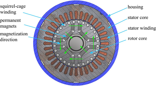
There are 36 drop-shaped slots in the stator and 24 round slots in the rotor. NdFeB magnets of the N38SH type, U-shaped, are placed inside the rotor. The motor is supplied by a 3-phase balanced system of 400 V line to line voltage. The stator winding is made of winding wire with insulation class F and an allowable maximum temperature equal to 155°C. The motor rated parameters have been summarized in Table 1.
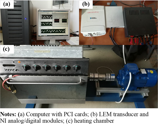
The developed test stand for determining the effect of temperature of magnets on voltage courses e(t) induced in the stator winding is shown in Figure 3.
4. Results and discussions
The software developed by the authors was used to analyze the effect of temperature on the e(t) waveform and BEMF value of the induced voltages in the stator windings. The calculations were carried out assuming that the rotor speed is equal to 1,500 rpm and no current flows in the stator winding. The obtained results of the simulation were compared to the results carried out under the same conditions of laboratory tests. Experimental studies were carried out on the computerized measuring stand developed and built by the authors – Figure 3. The tested LSPMS motor was placed in a heating chamber. The motor was driven by a squirrel-cage induction motor powered by a converter. The tests were carried out for several set temperatures of fixed components of the motor. These temperatures ranged from 26 to 140°C. The measurements were made after the temperature of the motor components was established. The waveforms were registered using measuring equipment of National Instruments Corporation. A detailed description of this apparatus is presented in Baranski (2019). It should be emphasized that the voltage tests were carried out on the motor after installing magnetized magnets in the rotor. Before the measurements of induced voltage, no motor starts were made and no current in the windings of the stator.
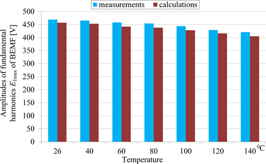
Figure 4 shows eU-V(t) waveforms of line-to-line voltages obtained on the basis of simulations (Figure 4a) and measurements (Figure 4b) for given values of the temperature τs. It was limited to showing only one of the three line-to-line voltages. The waveforms of the other line-to-line voltages have the same shape but are shifted in phase. The comparison of the motor eU-V(t) waveforms obtained on the basis of measurements and calculations is shown in Figure 5. The waveform of the induced voltage is affected by stator and rotor slots. The magnetic flux pulsations caused by the changing position of the stator slots relative to the rotor slots during the rotor’s rotation, result in higher voltage harmonics. The results of the simulation and experimental studies confirm that as the temperature increases, both the magnetic flux generated by the magnets and the induced voltage decreases. It should also be noted that the temperature has little effect on the shape of the voltage waveform. Figure 6 presents higher harmonics for the selected temperatures τs included in the measured and calculated voltages. In addition to the basic harmonic, higher harmonics due to stator and rotor slots are visible. The differences between the amplitudes of individual voltage harmonics determined on the basis of measurements and simulation tests are caused, among others, by the use of a 2D model of phenomena, the assumed density of space and time discretization, as well as the imprecise mapping of real characteristics of soft and hard magnetic materials. The amplitudes of the harmonic eU-V(t) voltages obtained for given τs temperatures are shown in Figure 7. The calculated kE_C and measured kE_M coefficients obtained for given temperatures was summarized in Table 2. The results confirmed that the kE coefficient decreases with the rise of temperature in stator winding.
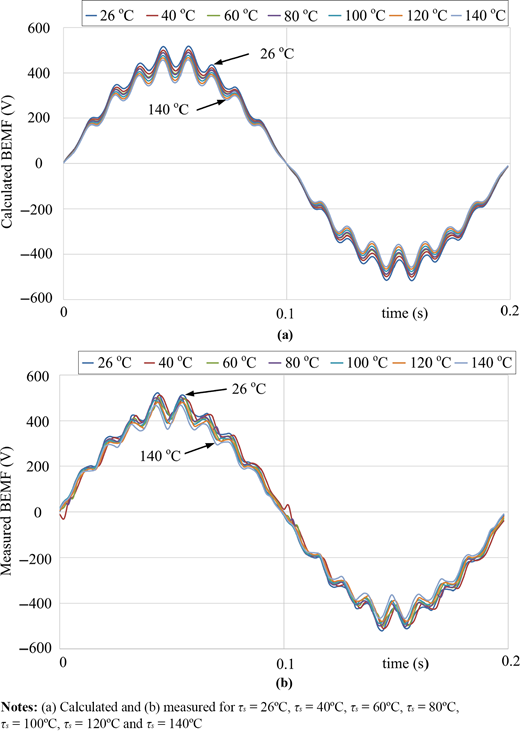
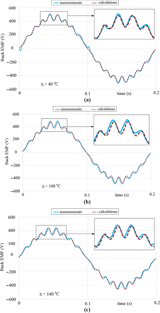
Calculated and measured eU-V(t) waveforms for (a) τs = 40°C, (b) τs = 80°C and (c) τs = 140°C
Calculated and measured eU-V(t) waveforms for (a) τs = 40°C, (b) τs = 80°C and (c) τs = 140°C
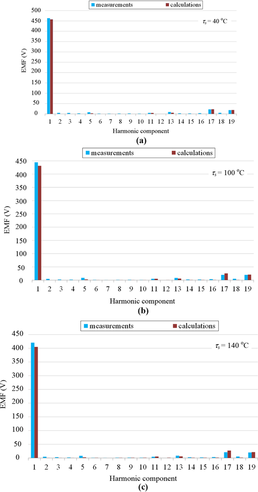
Higher harmonics in calculated and measured eU-V(t) waveforms for (a) τs = 40°C, (b) τs = 80°C and (c) τs = 140°C
Higher harmonics in calculated and measured eU-V(t) waveforms for (a) τs = 40°C, (b) τs = 80°C and (c) τs = 140°C
The BEMF kE_M and kE_C coefficients depend on temperature
| τs [°C] | 26 | 40 | 60 | 80 | 100 | 120 | 140 |
|---|---|---|---|---|---|---|---|
| kE_M [V/rpm] | 0.313 | 0.310 | 0.305 | 0.303 | 0.296 | 0.289 | 0.281 |
| kE_C [V/rpm] | 0.305 | 0.302 | 0.295 | 0.292 | 0.285 | 0.277 | 0.275 |
| τs [°C] | 26 | 40 | 60 | 80 | 100 | 120 | 140 |
|---|---|---|---|---|---|---|---|
| kE_M [V/rpm] | 0.313 | 0.310 | 0.305 | 0.303 | 0.296 | 0.289 | 0.281 |
| kE_C [V/rpm] | 0.305 | 0.302 | 0.295 | 0.292 | 0.285 | 0.277 | 0.275 |
To assess the discrepancy between the results of calculations and measurements (Figure 7), the factor χE% was introduced, determining the relative difference between the harmonics’ amplitudes of the measured and calculated voltages:
where E1maxM and E1maxC are the amplitudes of the harmonic fundamental of the voltages e(t) obtained from measurements and calculations, respectively. The calculated values of χE% for the considered operation conditions have been summarized in Table 3. The table shows that the relative percentage difference between the results of the calculations and measurements does not exceed 3.80%.
Summary of the fundamental harmonic of the BEMF and BEMF coefficient χE%
| τs [°C] | E1maxC [V] | E1maxM [V] | χE% [%] |
|---|---|---|---|
| 26 | 457 | 469 | 2.56 |
| 40 | 453 | 465 | 2.58 |
| 60 | 442 | 458 | 3.49 |
| 80 | 438 | 454 | 3.52 |
| 100 | 428 | 444 | 3.60 |
| 120 | 416 | 429 | 3.03 |
| 140 | 405 | 421 | 3.80 |
| τs [°C] | E1maxC [V] | E1maxM [V] | χE% [%] |
|---|---|---|---|
| 26 | 457 | 469 | 2.56 |
| 40 | 453 | 465 | 2.58 |
| 60 | 442 | 458 | 3.49 |
| 80 | 438 | 454 | 3.52 |
| 100 | 428 | 444 | 3.60 |
| 120 | 416 | 429 | 3.03 |
| 140 | 405 | 421 | 3.80 |
To check whether high temperature permanently affected the voltage induced in the stator windings in the studied temperature range of magnets, the voltage waveforms were measured and compared:
after installing the magnets but before increasing the temperature of the machine; and
during the course of the induced voltages after all tests related to heating the machine were performed.
The measurements of the voltage waveforms e(t) before and after tests related to the heating of the machine were carried out at a temperature of τs = 26oC. It should be emphasized that after mounting the magnets in the machine, only the temperature of the motor components was changed and the magnet flux was not stabilized by the inrush armature. The measurement results are presented in Figure 8.
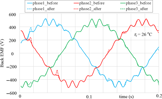
Measured line-to-line e(t) waveforms for τs = 26°C before and after heating processes
Measured line-to-line e(t) waveforms for τs = 26°C before and after heating processes
The measured e(t) waveforms show that the operation of magnets in the studied range of temperature changes from 26oC to 140oC and their repeated cooling to the ambient temperature did little to affect the course and value of the induced voltages. It was found that after all the tests, the effective voltage value determined at 26oC decreased by approx. 0.4% in relation to the condition after the magnets were placed in the rotor.
Visible slight differences in the shape of the e(t) waveforms induced before and after the tests at increased temperature are probably caused by the partial demagnetization of the magnet’s sub-areas lying near the rotor bars (Baranski et al., 2017). This phenomenon is associated with the pulsation of the magnet flux resulting from the grooving of the stator and rotor as well as with the currents induced in the rotor’s rods by changes in this flux. As the temperature increases, the magnet resistance to demagnetization decreases, which adversely affects the process.
Due to the possibility of permanent and significant reduction of the magnet flux resulting in deterioration of the motor’s functional parameters, experimental tests for τs > 140oC were not carried out. The measurement was limited to simulation tests. The induced e(t) waveforms in the LSPMSM with a magnet temperature of 180oC and 200oC, respectively, were analyzed. The induced line-to-line eU-V(t) waveforms were obtained and are presented in Figure 9. For comparison, the figure shows the eU-V(t) waveform obtained at a temperature of 140oC.
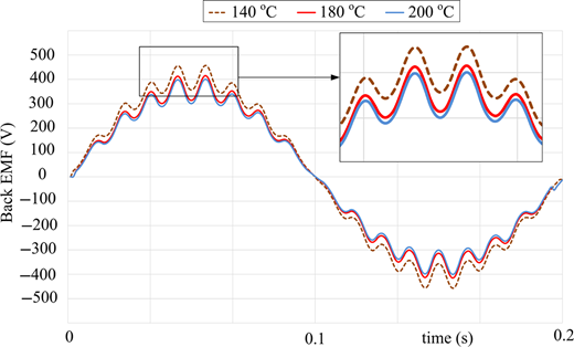
As expected, an additional temperature increase reduces the value of the fundamental amplitude of the harmonic of the electromotive force. The fundamental harmonic values obtained by the calculations are: E1max(180°C) = 368 V and E1max(200°C) = 333 V, respectively. As we can see, the magnetic properties of the permanent magnets have deteriorated significantly. This weakens the magnetic field generated by the magnets in an LSPMSM and reduces the value of both induced voltage and electromagnetic moment. A temperature of 150°C is the permissible operating temperature for N38SH magnets used in the motor.
To determine the relative percentage decrease in the value of the fundamental harmonic amplitude E1max, determined on the basis of calculations, the value of the coefficient ΔαE%, calculated on the basis of formula (7), is summarized in Table 4.
Summary of the coefficient αE%
| τs [°C] | ΔαE% [%] |
|---|---|
| 40 | 0.88 |
| 60 | 3.28 |
| 80 | 4.16 |
| 100 | 6.56 |
| 120 | 9.19 |
| 140 | 11.30 |
| 180 | 19.47 |
| 200 | 27.13 |
| τs [°C] | ΔαE% [%] |
|---|---|
| 40 | 0.88 |
| 60 | 3.28 |
| 80 | 4.16 |
| 100 | 6.56 |
| 120 | 9.19 |
| 140 | 11.30 |
| 180 | 19.47 |
| 200 | 27.13 |
This factor determines the percentage change in E1max that occurs with increasing temperature:
where E1max(26°C) is the value of the fundamental harmonic amplitude of the voltage eU-V(t) for the reference temperature of the motor components reaching 26°C, while E1max(τs) is the value of the fundamental harmonic amplitude of the voltage eU-V(t) for the set temperature τs.
For τs = 200 oC, the relative decrease of E1max, with respect to the amplitude of the fundamental harmonic of the voltage induced in a temperature of 26°C, is approximately 27%.
5. Conclusions
The paper presents an analysis of the effect of temperature on the waveforms of the electromotive force induced in LSPMSM stator windings. The voltage induced in the machine during the generator’s operation and the open circuit of the stator windings was investigated. The developed algorithm and program for analyzing the impact of temperature on the transient electromagnetic, thermal and mechanical phenomena in permanent magnet motors was used to conduct simulation tests. In an attempt to verify the results of the calculations for the induced voltage waveforms, a special laboratory stand has been constructed for this purpose. The tests were carried out for the given temperatures of the motor components. The survey showed good agreement between the calculations and experimental tests. Thus, the reliability and usefulness of the developed software for analyzing the effect of temperature on the behavior of permanent magnet machines were confirmed. It should be emphasized that the obtained results could apply on the magnets type that are used in this research. Due to the different temperature dependence of the magnets, there is a probability that for other types of magnetic materials, the results can vary in magnitude of the measured and calculated electromotive force, but the main conclusions will be the same.
Funding: This research was funded by the Polish Government, grant number (0212/SBAD/0538).
