

The purpose of this paper is to provide an analysis of the performance of a new five-phase doubly fed induction generator (DFIG).
This paper presents the results of a research work related to five-phase DFIG framing, including the development of an analytical model, FEM analysis as well as the results of laboratory tests of the prototype. The proposed behavioral level analytical model is based on the winding function approach. The developed DFIG model was used at the design stage to simulate the generator’s no-load and load state. Then, the results of the FEM analysis were shown and compared with the results of laboratory tests of selected DFIG operating states.
The paper provides the results of analytical and FEM simulation and measurement tests of the new five-phase dual-feed induction generator. The use of the MATLAB Simscape modeling language allows for easy and quick implementation of the model. Design assumptions and analytical model-based analysis have been verified using FEM analysis and measurements performed on the prototype. The results of the presented research validate the design process as well as show the five-phase winding design advantage over the three-phase solution regarding the control winding power quality.
The main disadvantage of the winding function approach-based model development is the simplification regarding omitting the tangential airgap flux density component. However, this fault only applies to large airgap machines and is insignificant in induction machines. The results of the DFIG analyses were limited to the basic operating states of the generator, i.e. the no-load state, the inductive and resistive load.
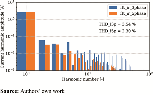
The novel DFIG with five phase rotor control winding can operate as a regular three-phase machine in an electric power generation system and allows for improved control winding power quality of the proposed electrical energy generation system. This increase in power quality is due to the rotor control windings inverter-based PWM supply voltage, which operates with a wider per-phase supply voltage range than a three-phase system. This phenomenon was quantified using control winding current harmonic analysis.
The paper provides the results of analytical and FEM simulation and measurement tests of the new five-phase dual-feed induction generator.
1. Introduction
The doubly fed induction generators (DFIGs) have well-known advantages of simple constructions and low maintenance and are industrially applicable. They are mainly used in modern wind power plants instead of permanent magnet synchronous generators (Han et al., 2018; Kumar and Choudhary, 2015; Morawiec et al., 2020b; Protsenko and Xu, 2007; Sartaj et al., 2019).
Nowadays, when the industry market increases rapidly, semiconductors and converters are getting cheaper, and different and innovative solutions are being explored. Multiphase machines have several advantages over three-phase systems, such as fault tolerance, higher torque density and lower torque pulsation (Maciejewski and Iwański, 2021; Morawiec et al., 2020a).
This paper presents a behavioral level model of a novel five-phase DFIG based on the winding function approach (WFA). The main advantage of this approach is that the model description is based on actual machine winding distribution and the airgap geometry (Krause et al., 2013; Morawiec et al., 2020a; Szypulski and Iwański, 2018). The main disadvantage of WFA is the simplification regarding omitting the tangential airgap flux density component (Krause et al., 2013; Szypulski and Iwański, 2018). However, this fault only applies to large airgap machines and is insignificant in induction machines (Adamowicz et al., 2015; Kołodziejek and Wachowiak, 2022).
The developed model objective is to verify the modeling approach for further model development. The proposed model based on the WFA should be relatively easy to simplify and convert to the arbitrary orthogonal reference frame. The model should also allow for further development and incorporation of selected physical phenomena such as internal machine asymmetry, nonsinusoidal winding distribution and magnetic saturation of the core. The model developed based on WFA and defined using multiphase machine variables meets said criteria.
This effort aims to present a complete research cycle, including the design and modeling stage, prototype manufacturing and the laboratory test of the novel five-phase DFIG in selected operating conditions. The detailed comparison between three-phase and five-phase DFIGs has been described in Ryndzionek et al. (2022). The five-phase DFIG has a significant advantage over existing constructions, an operation with a damaged excitation phase (or even two phases). The aim is that the generator can operate for a longer period without a breakdown, thereby reducing the downtime caused by power electronics failures.
The main contribution of the presented research is to validate the proposed model-based design approach and to verify the improved electrical power quality of the control winding.
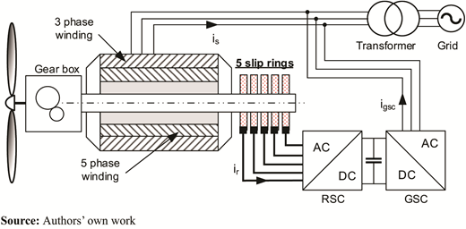
The paper is organized as follows: the structure of the developed five-phase DFIG is introduced (Figure 1), and its principle of operation and mathematical model is described in Section 2. The FEM simulation of the prototype is presented in Section 3. Section 4 explains the manufacturing of the prototypes and experimental analysis. Finally, the paper ends with a summary of the obtained results.
2. Mathematical model of five-phase doubly fed induction generator
The specifications of the prototype DFIGs used in this study are shown in Table 1. This generator has a six-pole, three-phase stator winding with one parallel branch and was constructed in a frame size of 132 mm. The generator has been developed using the original stator from a 5.5 kW Sg132m-6 induction motor. The five-phase rotor control winding and core have been designed from scratch to fit and perform with the original core and winding of the selected induction motor.
Specifications of the prototype DFIG
| Parameter | Value | |
|---|---|---|
| Rated power | Pn | 4 kW |
| Voltage | Un | 400 V |
| Pair poles | P | 3 |
| Stator phases | Ms | 3 |
| Rotor phases | Mr | 5 |
| Stator slots | Qs | 36 |
| Rotor slots | Qr | 30 |
| Airgap length | Lg | 0.3 mm |
| Axial length | Ls | 149 |
| Stator external diameter | Dse | 208 mm |
| Rotor external diameter | Dre | 147 mm |
The rotor was manufactured with a set of five slip rings.
The machine design was based on a predetermined minimum and maximum speed, the set output electric power and the maximum rotor voltage (Ur < Us) corresponding with the operating speed range.
2.1 Basic model of the five-phase doubly fed induction generator
The stator and rotor voltage equations describe the general form of the five-phase DFIG model:
where:
Us, Ur = stator and rotor voltage vectors;
Is, Ir = stator and rotor current vectors;
Rs, Rr = stator and rotor resistance matrix; and
Ψs, Ψr = stator and rotor flux linkage vectors.
The flux linkage equation for the stator and rotor winding is:
where:
Lss, Lrr = inductance matrix of stator and rotor windings; and
Lsr = the matrix of mutual inductances between stator and rotor windings.
The five-phase DFIG model completes the mechanical equation:
where:
tem = electromagnetic torque;
tl = load torque;
J = a moment of the rotor and load inertia;
ω = rotor speed; and
D = damping factor.
The magnetomotive force of the stator winding:
where Ns is the number of stator conductors.
The stator winding distribution is represented by:
The general stator flux density distribution has been represented by:
The detailed stator flux density distribution:
where ias, ibs and ics are stator phase current.
Finally, the flux linkage is described by:
Thus, the stator flux linkage is:
The rotor winding distribution:
And the rotor flux linkage is:
Stator self-inductance a is:
And stator mutual inductances a are also the same:
Self-inductance of ar winding:
Rotor winding mutual inductances concerning the ar phase:
The stator magnetizing inductance is defined as:
The rotor magnetizing inductance is defined as:
where g is the length of the air gap, r is the external radius of the rotor and l is the axial length of the generator.
2.2 Model implementation
The equations of the DFIG mathematical model presented in the previous chapter were used to develop the generator simulation model.
An important issue was selecting an appropriate environment for simulating electromechanical systems. The MATLAB Simscape software was chosen to simulate and analyze selected DFIG operating states. On the one hand, this program has a library with many electromechanical, electrical and electronic components. On the other hand, it offers a physical modeling language for developing custom models.
Simulations in MATLAB Simcape are performed by the idea of physical modeling, in which even a complex system consists of elements (models) representing physical components and their real connections. Using this approach, it is possible to model multidomain systems, where you can integrate components from different physical systems (electrical, mechanical, hydraulic, thermal, etc.).
The DFIG component model was developed as a new component using the Simscape physical modeling language. The model has been defined in a text file whose structure conforms to the language specification. The most important sections of the model include:
declaration, where the types and names of parameters;
branches, in which it contains the relation between variables and terminals, between through and across variables; and
equation, where behavioral model equations are defined.
Selected lines of the developed DFIG component file, representing the main sections of the model, are presented in the following listing.
component DFIG % component name
nodes% as stator nodes
as1 = foundation.electrical.electrical;
as2 = foundation.electrical.electrical;
(…)
end
variables
ias = 0, ‘A’; % as current
vas = 0, ‘V’; % as voltage
fas = 0, ‘Wb’; % as flux linkage
ang = 0, ‘rad’; % rotor angular position
(…)
end
parameters
Lsr = 0.29, ‘H’; % mutual inductance
Rs = 2.5, ‘Ohm’; % stator resistance
(…)
end
branches
ias: as1.i -> as2.i; % stator current
(…)
end
equations
vas == as1.v - as2.v; % stator voltage
(…)
Lasar == Lsr*cos(p*ang); % mutual inductance
(…)
vas == ias*Rs + fas.der; % stator equation
(…)
end
The main advantage of this approach is the possibility of intuitive writing of differential equations without the necessity to analyze the specific requirements of numerical methods.
To define a derivative, in the equation section, the operator “der” should be added to the appropriate variable.
The self and mutual inductances of the generator windings are defined according to the equations presented in Section 2 and can be easily modified to take into account higher harmonics.
The developed DFIG model was used to simulate the generator’s no-load and load state.
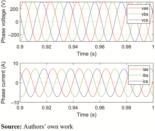
The generator is driven at a constant speed, and the rotor control windings are supplied with alternating currents shifted in phase by 2/5π. The generator load level is controlled by changing the value of the resistance connected to the stator terminals. The amplitude and frequency of the rotor currents and rotor speed are adjusted to the measurement conditions. The parameters of the DFIG model are calculated based on the design data, the no-load test and the short-circuit test (Table 2).
Five-phase DFIG model parameters
| Parameter | |
|---|---|
| Stator resistance, Rs | 2.5 Ω |
| Rotor resistance, Rr | 2.2 Ω |
| Stator-rotor mutual inductance, Lsr | 0.29 H |
| Stator winding leakage inductance, Lls | 15 mH |
| Rotor winding leakage inductance, Llr | 15 mH |
| Motor damping constant, Bm | 5.3 × 10⁻³m2 kg/s |
| Rotor inertia, Jw | 0.028 kg |
| Number of pair poles, p | 3 |
| Stator to rotor turn ratio, Ns/Nr | 2.2 |
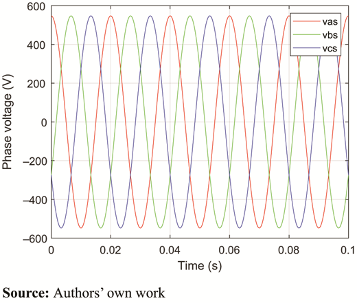
In the no-load state (Figure 2), the flux in the machine is excited by the flow of rotor currents. The no-load voltage amplitude (Us0m) induced in stator winding is defined by:
where:
Lsr = amplitude of the mutual inductance between stator and rotor windings;
Irm = amplitude of rotor current;
fr = frequency of rotor current; and
ωrm = angular velocity of the rotor.
Two components can be distinguished in the induced voltage of the stator. Transformation-induced voltage is related to the frequency of rotor current changes and rotation-induced voltage resulting from the rotation of the excitation field.
Moreover, the load simulation has been developed. The result of the simulation has been presented in Figure 3.
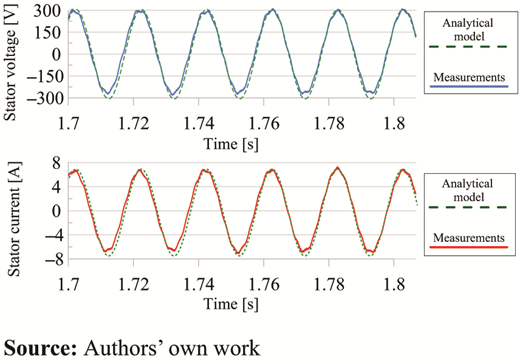
Finally, the analytical calculation from the model has been compared with the measurement results (Figure 4). The model shows very high convergence, and the other measurement results will be presented in Section 4.
3. The FEA analysis of five-phase doubly fed induction generator
The five-phase DFIG has been designed using the 3D CAD software also. The simulations were conducted to verify the analytical design calculated dimensions and parameters. The Ansys Maxwell and RMxprt design have been used. Moreover, FEA validated the designed prototype’s capability to perform in different operating conditions.
The complete model is used to build the model, and its total number of mesh elements is roughly 12,000. The results are almost the same as the model with 20,000 elements. The time step in the transient simulation was 0.2 ms, and the recorded field distribution was at 2 ms. During the FEM analysis, the rotor control winding was excited by five-phase voltage source using an external circuit model. The simulations have been performed for the generator operation in off-grid conditions with a resistive load connected to the stator terminals. Both the on-load and no-load tests have been conducted.
Figure 5 shows the 2D and 3D FEM simulations of DFIG’s flux density distribution. The maximum value of flux density is 1.4 T, and the results of both simulations are similar. However, the 3D simulations better represent the phenomenon of slot harmonics.
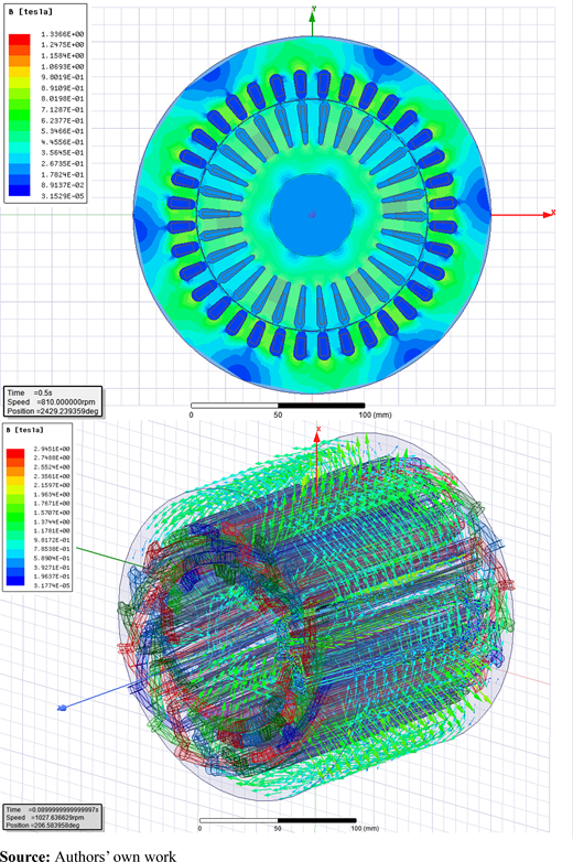
FEA 2D and 3D simulation of the stator and rotor core flux density distribution
FEA 2D and 3D simulation of the stator and rotor core flux density distribution
The maximum value of flux density in the air gap is 0.75 T (Figure 6). The results fit in desired ranges. Moreover, the flux distribution corresponds to the stator and rotor slots distribution.
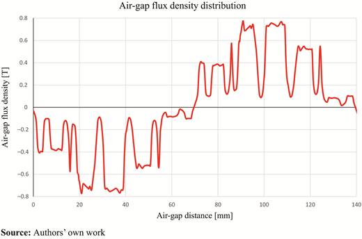
The simulation results will be compared in Section 4.
4. Laboratory tests
This paper uses measurements to analyze and validate the performance benefits of the proposed five-phase DFIG and verify the developed prototype construction (Figure 7). The primary purpose of the laboratory test was to verify the five-phase DFIG operation at different electric load and rotational velocity conditions.
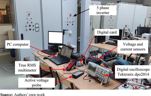
The measurement was performed at a constant speed of 810 rpm without any load. The DFIG stator is star-connected, and the measurements have been made for different rotor currents.
Those measurements have been compared with simulation results.
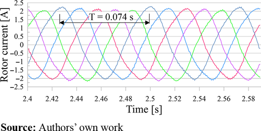
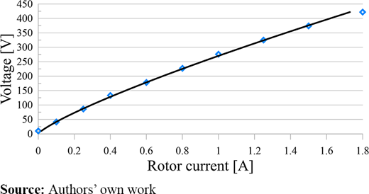
Figure 8 shows experimental test results. The rotor current exciting the machine is raised several times over the measurement period. These results have been compared with the FEA simulations (with the third and fourth/final steps in the rotor current rising sequence). Moreover, the open circuit characteristics of the rotor currents (Figure 9) and stator voltage (Figure 10) have been presented.
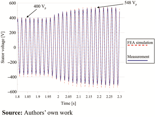
Induced voltage measurement and simulation under the rotor current exciter (Ir RMS = 1.0 A and 1.5 A)
Induced voltage measurement and simulation under the rotor current exciter (Ir RMS = 1.0 A and 1.5 A)
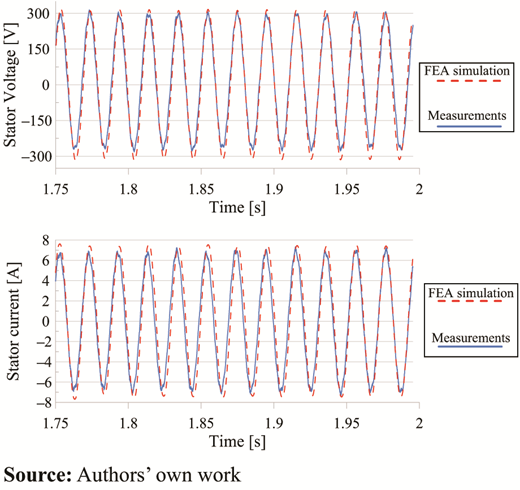
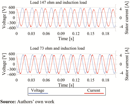
The measurements and FEA simulation results are shown in Figures 11 and 12. The waveforms show good convergence between simulations and measurements, around 10–15 V. The second measurement has been performed with different load conditions (resistive and inductive). In Figure 12, the mixed load has been performed. The active and reactive power was approximately 2 kW and 0.5 kVar.
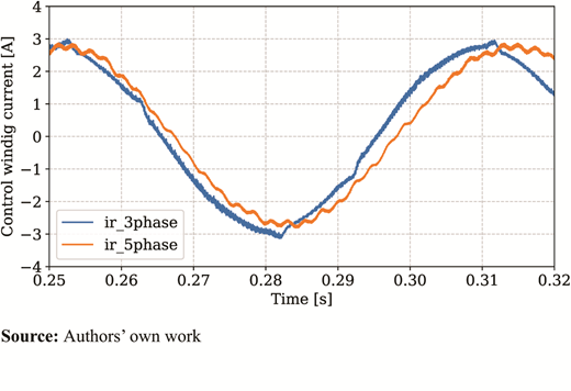
One of the main design advantages of the multiphase control winding is more flexible frequency converter control, where more advanced PWM control strategies can be implemented (Szczepankowski et al., 2021). The main advantage is the improvement in the rotor control winding supply current quality. Figures 13 and 14 show the control winding supply current in three- and five-phase rotor winding and the amplitude spectrum of those currents. The overall THD coefficient for the five-phase control winding is lower than for the three-phase one, demonstrating the higher quality of the supply rotor current.
5. Conclusions
This paper proposes a novel five-phase DFIG dedicated to modern wind power plants. The proposed generator has been developed, and a prototype machine has been manufactured and tested under different operating conditions. Design assumptions and analytical model-based calculations have been verified using FEM analysis and measurements performed on the prototype. The DFIG with five-phase rotor can operate as a regular three-phase machine in an electric power generation system. Further investigation into the machine’s performance will focus on coping with output power quality during single or even dual rotor phase control winding failures due to the inverter or the slip ring assembly fault. However, even with the standard motor stator, the machine could supply the load with both active and reactive power.
The authors would like to thank the MESCO, an authorized distributor of ANSYS, for granting the Ansys Electronics Desktop license. This work was supported by the Gdańsk University of Technology and IDUB Program under Grant 122020IDUBI.3.3.

