

1-20 of 34251
Keywords: ORB feature point extraction
Close
Follow your search
Access your saved searches in your account
Would you like to receive an alert when new items match your search?
Journal

Publishes high quality research on the latest developments relating to the use of robotic technology.
Journal Articles
Industrial Robot 1–12.
Published: 14 September 2026
in Image-based visual servoing and graph matching: a strategy for high-precision robotic assembly
> Industrial Robot: the international journal of robotics research and application
Published: 14 September 2026
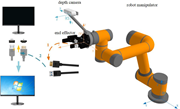
Figure 1 System configuration of the assembly strategy Source: Authors’ own work A system diagram shows a robot manipulator with a depth camera, end effector, coordinate frames, display, and cable connections. The robot manipulator carries an end effector and a depth camera. Coordinate fram... More about this image found in System configuration of the assembly strategy Source: Authors’ own work ...
in Image-based visual servoing and graph matching: a strategy for high-precision robotic assembly
> Industrial Robot: the international journal of robotics research and application
Published: 14 September 2026
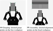
Figure 2 Desired feature points (green crosses) for the control strategy Source: Authors’ own work Two panels show desired grasp points on a free workpiece and desired alignment points on a fixed workpiece. The panel a view marks 4 desired grasp points with plus symbols at the corners of th... More about this image found in Desired feature points (green crosses) for the control strategy Source: ...
in Image-based visual servoing and graph matching: a strategy for high-precision robotic assembly
> Industrial Robot: the international journal of robotics research and application
Published: 14 September 2026
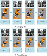
Figure 3 The steps to perform the assembly process Source: Authors’ own work Two flow diagrams show robotic grasping and assembly sequences progressing through approach, alignment, manipulation, and completion. The panel a grasping sequence progresses from approach to align, then grab, and ... More about this image found in The steps to perform the assembly process Source: Authors’ own work T...
in Image-based visual servoing and graph matching: a strategy for high-precision robotic assembly
> Industrial Robot: the international journal of robotics research and application
Published: 14 September 2026
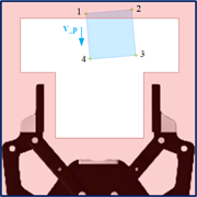
Figure 4 Edge region (red areas) near the image boundaries. A preventive velocity v p is applied to keep feature points from leaving the field of view Source: Authors’ own work A schematic depicts a four-point workpiece region above a gripper, with a V P vector indicating downwa... More about this image found in Edge region (red areas) near the image boundaries. A preventive velocity ...
in Image-based visual servoing and graph matching: a strategy for high-precision robotic assembly
> Industrial Robot: the international journal of robotics research and application
Published: 14 September 2026
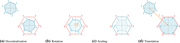
Figure 5 Schematic illustration of the graph matching algorithm Source: Authors’ own work Four schematics show decentralisation, rotation, scaling, and translation applied to numbered six-sided polygons. The panel a decentralisation schematic compares a six-sided polygon with vertices 1 thr... More about this image found in Schematic illustration of the graph matching algorithm Source: Authors’ ...
in Image-based visual servoing and graph matching: a strategy for high-precision robotic assembly
> Industrial Robot: the international journal of robotics research and application
Published: 14 September 2026
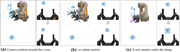
Figure 6 Mapping of 2D image transformations to 3D end-effector poses Source: Authors’ own work Three panels show camera rotation, x y plane translation, and z axis translation with their effects on a viewed marker. The panel a robot view marks rotation negative R around the z axis, while p... More about this image found in Mapping of 2D image transformations to 3D end-effector poses Source: Aut...
in Image-based visual servoing and graph matching: a strategy for high-precision robotic assembly
> Industrial Robot: the international journal of robotics research and application
Published: 14 September 2026
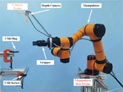
Figure 7 Experimental setup Source: Authors’ own work A robotic assembly setup includes a manipulator, gripper, depth camera, U S B connection, and coordinate frames. The manipulator carries a gripper and a depth camera mounted near the end effector. The camera frame defines x, y, and z axe... More about this image found in Experimental setup Source: Authors’ own work A robotic assembly setup...
in Image-based visual servoing and graph matching: a strategy for high-precision robotic assembly
> Industrial Robot: the international journal of robotics research and application
Published: 14 September 2026
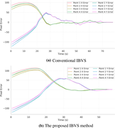
Figure 8 Convergence behavior of feature point errors Source: Authors’ own work Two line graphs compare feature point error convergence for conventional and proposed I B V S methods. The panel a graph plots pixel error against time from 0 to about 78 seconds for x and y errors at points 1 t... More about this image found in Convergence behavior of feature point errors Source: Authors’ own work ...
in Image-based visual servoing and graph matching: a strategy for high-precision robotic assembly
> Industrial Robot: the international journal of robotics research and application
Published: 14 September 2026
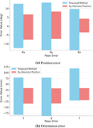
Figure 9 Tolerance to initial pose errors during the grasping stage for the two methods Source: Authors’ own work Two bar charts compare rotational and translational pose error ranges for the proposed method and absolute positioning. The panel a chart compares R x, R y, and R z pose errors ... More about this image found in Tolerance to initial pose errors during the grasping stage for the two meth...
in Image-based visual servoing and graph matching: a strategy for high-precision robotic assembly
> Industrial Robot: the international journal of robotics research and application
Published: 14 September 2026
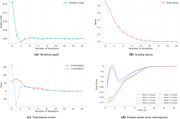
Figure 10 Results of the graph matching algorithm and feature error convergence Source: Authors’ own work Four line graphs show convergence of rotation angle, scaling factor, translation vector, and feature point errors. The panel a graph plots rotation angle in radians against number of it... More about this image found in Results of the graph matching algorithm and feature error convergence Sou...
in Image-based visual servoing and graph matching: a strategy for high-precision robotic assembly
> Industrial Robot: the international journal of robotics research and application
Published: 14 September 2026
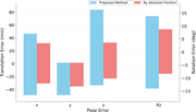
Figure 11 Tolerance to initial pose errors during the assembly stage for the two methods Source: Authors’ own work A bar chart compares pose error ranges for the proposed method and absolute positioning across x, y, z, and R z. The horizontal axis lists x, y, z, and R z pose errors. Transla... More about this image found in Tolerance to initial pose errors during the assembly stage for the two meth...
Journal Articles
Industrial Robot 1–15.
Published: 10 September 2026
in Dynamical system-based adaptive compliant control for mobile manipulators with physical human-robot interaction
> Industrial Robot: the international journal of robotics research and application
Published: 10 September 2026
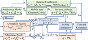
Figure 1 Block diagram of the framework Source: Authors’ own work A control flow diagram links human force input, admittance and kinematic models, arbitration factors, inverse Jacobians, a dynamical system, and a mobile manipulator. Human force F e enters two admittance models and the arbit... More about this image found in Block diagram of the framework Source: Authors’ own work A control fl...
in Dynamical system-based adaptive compliant control for mobile manipulators with physical human-robot interaction
> Industrial Robot: the international journal of robotics research and application
Published: 10 September 2026
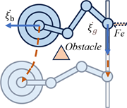
Figure 2 Motion adaptation of the mobile base. ξ ˙ b and ξ ˙ g are the velocities of the mobile base and the gripper, respectively; F e is the external force applied by the human partner Source: Authors’ own work A mobile manipulator moves between... More about this image found in Motion adaptation of the mobile base. ξ ˙ b and ξ ˙...
in Dynamical system-based adaptive compliant control for mobile manipulators with physical human-robot interaction
> Industrial Robot: the international journal of robotics research and application
Published: 10 September 2026
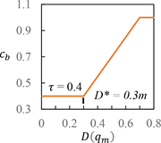
Figure 3 A sample of the damping coefficient c b relative to the distance D ( q m ) Source: Authors’ own work A line plot presents C b against D of q m, with a constant region, a linear increase, and a final plateau. The x-axis gives D of q m from 0 to 0.8. The ... More about this image found in A sample of the damping coefficient c b relative to the distan...
in Dynamical system-based adaptive compliant control for mobile manipulators with physical human-robot interaction
> Industrial Robot: the international journal of robotics research and application
Published: 10 September 2026
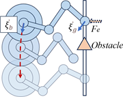
Figure 4 Motion adaptation of the gripper. ξ ˙ b and ξ ˙ g are the velocities of the mobile base and the gripper, respectively; F e is the external force applied by the human partner Source: Authors’ own work A mobile manipulator moves through thr... More about this image found in Motion adaptation of the gripper. ξ ˙ b and ξ ˙ ...
in Dynamical system-based adaptive compliant control for mobile manipulators with physical human-robot interaction
> Industrial Robot: the international journal of robotics research and application
Published: 10 September 2026
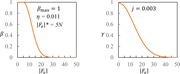
Figure 5 A sample of the factors controlled by the external force Source: Authors’ own work Two plots show beta and gamma decreasing as the magnitude of F e increases from 0 to 50. The left plot gives beta on the y axis from 0 to 1 and the magnitude of F e on the x axis from 0 to 50. Beta r... More about this image found in A sample of the factors controlled by the external force Source: Authors...
in Dynamical system-based adaptive compliant control for mobile manipulators with physical human-robot interaction
> Industrial Robot: the international journal of robotics research and application
Published: 10 September 2026
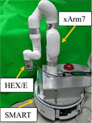
Figure 6 Experimental platform Source: Authors’ own work A robotic arm labelled x Arm 7 is mounted on a S M A R T mobile base, with a H E X slash E sensor at the end effector. The x Arm 7 robotic arm is mounted on top of the S M A R T mobile base. The arm has multiple articulated joints and... More about this image found in Experimental platform Source: Authors’ own work A robotic arm labelle...

