1100016 New deepwater quay unlocks future for UK's premier fish port
By Peter Martin and Roy Glenton (November 2011)
Contribution by Nick Davies
Martin and Glenton (2011) are to be congratulated on both a well-presented paper and a well-considered solution. I am interested to know, however, why structural steel was chosen for the down-stand beam. Elsewhere, good consideration was given to maintenance and corrosion protection. However, the complex open structure of the rear of the beam could not have been easy to paint to the high standard needed. Indeed, future inspection and maintenance painting of the beam will not be simple. Was a concrete solution, perhaps using a combination of precast elements with an in situ core, considered? This could have had cleaner lines and, properly constructed, provided a longer maintenance-free life and simple inspection routines.
Authors' reply
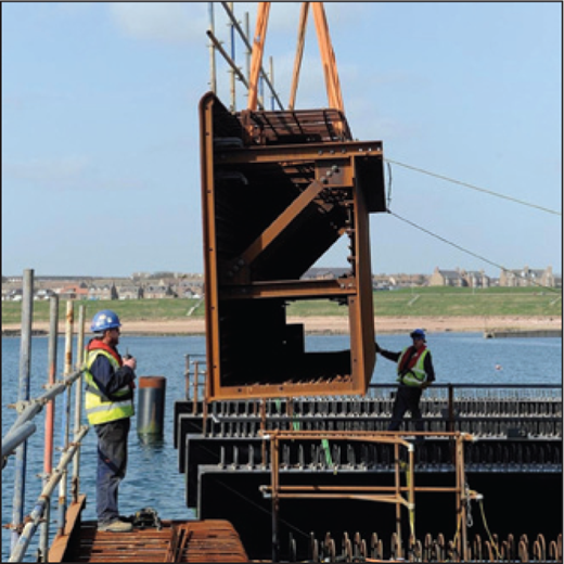
The front down-stand beam is a concrete-filled steel U beam. It is unpainted as it is designed for occasional impact from small vessels nosing into it between the cone fenders and it was felt that painting would not be worthwhile. Both the front and rear vertical plates are flush with the bottom plate at the corners with no outstands and it is expected that corrosion of the steel, which has been allowed for with a sacrificial thickness, will be relatively uniform over the surface of the plates.
Using a steel beam greatly facilitated erection of the main box girders as each segment of the down-stand effectively stabilised the pair of girders to which the segment was connected, allowing very rapid erection of the steel framework. The beam was supplied with internal bracing to hold the shape, and to stabilise the vertical web plates when placing the concrete infill.
For the permanent condition, the beam was designed as a composite member with shear connectors on the inside of the webs providing for full composite action and the concrete infill is integral with the deck concrete. It plays an important role in the structural action of the deck system as its considerable vertical stiffness distributes local patch loading from heavy-lift cranes over a number of main beams and it has a high horizontal resistance for vessel impact.1
We believe that the benefits of the concrete-filled steel down-stand beam, both for erection and service conditions, would have been difficult to obtain from precast or in situ concrete construction.
REFERENCE
1100021 Embodied carbon dioxide as a design tool – a case study
By David Knight and Bill Addis (November 2011)
Contribution by Adrian Campbell
I welcome the addition by Knight and Addis (2011) to the debate on embodied energy and its importance to the development of more sustainable building design. There is an increasing trend towards broader scopings of carbon dioxide, with embodied impacts being one step along that pathway. The key issue for the engineering profession is to what extent does it wish to engage in that trend and use it as part of its normal judgements of overall what is best to build. I would be worried, therefore, if the profession did follow the authors' recommendation to hand the topic over to quantity surveyors. My experience is that engineers are actually better placed to deal with the issues of material selection between options, specification issues within materials and the influence on overall building system design, which all require a greater familiarity with the issues behind the data. The increasing use of analysis tools that model extensive parts of structure and building information modelling (BIM), makes many elements of initial quantity estimation a part of the general design process anyway. Rather than generate another consulting specialism for clients to pay for, we should be making carbon dioxide assessment an inherent part of the overall design method of the engineer, with simple tools to allow early analysis and judgement. This is where the difference is really made.2
Authors' reply
We agree with the contributor's desire to use embodied energy calculations as part of the engineering design process. As he points out, the increasing use of BIM and other tools to determine quantities of materials makes this easier to achieve. However, it is unusual for current BIM models to include materials other than steel and concrete and so they would miss out aspects of the total embodied carbon dioxide. We note that the process of gathering the data required for embodied energy calculation is very similar to the process for quantifying materials for a cost report, and suggest that for simplicity the two are progressed in parallel, with decisions based on the outcomes made by the engineering design team. As tools and BIM models progress, we would expect this process (and simple cost estimation) to be further integrated into the design process.
we should be making carbon dioxide assessment an inherent part of the overall design method of the engineer
REFERENCE
1000058 Tricky truss: design and construction of bridge GE19, London
By David Collings and Lucio Chiodi (November 2011)
Contribution by Frank Marples
The paper by Collings and Chiodi (2011) correctly recognises the need for a specialist designer with experience of major launched truss bridges and this requirement can be applied to all launched bridges. The paper covers many aspects of the design but leaves several key areas requiring clarification. The report by Department of Transport's rail accident investigation branch (RAIB, 2009) raised four causal and ten contributory factors to the failure, not just two. Three of the four causal factors and eight contributory factors could have been addressed by the designer, either by sequence drawings or by an outline methodology, and it is thought that discussion of these factors would have been more informative.
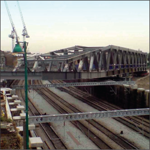
Propulsion was provided by strand jacks but how were these synchronised with the self-propelled modular transport units, which provide further motive force? Permanent articulation for the bridge is addressed but the designer appears not to have specified the bearing restraints during the re-positioning and jack-down stages. These events should have been addressed as required by the CDM Regulations (designer's responsibilities; HMG, 2007) and they are identified as key issues by RAIB. This final point and the RAIB's other causal and contributory factors have been addressed by Marples (2012).
Authors' reply
The contributor notes that a specialist designer should be used for launched bridges, but we would go further and say that a competent designer must be used on all forms of bridges. We would note that personnel in major consultants and contractors change, and clients should ensure that the curricula vitae of staff carrying out the design (and construction) are relevant, rather than rely on brochures and marketing literature.
The contributor outlines comments in the RIAB report on the incident, but it is worth quoting the report to get things in context. The key finding was, ‘the immediate cause of the incident was concrete planks falling from the partly completed deck … triggered by a sudden movement of the deck.’ The key causal factor for the planks falling was, ‘the decision to substitute the positive tie between individual precast concrete permanent formwork planks with cement mortar’ – hence our comment on risk assessments and the perceptions of risk.
On the project the risk was not identified formally by the client's designer, the risk was identified and mitigated by the specialist designer in its risk assessment. However, the risk was reviewed and different perceptions of risk and mitigation given by the temporary works designer.3
The key causal factor for the sudden movement was failure of the temporary bearing system due to, ‘a)… lack of design input to the deck repositioning activity … b) unauthorised modification of the temporary supports by introducing an additional sliding surface … c) installation of lubricated PTFE faced slipper pads on a gradient’. The introduction of an additional sliding plane was clearly an issue of site management, exacerbated by the lack of detailed drawings of the temporary bearing layout. That an item of design can be missed out when there was a series of designers, checkers and consultants whose sole remit was railway safety, makes the authors wonder if such projects have become too bureaucratic and merely a tick-box exercise. We note that the correspondent has a paper outlining improved management controls and we look forward to reading this.
The correspondent had a question on the use of the self-propelled modular transport unit. The bridge was originally intended to be pulled by strands from the east abutment with the rear of the bridge supported on a series of trestles, without the use of a transport unit. The introduction of the unit to the rear meant that the trestles could be omitted, with the unit simply being a movable trestle; no motive force to the truss was provided by the transport unit.
REFERENCES
1100004 Understanding the behaviour of energy geo-structures
By Lyesse Laloui and Alice Di Donna (November 2011)
Contribution by John Parker
Laloui and Di Donna (2011) state in Figure 7 and the accompanying text that the test pile's factor of safety decreased to 0·7 on being heated by 14oC. This was partly because expansion increased load at the top of the pile from 700 kN to 1700 kN. Was this because the test pile was the only pile in the structure that was heated, and load was being transferred from other piles? If all piles were heated, loads applied to the top would not change greatly because the building weight would remain constant. Would this cause the 14oC curve to reduce by 1000 kN throughout, leading to a (more acceptable) factor of safety of approximately 2?4
Authors' reply
The case considered in Figure 7 is an in situ pile test run at the Ecole Polytechnique Fédérale de Lausanne (Laloui et al., 2003). In the experimental set-up only the test pile was subject to thermal loading, while the other piles around it were not equipped as energy piles. In the particular case of a single heated pile, the thermal dilation of the pile is more constrained at the head by the slab due to the fact that the other piles do not dilate. This leads to the strong increase of the load at the head of the pile and consequently to the important reduction of the safety factor.
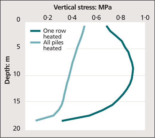
Figure 1 from a forthcoming paper by Kazangba, Dupray and Laloui, provisionally titled ‘Numerical study of a seasonal thermo-piles energy storage’, compares the stresses induced in a pile when only the row of piles to which it belongs is heated with the case where the whole group of piles is heated. Considering that the stress induced in this simulation in the same pile by the mechanical load, averaged on its length, is about 3 MPa, the thermal stress is about 15% of the mechanical load when all piles are heated and about 30% of the mechanical load when only one row of piles is heated. One could therefore conclude that when a group of piles is heated the safety factor will be less affected compared to the case of one isolated energy pile. However, in the case where all the piles are heated together, the slab constraint is still present, even if less strongly. Consequently, the reduction of the safety factor is a realistic problem which has to be considered in design practice.
The pile mentioned in Figure 7 of our paper is an extreme case which aims to underline the phenomena happening in the energy piles when subjected to a thermo-mechanical loading. Moreover, it has to be said that if one considers the other extreme case in which the pile is completely free to move, the state of stress will not be influenced by temperature, but the thermal displacements will be more important and could threaten the performance of the building above during its normal working life. In this second case, the safety factor at the ultimate limit state will not change, but the effects of temperature will become more relevant at the serviceability limit state.
In conclusion, the optimised solution is probably a compromise between the two extreme cases discussed, which should ensure both admissible displacements for the structure and stresses for the piles.