


1100037 A tale of two tunnels-delivering the New Tyne Crossing
By Paul Fenwick, Cliff Jessett, David Dingwall and Malcolm Shaw (February 2012)
Contribution by Bill Tubb
This paper (Fenwick et al., 2012) is excellent and interesting but it failed to mention or give credit to the designer of the structures and perhaps other firms providing their expertise to the success of this project. With regard to the planning, feasibility and finance, complete acknowledgements are given to some 16 firms and authorities, but with respect to the detailed design and construction, only two firms are mentioned.
I used to work for High Point Rendel and I understood it was appointed as lead consultant for the design of the civil works. Is it not reasonable for the design civil engineer involved in a project of this magnitude to have its name listed in the acknowledgements?
Authors' reply
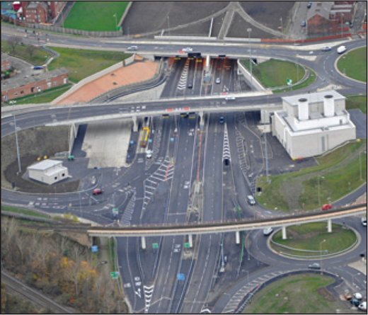
The paper was submitted on behalf of the client body and aimed to cover the whole project from early inception through to completion – some 20 years. As far as acknowledgements were concerned, it was a priority for the client body to acknowledge those firms which have given direct continuous service to Tyne and Wear Integrated Transport Authority throughout that period but obviously acknowledge and give due praise to the concessionaire, TT2 Ltd, and the design-and-build contractor, Bouygues Travaux Public.
While we appreciate the contributor's point, the design-and-build contractor used well over 100 subcontractors (including design consultants) on this project and, no doubt, all would wish to have been acknowledged. To have done so, even for a selection of them, would have been disproportionately detrimental to the main body of the paper because of the word limit set by the editorial panel.
The paper was not about detailed design or, indeed, detailed construction techniques. We would very much like to see these aspects being written up and published by those best placed to do so. Consequently, we have encouraged, and indeed continue to do so, the design-and-build contractor's team to write appropriate papers for the ICE journals, covering the project's many and varied aspects of technical interest.
REFERENCE
1000058 Tricky truss: design and construction of bridge GE19, London
By David Collings and Lucio Chiodi (November 2011)
Contribution by F. Richardson
As a specialist in the Construction (Design and Management) (CDM) Regulations (HMG, 2007), primarily as a CDM co-ordinator, I am interested in the accident and the influence of CDM. I work for URS (Scott Wilson), but was not involved in this project.
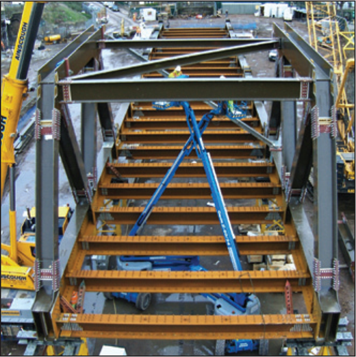
I am surprised there was not more mention of CDM by the authors (Collings and Chiodi, 2011) or in the Rail Accident Investigation Branch's otherwise excellent report (RAIB, 2009), which describes clearly what happened and why – many of the 17 factors the branch identifies potentially point to underlying management issues. The role of CDM coordinator (formerly planning supervisor) is pivotal, yet the authors do not mention this duty holder; furthermore, the report does not explicitly mention CDM at all. The role of coordinator / planning supervisor includes
advising the client on its health and safety management arrangements
working with designers to ensure health and safety gets fair consideration.
The latter point encompasses all permanent and temporary works designers, regardless of who employs them. This was clearly a challenge on the GE19 project, with designers spread through the supply chain (although this is not unusual).
The authors rightly express concern about the multitude of risk assessment scorings, although this is not uncommon. Risk assessment methodology has been a CDM issue for many years. The UK Health and Safety Executive discourages designers from applying numbers, as it can misdirect their focus. Numbers are useful in allowing risks to be prioritised and manipulated in a spreadsheet; however, any scoring system can obscure very low frequency / very high impact risks like those here.
For a major transportation project I recently worked on, the client required us to run a CDM risk register and to use its scoring system. We had to hold regular CDM workshops where designers could discuss risks associated with constructability and agree priorities. I successfully applied this on another transportation project, on a design-and-build basis, and we were able to involve the contractors at the CDM workshops. In both cases, the client-driven, positive health and safety culture worked well.
I would be interested in the authors' experience of working with the planning supervisor on this project and, indeed, the views of the duty holder.
Authors' reply
The contributor outlines his views on the role of the planning supervisor; the authors would not disagree with the comments, but would highlight the need for the planning supervisor to be aware of programme and project management issues in the same way as other disciplines are. They should ensure that all CDM documents are disseminated to all in time to be useful. In addition, we purposefully highlighted that CDM advisors should address the variability in risk assessment methods on an individual project.
The method used by the authors for risk assessment is a standard method and outlined by Collings (2010). The Health and Safety Executive's discouragement of applying numbers to risk assessments is noted, this may be fine for small projects but is at odds with current standards such as Eurocodes (BSI, 2006), which require a more probabilistic approach to risk assessment. On the GE19 project, it was not that the risk was not foreseen but that the mitigation was not adequate.
On the GE19 project, it was not that the risk was not foreseen but that the mitigation was not adequate
REFERENCE
1100004 Understanding the behaviour of energy geo-structures
By Lyesse Laloui and Alice Di Donna (November 2011)
Contribution by Peter Bourne-Webb, Kenichi Soga and Tony Amis
We would like to clarify some statements made by the authors (Laloui and Di Donna, 2011) which may lead to misunderstanding within the broader profession and those outside approaching the possible use of energy geo-structures, and in particular energy piles, for the first time. In particular, such misunderstanding may occur around the authors' presentation and discussion of Figure 7, taken from test 2 of the series undertaken at the Swiss Federal Institute of Technology in Lausanne (EPFL).
Here, it is apparent from the observations that the effect of heating in terms of structural stresses is such that internal stresses within the pile increase. However, as a means of illustrating possible issues concerning the integrity of the pile (and it is not always clear whether geotechnical or structural capacity is being discussed), the authors then assert that had the pile been designed for the external load present at this stage (600 kN; about half the actual design load), based on a factor of safety of 3, then the internal forces mobilised by the imposed temperature change would lead to a significantly decreased factor of safety, ‘seriously threatening the structural integrity (of the pile)’. The contributors find this confusing and believe that it may lead to significant misunderstanding for readers.
The observational data in Figure 7 are for a 25·8 m long pile with a nominal diameter of 0·9 m which, based on details in the lead author's earlier papers, has a geotechnical capacity of about 11 000 kN, and a structural capacity of about 15 000 kN (assuming a concrete 28 day compressive strength of 25 MPa). Thus, based on the load profile in Figure 7, in no way should it be construed that the pile in question failed either structurally or geotechnically. It is unlikely that the authors intended this to be implied but the introduction of a fictitious pile capacity of 1800 kN in the paper could lead to this misunderstanding.
It should be noted that the maximum forces induced in the pile were no more than about 22% of the assumed ultimate structural capacity of 15 000 kN. In terms of global type factors associated with structural integrity (pre-Eurocode), in the UK at least, it was more usual to limit pile shaft working stresses to 0·25 of compressive strength (factor of safety of 4; Eurocode provisions reduce this to about 3 – that is, 0·3 compressive strength). Thus, in reality, based on UK rules, while the thermal load increased the internal forces, the pile in question would need no additional protective measures such as higher concrete strength or larger section size.
Examining the authors' paper from another perspective, if the pile had been designed for an ultimate load of 1800 kN as postulated (again, assuming compressive strength is 25 MPa and geotechnical design properties as previously published), then a 25·8 m pile of 0·32 m diameter would be required, not 0·9 m. If this 0·32 m diameter pile was perfectly restrained against thermal expansion then a temperature change of 14·1°C would result in an additional thermal load of up to about 360 kN, not the 1900 kN actually observed in the larger diameter pile. Thus, while the factor of safety with respect to structural capacity would be reduced (from 3·0 to about 1·9), the outcome is unlikely to be as dramatic as presented by the paper (i.e. factor of safety less than 1) and the apparent over-stress could, if needed, be mitigated with, for example, higher strength concrete.
Thus, for the situation being illustrated in the paper, it is clear two situations (i.e. actual observations from one set of conditions, set against a fictitious capacity) are being combined in an inconsistent manner. While the issue with respect to structural integrity may indeed be valid in some instances, this exposition is rather unhelpful in clarifying this and is likely to lead to unintended angst amongst readers of the paper.
It is considered that the problem of thermal loading is analogous to that of down-drag or heave on piles (Bourne-Webb et al., 2012). Thermally induced geotechnical bearing capacity is unlikely to be a consideration but serviceability may be an issue, as may structural forces within the pile. Thus, it is of great importance that robust methods for estimating these effects are developed and verified for use by the wider engineering profession, and here the ongoing work at EPFL is to be encouraged.
Based on the current state of knowledge, we are largely satisfied that piles will remain unaffected by the heating and cooling effects from a ground-source heat-pump system provided that when designing and using energy piles the following guidelines are followed.
Early coordination between geotechnical, structural and services engineer and ground-loop design team to agree foundation details, installation technique and levels of system redundancy (factor of safety on energy supply) required.
Ground-loop designer to ensure heat extraction should equal ground recharge either naturally or by cooling demand – based upon annual building heating and cooling profile provided by services engineer.
Ground-loop design model to be based upon 100-year design life, and check ground temperatures during this period should not change by more than 2°C as a result of the ground-source heat-pump operation.
Ensure system control strategy is put in place to monitor ground loop temperature to ensure that service engineer's design profile is not being exceeded.
Maintain standard recommended factor of safety on shaft and end-bearing.
Check that thermally induced movement is acceptable.
Ensure concrete stresses are less than the design allowable value – that is, about 0·3 compressive strength.
By following these simple guidelines we believe that utilising energy piles provides an excellent value-engineered solution delivering a renewable energy solution.
To conclude, it is worth reiterating that energy piles have now been used in Austria, Germany and Switzerland with the number of installations increasing rapidly in the last 15 years, and increasingly in the UK for around 10 years. To date, there has been no reported problem in terms of the geotechnical performance of these foundations. The issues now being investigated by various research groups in the UK and around the world seek to underpin this anecdotal evidence with some harder science and, thus, provide confidence to engineers and end-users alike that the technology can be safely used.
Authors' reply
Figure 7 was presented to demonstrate qualitatively the potential reduction of safety factor during energy pile heating. We conducted this analysis qualitatively because our pile test conditions were extreme in terms of induced thermal stresses. The tested pile was the only pile heated, and the other piles in the foundation significantly limited its thermal deformation (Laloui et al., 2003).
The structural resistance of the pile was about 15 000 kN. After construction of the first floor of the building (test 2), the measured mechanical load was approximately 600 kN, giving a safety factor of 25. The temperature increase of 14·1°C led to a load on the pile of approximately 2500 kN (Figure 7(a) in the paper). Thus, given the thermo-mechanical load acting on the pile at that moment, the safety factor decreased by 76%, from 25 to 6.

A similar trend was observed when the pile was heated at the end of the construction of the five floors of the building (test 7). In that case, the measured mechanical load was 1200 kN, and the maximum load after application of a temperature increase of 13·4°C was 3000 kN. Consequently, the safety factor decreased by 60%, from an initial value of 12·5 to a final value of 5.
If the pile had a safety factor of 4, as suggested by the contributors, the safety factor would decrease to 2·6 with the addition of the 1900 kN thermal load recorded in test 2, a reduction of 35%.
The safety factor values indicate that the integrity of the pile remained acceptable. However, contrary to the suggestions by the contributors, the significant observed decreases in safety factor indicate the need to use a specific design for geothermal use of piles.

