
This paper explains how building information modelling was successfully used as an integrated part of the master-planning process for the 30 km Sorli-to-Brumunddal high-speed rail project in Norway. It concludes that new technology, cloud-based services and collaboration tools can dramatically improve the way complex multi-disciplinary infrastructure projects can be planned, designed and implemented.
1 Introduction
Bane NOR, the state-owned company responsible for the Norwegian national railway infrastructure, is building 270 km of new double-track high-speed railway by 2034. The aim is to relieve the population pressure on the capital, Oslo, by encouraging people to live and work in the central eastern regions of Norway (NMTC, 2016). The new track will contribute to efficient and environmentally friendly passenger transport as well as increasing the reliability of freight transport.
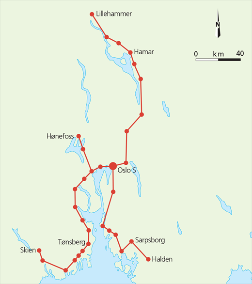
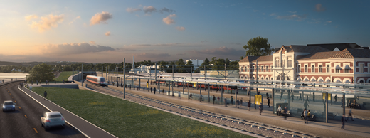
Known as the Intercity project, the new railway is designed for a maximum speed of 250 km/h (Figure 1). The 30 km section that runs from a timber terminal at Sorli by way of Stange and Hamar to Brumunddal is currently at the end of the municipal master-planning phase and is being developed by Rambøll Sweco ANS joint venture.
This paper describes the workflow in the preparation of the municipal master plan, which also includes environmental impact assessment and a technical master plan. It explains how the geographically distributed team made up of two companies and several sub-contractors co-operated and collaborated to reach the common goal of delivering a municipal master plan for governmental approval.
Using building information modelling (BIM) processes, the team focused the work on relevant tasks, involved important stakeholders as well as all team members, and stuck to a very tight time schedule. BIM as an integrated part of project management has proved a success. The BIM strategy was drawn up in the start-up phase and continued to be a central feature throughout execution. The importance of connecting BIM goals to project goals is discussed, as well as the importance of having a project management that assumes ownership of the BIM processes.
The development of BIM technology, cloud-based services and collaboration tools has changed collaboration between humans, and between humans and machines, which in turn has changed the way large infrastructure projects can be implemented.
2 Project background
The Intercity project is a programme of several major projects, the last of which is due for completion in 2034. Figure 2 shows the status of the project at July 2017 and the location of the section discussed in this paper. According to the government’s goals for the project, the railway to Hamar is due to be opened in 2024, and to Brumunddal in 2026.
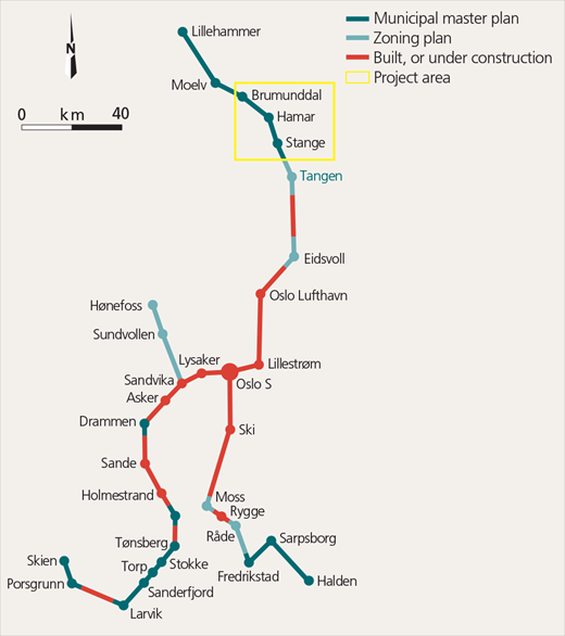
Status of Intercity network and location of Sorli-to-Brumunddal section (Bane NOR)
Status of Intercity network and location of Sorli-to-Brumunddal section (Bane NOR)
The 30 km section runs through downtown Hamar, a town located 125 km north of Oslo (Figure 3). The Intercity section between Sorli and Brumunddal is planned for sustained speeds of up to 250 km/h for passenger trains. The new line will be double-tracked, including sidings, through the towns of Stange (3000 citizens), Hamar (30 000 citizens) and Brumunddal (10 000 citizens). The line will pass through existing stations in Stange and Brumunddal, but in Hamar three alternative station locations were explored.
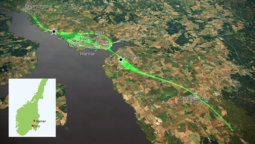
The 30 km section passes through valuable farmland, crosses an internationally protected bird sanctuary area and runs close to Mjosa, Norway’s largest lake, and protected historic railway buildings. It runs through three different municipalities – Stange, Hamar and Ringsaker – which means three parallel planning processes were needed.
The client demanded that construction of new tracks had to be possible while existing tracks were in daily and flexible use. The construction cost is estimated to be approximately €1·5 billion depending on the route chosen through Hamar.
The Ramboll Sweco team delivered 2400 documents in 1 year. Thanks to BIM, the optimisation period, in which the team worked on 12 different alternatives, lasted 3 months – it would normally have taken 1 year. The impact study, principal plan and technical plans were completed in just 7 months.
3 Key challenges
To plan a high-speed double-track railway in Norway will always be a challenge because of the country’s varying topography and the time-consuming, but important, democratic planning processes. Some of the most challenging issues that the Sorli-to-Brumunddal section had to deal with are described in this section.
Akersvika bird sanctuary (Figure 4) is an area protected by the Ramsar convention. This is an intergovernmental treaty that provides the framework for national action and international co-operation for the conservation and wise use of wetlands and their resources. Akersvika lies south-east of the centre of Hamar, and the existing railway passes the Ramsar area on a causeway and old railway bridge. When planning a new line, the project team had to minimise any impact on the protected area.
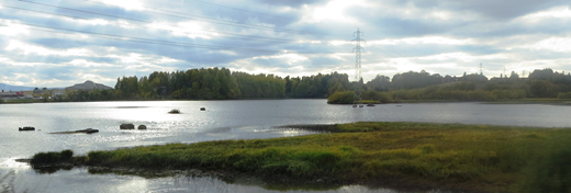
The route runs close to the Akersvika bird sanctuary (Erlend Bjørtvedt, https://commons.wikimedia.org/wiki/File:Hamar_aakersvika_IMG_1568.JPG)
The route runs close to the Akersvika bird sanctuary (Erlend Bjørtvedt, https://commons.wikimedia.org/wiki/File:Hamar_aakersvika_IMG_1568.JPG)
The line passes through some of the most valuable farmland in Norway. The project team had to find the optimal route and take measures to minimise and mitigate negative effects on the farmlands, while at the same time following the required curvature and shortest path for a high-speed railway.
In some areas, the track is located very close to central buildings, such as the city hall in Hamar and the historical, protected railway buildings at Espern in the centre of Hamar. The team had to find a compromise between the requirements set by a rigid line designed for high speed and the considerations needed for protecting important buildings.
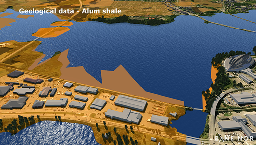
Figure 5 shows the location of alum shale in the project area. When exposed to air, alum shale swells, meaning it has to be sealed (e.g. with asphalt) during excavation. Alum shale also contains several toxic heavy metals that can destroy groundwater or kill fish and plants if it enters a watercourse.
Mjosa is the largest freshwater lake in Norway and is valuable as a recreation area. The new double-track railway will, according to Bane NOR’s recommended trace, follow the edge of the lake in Hamar. This means that the railway will create a visual barrier to Mjosa from the centre of town, as well as restrict use of the lake shore for recreation and residential use. The areas around the lake have also been flooded on several occasions in the past decades. A premise for the planning was to take into consideration a 200-year flood, and design water-resistant submerged tunnels as well as ensuring that the tracks remain above the critical level. This last requirement conflicts with the desire to minimise the visual barrier created by the railway.
Norway is a mountainous country and, though the topography for the Sorli-to-Brumunddal section is relatively flat, it is still challenging for a railway. Freight trains place strict limitations on gradient and high-speed passenger trains place strict limitations on curvature. The line has been placed in the terrain while taking into consideration three train stations, farmland and several vulnerable areas. Because of the topography, several tunnels need to be built.
Around the station areas, available areas for hub development had to be identified. It is a success criterion for the project that these areas will be functional and attractive. In Hamar, three alternative station locations were explored, which means that three hub-development plans had to be investigated.
The Sorli-to-Brumunddal project has many stakeholders that had to be either informed or involved. A thorough compliance plan was essential to ensure a valuable information flow and involvement of the critical stakeholders. Especially in the centre of Hamar, powerful stakeholders argued for their desired station locations out of the three options. This required good visualisation from the BIM model, and a well-crafted communication strategy to handle all three alternatives equally.
The client required the planning to make construction of the new tracks possible while existing tracks remain in daily use. This required an execution plan for the construction period to be completed in the early phase of the project.
The project team is composed of two companies (that in other cases are competing), Rambøll and Sweco, and several subcontractors. The team members are geographically spread out; they are in different office locations in Norway and also in other countries such as Sweden, Denmark, Finland and India. In addition, the client is also located in two different offices. The challenge with such a diverse organisation is to ensure information flow and that the whole team is on the correct track and heading in the same direction at all times.
4 Using BIM to meet challenges
Designing Buildings Wiki (2018) defines BIM as, ‘a very broad term that describes the process of creating digital information about a building or other facility such as a bridge, highway, tunnel and so on’. HMG (2012) defines it as a collaborative way of working, underpinned by the digital technologies which unlock more efficient methods of designing, creating and maintaining assets.
BIM as an integrated part of the project management has proved to be a success factor for the master-planning of the Sorli-to-Brumunddal project. From the project team’s point of view BIM is more than a digital three-dimensional (3D) drawing – it is a combination of technology and processes leading to state-of-the art project execution with collaboration between highly competent team members. Through collaboration helped by BIM tools and processes the project team was able to meet all the above-listed challenges.
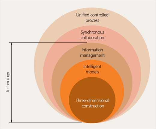
Figure 6 describes the distinct levels of a BIM system. The core of the system is the technology that must be present, with collaboration processes surrounding the technical core. The figure illustrates that a project team should work with a 3D model and also create intelligent models with information or attributes attached. Such information can include finishing materials, structural usage and cost. 3D models/drawings have been produced for a long time in infrastructure projects, but the information in the model has been and is still practically neglected.
The potential for enriching design models with attribute information has not yet been fully realised in the construction industry and has not been fully realised in this project. This is caused both by restrictions in the design software and by engineers and architects having to learn a new way of designing. In the Sorli-to-Brumunddal project, some information was attached to the objects for some discipline models.
The focus was nevertheless on geometry in the early phase. An Excel spreadsheet was used to gather information about the different discipline models, and the information was shown as tooltips in the common Autodesk Infraworks model. Examples of such information were model owner, model last updated and model content.
Figure 6 shows that BIM is not only about the model; it is also about synchronous collaboration and unified processes. The real aim of using BIM in a project is to ensure continuous inter-disciplinary collaboration.
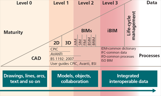
The UK BIM maturity model shown in Figure 7 categorises types of technical and collaborative work with respect to BIM. The model is an attempt to clarify BIM terminology and make it standardised and understandable for both suppliers and clients (BIM WP, 2011). The Sorli-to-Brumunddal project is clearly on level 2, combining different discipline models within one multi-disciplinary model.
4.1 How the project worked with BIM
The Sorli-to-Brumunddal project was defined as a model-based project by the client. This means that all design should be in 3D, and that models have priority over two-dimensional (2D) drawings. It also means that 2D drawings should be extracted directly from models.
In the start-up phase of the project, a BIM strategy was defined and agreed upon. It is important to establish a BIM strategy to ensure that the BIM goals support the project goals and that the focus is on the entirety of the project. The client was focused on using and detailing the BIM model further for every project phase.
The following list shows the project’s major goals for using BIM in the municipal master-planning phase
efficient communication by using the model
increased quality through inter-disciplinary insight
reduction of total cost through reduction of drawings and focus on entirety
innovation through importing reliability and safety into the model.
Table 1 lists details of the BIM strategy.
Details of BIM strategy
| Overall goals | Description of goal | Outcome | Measurement |
|---|---|---|---|
| Increased efficiency | The project team will use the BIM model to increase efficiency and reduce the number of misunderstandings. |
|
|
| Increased quality | Eliminate multi-disciplinary conflicts in early stages. Increase quality of decision underlay for decision makers. Consider future enterprise solutions. Ensure buildable solutions. Handle both entirety and details. |
|
|
| Reduced cost | Reduce production of drawings and consider other factors that may reduce the overall project cost. |
|
|
| Innovation | Importing Rams and HSE demands into the model. |
|
|
Rams, reliability, availability, maintainability and safety; HSE, safety, health and environment
The project team consisted of people from several different disciplines, working with several different types of software. Input from all the disciplines was needed for the common multi-disciplinary model – that is, the BIM model. In the start-up phase of the project the software for the BIM model was Infraworks, and the data flow from the different disciplines’ software was established.
The choice of software was based on the following demands on the BIM model
cloud-based, accessible for all project members
high performance when covering large geographical areas
high visual quality to ensure collective understanding of the project’s consequences
design review functionality
low-level interface on virtual reality functionality and navigation
functionality for making quick 3D illustrations and movies.
These demands are characteristic for an early project phase. A more detailed project phase, for example construction, will have other demands such as technical collision control and attribute handling.
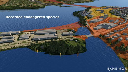
The principle of one model means that all disciplines must provide input to the BIM model either by design review and/or by specific or abstract objects. Traditionally, a BIM model is made up of all the ‘hard core’ technical disciplines – such as railway, construction and roads. The soft disciplines – such as area planning; environment; reliability, availability, maintainability and safety (Rams); and safety, health and environment (HSE) – have traditionally not provided input to the model. One of the project’s BIM goals was to include such abstract demands and objects in the model. Figure 8 is a 3D visualisation from the model showing how registration of red-listed species has been added by the environmental discipline. Both the project team and client were urged to provide input to the model through the design-review process.
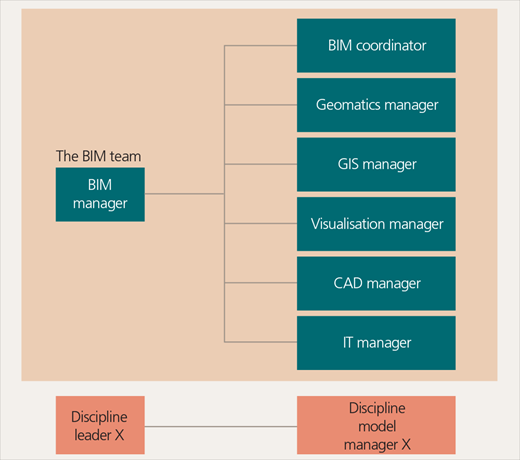
A BIM execution plan was established at the outset. The plan described BIM roles in the project (Figure 9), routines for base data, nomenclature for files and layers, the model list, the exchange formats, software and installation information for multi-disciplinary models, the BIM cycle, the design-review process, and templates and layout for drawing production. The plan is the most critical tool for ensuring that the whole project team succeeds with the BIM workflow.
To ensure the project team had the right focus at all times, a BIM cycle tightly connected to the project meeting plan was established (Figure 10). As the figure shows, the cycle repeats itself every 14 days, as follows.
Day 1: project meeting with information from project management, project status review, design review in model and visual planning. All tasks to be carried out or followed up on are collected in one log, which is continuously updated during the whole project period. Tasks to be solved by the means of integrated concurrent engineering (ICE) meetings are identified, and ICE owners are pointed out.
Day 2 and 8: ICE meetings are arranged. Fixed days are set to ensure that the required resources are available.
Day 5: main discipline model is delivered.
Day 9: other discipline models are delivered.
Day 11: multi-disciplinary model is updated.
Day 12: all disciplines give input to the design by means of commenting in the model using the Design Feed tool. Issues to be handled at the next project meeting must fulfil the following requirements: the issue must be relevant for more than one discipline, have a significant consequence for area use, have a significant cost consequence, and potentially cause a ‘show-stop’ (objection).
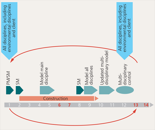
BIM cycle in the project. PM, multidisciplinary meetings; SM, integrated concurrent engineering meetings
BIM cycle in the project. PM, multidisciplinary meetings; SM, integrated concurrent engineering meetings
The design-review process was described for the project team in the BIM execution plan but was also available as a short video. The aim of the design-review process is to ensure quality control with respect to the interface between the disciplinary models. This should in the end contribute to ensuring that the public plan is feasible with respect to technical challenges within the area plan boundaries.
The team members had to write comments following a strict naming convention to make sorting and categorisation possible. Each 14th day the comments were saved as a pdf file to keep as a back-up and as documentation of the multi-disciplinary quality control. The design-commenting tool in the software is still immature, and the project experienced challenges going through the comments during the meetings caused by non-existent sorting routines in the software. Most of the disciplines nonetheless used the software as described, and contributed to ensuring high quality in the inter-disciplinary design process.
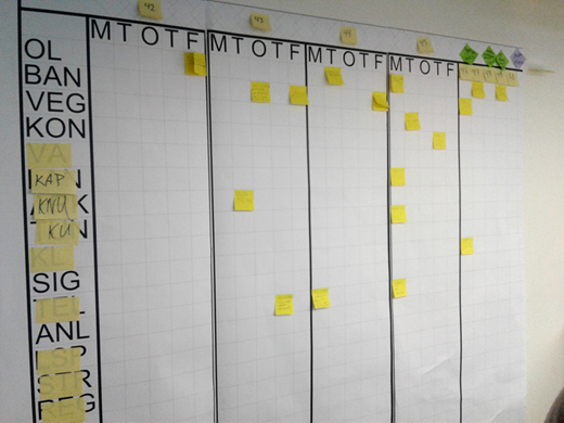
Visual planning is a tool used in Lean methodology (LEI, 2018). The core idea is to maximise customer value while minimising waste. In simple terms, Lean means creating more value for customers with fewer resources. The project team used visual planning as part of the project meeting each 14th day. The team developed the routine throughout the project period, and will develop it further in the next project phase to make it more flexible for virtual meetings. The governing principle for visual planning is to get each team member involved in the planning of his or her own deliverances and deadlines, and to identify dependency relations to other disciplines. The main questions to be answered are what do I deliver, and when; and what do I need from other disciplines, and when?
Post-it notes in assorted colours were used for the process, and the focus was on the next 4–6 weeks. Each Post-it note was placed in co-operation with the disciplines involved (Figure 11). The result of the meeting was digitised into Excel after the meetings.
ICE is a methodology that demands well-prepared work sessions in which specific tasks are to be solved. The Sorli-to-Brumunddal project used the ICE methodology in the 14-d cycle. Attendees at the meetings were hand-picked for each session, and also included decision-makers to ensure short decision paths. The meetings always had specific goals and required decisions to be made during the meetings. Meeting attendees were expected to meet physically – virtual attendance was accepted only in exceptional cases.
The BIM model was central in the meetings both as a communication tool and as a work tool, when the ICE subject required design to be executed during the meetings. The ICE meeting methodology promoted inter-disciplinary co-operation and quality. It also required that all attendees were well prepared and provided input during the meeting. ICE sessions were in worst cases terminated if one or more of the attendees were not prepared. The meeting room facilities were also important. ICE sessions often took place in so-called ‘big’ rooms. These were rooms equipped with two or more TV screens, one smart board, good audio-video technology, and access to wi-fi, power and screen-sharing for all attendees. In addition, nearby meeting rooms were accessible to allow team members time out during some sessions that were irrelevant to them, or to work in silence if needed.
The experiences from use of the ICE methodology in the project were positive. The project team reported, in a user survey, that the ICE methodology resulted in termination of hanging tasks and efficient multi-disciplinary clarifications and decisions.
Two important BIM roles in the project were the geographic information system (GIS) manager and geomatics manager. All base data in the project had to be controlled and verified by the geomatics manager to ensure that base data were of high quality. This included both existing base data and land-survey data gathered for the project. The geomatics manager was also responsible for producing accurate terrain models and other models of existing situations in co-operation with the rest of the disciplines.
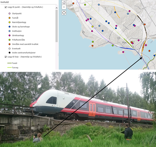
The GIS manager had established an ArcGIS geodatabase for GIS analyses, production of map illustrations and field registering using the ArcGIS online tool. Figure 12 shows how the project’s landscape architect used the online tool to register farms, wells and other points of interest. The results of the registrations were imported into the BIM model.
The BIM team also had a visualisation manager. The most important project goal for this phase was to get the plan adopted by the municipalities. Achieving this goal required an effective communication strategy and high-end visualisation products, in addition to professional engineering. Using the BIM model as a base, many 3D illustrations, photograph montages and videos were produced in addition to the virtual reality model produced in the BIM model. These products were used by local newspapers, national television channels, social media, newsletters and public meetings. They were invaluable instruments for achieving a common understanding of a complicated project (Figure 13).
4.2 Innovation through BIM
The word ‘innovation’ originally comes from the Latin innovare, which means to renew or create something brand new. The Sorli-to-Brumunddal project has been recognised as a project doing just that. In November 2016, the project received an international BIM award at Autodesk University in Las Vegas in the category ‘large infrastructure projects’. The following innovation drivers led the project to such a prestigious award
a demanding and ambitious client
project management with a will to change: new software, new process tools and types of meetings
dedicated and enthusiastic project members.
The last of these points is arguably the most important. All project members were important in order to complete such a complicated project. The experience from the project is that when people get to know each other through physical meetings and milestone parties, they can create amazing collective results. This requires structured and empathetic project management and a trustful client.
The project continues to work with innovation. While this paper was written, Trimble Quantm software was being explored to automate the search for feasible alternatives with better environmental and public outcomes. In addition, issue and tracking software JIRA was being implemented to collect, categorise and prioritise all the actions carried out and decisions made in the project. The issues arise from different sources, for example design-review processes, internal and external meetings, visual planning and stakeholders.
4.3 Value added to the project
The Sorli-to-Brumunddal project team handled information with a very high level of complexity in one multi-disciplinary model. Combining monetary impacts and non-monetary impacts in one model provided a powerful tool for identifying traces that would serve as compromises between building costs and environmental costs. The project team continuously increased the maturity of the project by moving the track or adding mitigating measures in an iterative process.
Feeding the multi-disciplinary model with more than 50 different discipline models gave an excellent overview of interfaces and needs for follow-up meetings on certain themes. It also revealed needs for modifications of certain discipline models, and kept the inter-disciplinary quality in focus continuously throughout the project period.
The client had full insight into the multi-disciplinary model throughout. The project team believed in an open dialogue with the client and involved the client in the development of the project. This provided a valuable means for quality control throughout the project period, and reduced or avoided misunderstandings and delays.
Collaboration and meetings with authorities and important stakeholders were also important sources of information for the model. The complete model was presented to the stakeholders, giving them a full overview of impacts and a visualisation of the project, thus finally making them able to make qualified evaluations of the different alternatives.
5 Conclusion
Planning a high-speed railway in Norway is complicated. By using BIM all the project members co-operated and provided knowledge to the project. A large-scale project like this requires co-operation with competitors. When everyone shares knowledge, the whole industry benefits, further developing methods for smarter project execution.
The public knows that robots or machines will eventually replace their jobs. One can see this as a threat, but human creativity and the ability to solve complex tasks together cannot be replaced by a computer or a machine. The value created from simply working in a team of two or three, instead of working alone, is immeasurably greater than the sum of the individual contributions. Success within digitalisation lies in the intersection between technology and the creativity and knowledge of humans. This is what the team involved in the Sorli-to-Brumunddal project experienced.

Acknowledgements
The authors would like to acknowledge the client, Bane NOR, for being forward-leaning and co-operative with regards to the BIM processes in this project. The authors would also like to acknowledge their co-operation partner, Sweco, for contributing to knowledge-sharing and a good team atmosphere.
