

This visit report describes a site visit to Itaipu dam, the largest hydroelectric plant in the world in terms of output capacity. The paper describes the overall layout of the dam and describes the extensive instrumentation used for monitoring. The dam, constructed between 1975 and 1982, straddles the border of Brazil and Paraguay and is jointly owned by the two countries under a unique arrangement which required a special treaty. The dam structure is composed of six different dams each of which was designed to minimise construction costs for the overall dimensions required. The dam is heavily instrumented with over 2000 instruments in total, most of which are manually read. These demonstrate that, after an initial period of settlement, the dam has been fairly stable. The catchment has also proved an extremely reliable source of flow and the dam has successfully passed significant flood flows.
Introduction
An International Water Association conference in Sao Paulo offered a chance for me to visit some other parts of Brazil and I opted for Iguasso Falls, which were only a short flight away. While in the area, I made enquiries about visiting Itaipu dam. In addition to the regular tourist visit, I was able to meet with operational engineers who are responsible for the day-to-day monitoring of this huge installation.
Background
Itaipu dam, which lies on the Parana River, is jointly owned by Brazil and Paraguay. It is the largest hydroelectric power plant in the world in terms of output, although the Three Gorges dam has since overtaken it in terms of installed capacity. It is one of the largest dams in the world and was constructed between 1975 and 1982. It operates under a unique legal set-up: neither a public limited company nor a government-owned corporation but operating through a specific treaty set-up between the two owning countries. This treaty ended centuries of conflict over the area and since then a further treaty with Argentina has seen agreed river levels, land and water use for the area.
It has an installed capacity of 12 600 MW, enough to supply a city of 2·5 million inhabitants and in fact supplies nearly 100% of the energy used in Paraguay and 20% of that used in Brazil. The construction was jointly funded and it is estimated that the value of the energy generated will enable the loan required to be paid off in 2023.
Construction
The overall structure is built on volcanic rock, principally dense basalt with a number of layers of breccia and consists of six different dam structures along with overflow and powerhouse installations. The construction was a major feat of logistics with around 40 000 workers on site and up to 5000 workers being recruited every month between 1978 and 1981. Over 20 000 trucks and 6000 railway cars were used and the infrastructure for the town that was built to house the operation remains and has formed a new urban centre for the region.
The main dam is a hollow gravity dam 612 m in length built of mass concrete with reinforced buttresses at intervals (Figures 1 and 2). The walls are 10 m thick at the top and increase to a maximum width of 20 m and the dam has a maximum height of 96 m, containing 4·4 Mm3 of concrete in total. The maximum amount of concrete laid in a day was 7027 m3, the concrete being placed using seven aerial cables. Ice was mixed with the concrete to control the heat of hydration and reduce cracking.
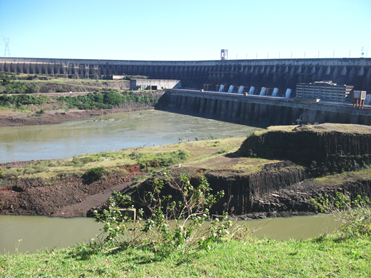
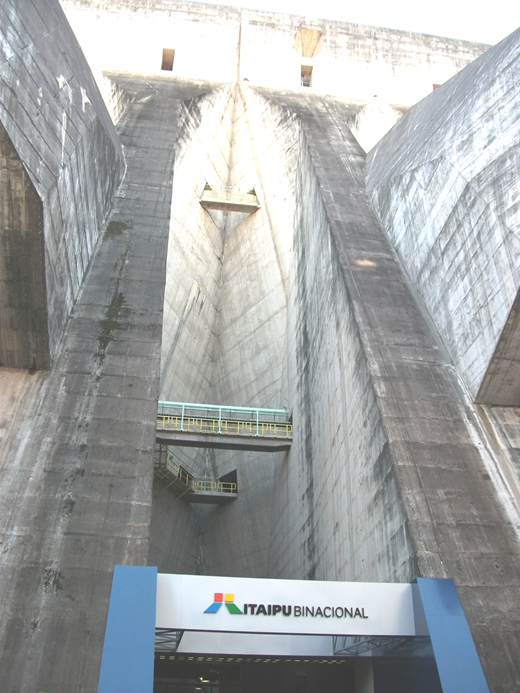
Close-up of the downstream face of the main dam showing the reinforced buttresses
Close-up of the downstream face of the main dam showing the reinforced buttresses
The other dams completing the complex include, on the left-hand side of the main dam, a 30 m earthfill dam 2294 m in length, a 70 m high rockfill dam with a clay core 1984 m in length and a buttress dam, connected to the main dam by a 170 m high gravity diversion dam. On the right-hand side of the main dam either side of the spillway is a smaller earthfill dam, 25 m high and 872 m in length and another buttress dam 1438 m in length with a maximum height of 85 m. Each dam structure is designed to minimise costs within the size parameters. The total length of all the dams is over 6300 m in length and used over 12 Mm3 of refrigerated concrete along with 15 Mm3 of rockfill, 6 Mm3 of clay and 481 000 t of steel.
A 2 km diversionary channel, 150 m wide and 90 m deep, was built for the river with two temporary arch dams protecting the construction site. This required moving 55 Mm3 of earth and rock and was completed in October 1978. When the main installation was complete the two temporary dams were demolished but the remnants of one can still be seen (see foreground of Figure 1).
Hydrology and spillway
A 1·5 m deep stilling pond dissipates the energy from the spillway which is built in three sections from mass concrete. The total spillway capacity is 62 200 m3/s, dropping over 60 m from the top of the sill, and it is 36 m long by 483 m wide. Fourteen ‘Tainter’ gates control the flow through the spillway. These gates are 21 m high with a radius of 20 m (Figures 3 and 4).
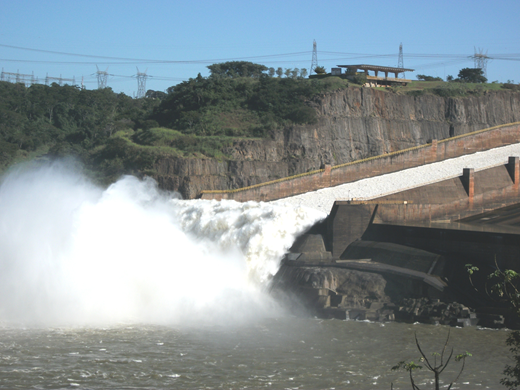
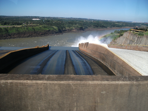
The average flow in the Parana River is 11 680 m3/s with a maximum recorded flow of 33 000 m3/s in June 1983. The flow has remained very reliable with the recorded minimum in August 2001 of 6 000 m3/s and flows of over 8000 m3/s 90% of the time. The average rainfall in the catchment area, which is over 500 km2, is over 1650 mm. Thus the river provides a very reliable source of energy to the two countries.
It was originally estimated that the lake created by the dam would take 90 days to fill, but shortly after completion exceptional rainfall and extensive flooding meant that the lake was filled in only 2 weeks.
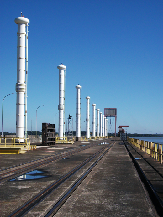
Control of flow through the generating plant is provided by actuated gate valves with an additional stop-log facility (Figure 5). The intakes are protected by screens, cleaned using mechanical rakes, and streamline flow is promoted by way of hydrodynamic beams across the inlet.
A 10 km spawning channel provides the facility for fish to pass the dam and is also used for recreational purposes. It was designed to create an architectural feature in itself and forms a focal point for part of the parkland surrounding the dam. The sustainable aspects of the energy generated are emphasised and the area has become a centre for conservation innovation and eco-tourism.
Instrumentation
A team of 15 civil engineers is employed to monitor the structure. Much of the work requires manual reading and visual inspections with over 5000 drains and 2000 instruments to oversee. The majority of issues were identified in the first 2–3 years with a few minor cracks appearing which were treated with epoxy grout. There is some infiltration, around 150 l/s, from the abutments and foundations but the flows in all the drains are very consistent.
A total of 916 of the instruments are located in the foundations, with 664 piezometers to measure the uplift at various points, 32 water level recorders, 136 extensometers to measure the rock mass deformation and a number of tri-orthogonal deflection meters measure the relative movement between sets of joints. Some 50 discharge weirs measure the flow of water collected from drainage systems. Settlement meters measure the movement within the earthfill structures.
The concrete is also heavily instrumented with 1347 instruments in total. 261 strain meters are used to measure the deformation of the concrete and from that the stress in the concrete is calculated with a further 82 stress meters directly measuring the tension in the concrete. Fifty-eight electrical joint meters measure the opening and closing of joints whilst 139 thermometers measure the temperature both inside the concrete and on the surface. Further movement monitoring is carried out using pairs of pins and extensometers. Pendulums are used to measure the rotation of the different concrete blocks and the crest deformation as well as shear deformation in the foundations.
Every 4 years an international board of consultants inspects the dam and reviews all the data collected.
Conclusions
The scale of this project is dramatically different from even the largest dams in the UK and the visit offered a unique opportunity to learn about the construction and monitoring of a vast structure, as well as how an international project could be conceived, implemented and managed. The location has become a focal point for sustainable industry and is used to maximum effect as a vehicle to promote the two owning countries. The tourist and educational opportunities for the site have been optimised and there are perhaps lessons for the UK in how the engineering aspects of the installation are described in a simple and dramatic way.
In spite of the language difficulties it was possible to learn a substantial amount both during the tourist circuit and the subsequent discussion with the monitoring engineer. My visit showed that continuing professional development is possible in the most unlikely places and one can extend one's knowledge at any time.

The author gratefully acknowledges the time taken by Mr C. Gomes, from the Public Relations Division to arrange the trip and meetings, and the patience of my long-suffering husband who endured a detailed explanation of dam surveillance while on his holiday.

