After its completion in 1929, the Echelsbacher Bridge in the alpine foothills of Bavaria (Germany) was an internationally renowned engineering achievement. Built in the Melan design, this was the largest Melan-type arch bridge of its time. Due to environmental influences over time, the bridge has reached an unsafe and structurally hazardous state. This paper describes the history and the details of the bridge and the investigations carried out for its structural safety verification. It was shown that this structural heritage has reached the end of its life cycle; therefore, the decision was made to replace it. The new bridge design well integrates this historical and technical monument.
1 Historical background
The Echelsbacher Bridge in the alpine foothills carries the federal highway B23 over the River Ammer, which flows from the Ammergauer Alps into the Ammersee (Lake Ammer). The bridge is located between the communities of Bayersoien and Rottenbuch. In a spectacular manner, it spans across a 75 m deep canyon, with steep canyon walls, cut by the River Ammer into the landscape.
Over this stretch, the road is part of an ancient Roman trade route from western Germany to northern Italy via the Brenner Pass. The historical route crossed the River Ammer in the valley over a small bridge reached by the Echelsbacher Steige (steep road).
In the late nineteenth century, this route was found to be no longer sufficient for the traffic requirements, especially because during the winter months, motorised vehicles had difficulty climbing the steep access routes (with a 20% slope) on their own.
After multiple political attempts by interested lobbies, the local Roads and Rivers Authority of Weilheim held a competition in March of 1928 for construction companies based in Bavaria, with experience in large bridge construction (Düll and Gerhardt, 1931). A further reason for the decision to build the new bridge at that time could have been to improve the infrastructure for the 300th anniversary of the world-famous Oberammergau Passion Play in 1934.
Companies were invited to tender an offer within 3 months for a design, which had to include a proof of stability of the bridge and a binding offer. In the invitation to tender, it was required that the bridge should meet the bridge standards according to Classification I, defined in the Industrial Standard DIN 1072:1925 (DIN, 1925). Additional load specifications were supplemented regarding the temperature loads.
A total of 25 teams, composed of construction companies, freelance engineers and architects, submitted applications. The tenderers submitted 50 designs which showed the whole bandwidth of the contemporary major bridge construction technology, including 36 reinforced concrete bridges, 13 steel bridges and 1 unreinforced concrete bridge.
The first prize was awarded to Ways & Freitag, with their design of a multiple arch bridge. However, the project was awarded to the runner-up, a team composed of the construction company Hochtief Aktiengesellschaft, the engineering company Streck & Zenns and the architect Wilhelm Kahrs.
This decision was made by the Bavarian Ministry of the Interior for Building and Transport for reasons of economic policy and considering the planned cost of 645 000 Reichsmarks = €8 760 000.
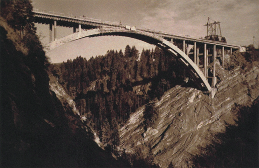
The central element of the design was a 130 m wide reinforced-concrete arch with a stiff reinforcement. This construction, known as Melan construction, describes a concrete cross-section with an integrated steel framework, which is initially used as the bridge’s falsework. The Echelsbacher Bridge was the largest Melan-type arch bridge in the world (Figure 1).
After World War II, four series of major structural maintenance measures were necessary on the bridge. These were the widening of the vehicle lanes by adding cantilever slabs along the sides (1963), changing the joints in the deck slab (1973), basic rehabilitation (1983) and repairs of the caps, bearings and expansion joints (2001).
Based on the outcome of the structural inspection and additional calculations, plus the requirement to handle increases in traffic, it was decided in 2013 to launch the competition for a new construction project.
2 Melan–Spangenberg construction
The Echelsbacher Bridge was built using the Melan–Spangenberg design, named after its developers Joseph Melan and Heinrich Spangenberg. This construction method is no longer very common.
At the end of the nineteenth century, an Austrian civil engineer and professor at the polytechnics of Vienna, Brno and Prague, Joseph Melan (1853–1941), developed the original construction design, which was named after him (Eggemann and Kurrer, 2006). The main feature of this construction is the erection of self-supporting steel framework, around which the formwork is built, so that the concrete encloses the steel framework. During the construction, the steel framework serves as a falsework and afterwards as an integrated reinforcement. Originally, this technique was used in the construction of ceilings, for which Melan got a patent in 1892.
The engineer Fritz von Emperger (1862–1942) introduced this technology in the USA, which spread even more widely in the early twentieth century than the steel reinforcement using round steel rebars.
In 1924, there were approximately 5000 bridges using this technology (Eggemann and Kurrer, 2006). However, this technology was suitable only for structures with relatively small widths, because the steel structure was prone to deformation during the pouring of concrete. In larger structures, with larger concrete segments to be cast, the concrete was already hardening in the first segment, before the casting was completed; this resulted in severe cracking in the young concrete.
A professor of bridge engineering at the Polytechnic of Munich (Technische Hochschule, now known as Technical University of Munich (TUM)), Heinrich Spangenberg (1879–1936), introduced a decisive improvement for arched structures by charging the steel construction with a gravel filling before the casting of concrete. With an equivalent weight to concrete, the gravel filling evenly loaded the steel framework and was emptied when the concrete was poured into the respective segments. This way, the deformation of the steel framework during concrete pouring was avoided. This development is known as the Melan–Spangenberg construction, which was first used during the construction of the Echelsbacher Bridge.
The Melan–Spangenberg construction is especially suitable for arches and has many advantages.
The steel framework is first a falsework and later, reinforcement for the finished structure.
The steel is pre-stressed by the weight of the concrete, which is a positive effect for tensile forces of the steel due to traffic loads (pre-stressing increases due to the time-dependent deformations of the concrete).
The concrete section is a good protection against corrosion.
Compared to a pure steel cross-section, this cross-section is stiffer, thus, more advantageous under traffic load.
It also has the following disadvantages.
The internal steel construction cannot be inspected.
The bonding properties between the steel framework and the concrete are undefined.
Under shrinkage and emanating heat of hydration, the concrete will suffer cracks due to the stiff framework and the imposed deformations.
The steel framework fills the formwork to such an extent that casting becomes difficult and can result in faults in the concrete.
The use of the steel is quite uneconomical because the steel construction must be designed for the dead weight of the concrete of the arc.
Nowadays, this construction technique is no longer applied, but there are examples where a prefabricated steel formwork has been cast in, but is not considered as a reinforcing element.
3 Construction of the Echelsbacher Bridge
The static system of the Echelsbacher Bridge is a dual arch that supports the roadway construction. The two arches are connected by transverse braces. The arches are supported by rotational bearings, placed on a flat-grounded foundation. The total length of the bridge is 182 m.
The original width between the railings was approximately 8·30 m, and the height above the valley floor is 75 m. The arches have a box cross-section with a wall thickness of 0·35 m. In the corners of the cross-section, the walls are haunched; they have a constant width of 1·50 m. The height varies between 3·20 m at the base and 2·0 m at the middle of the arch.
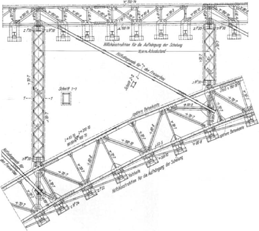
The steel framework was set up as a free-standing cantilever structure, consisting of riveted rolled L-profiles and flat steel strips (Figure 2). The entire steel construction is composed of not only the arches, but also the spandrel columns and the beams for the roadway construction. The composite construction of the spandrel columns and the roadway deck was not described in the competition tender, but was intended to facilitate the cantilever construction method for the erection of the bridge, as shown in Figure 3.
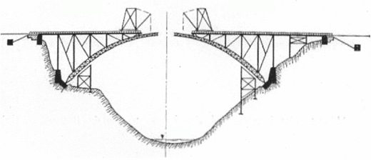
During the construction, the roadway deck acted as the tie, and the spandrel columns were part of the steel framework, complemented by temporary diagonal braces. This way, the entire steel structure was a huge framework, built from both sides of the valley to meet in the middle. The alignment of the framework was achieved by means of hydraulic presses, arranged behind the roadway abutments and below the arch abutments. This way, the finished arch halves were adjusted so they met precisely in the middle.
After the two framework halves were joined in the middle of the valley, the formwork was installed so that the gravel could be filled in to pre-stress the arch. As the concrete for the arch was cast, the respective amount of gravel was removed, so the weight on the arch remained constant (Figure 4). Upon completion of the arch, the spandrel columns and roadway deck were cast.
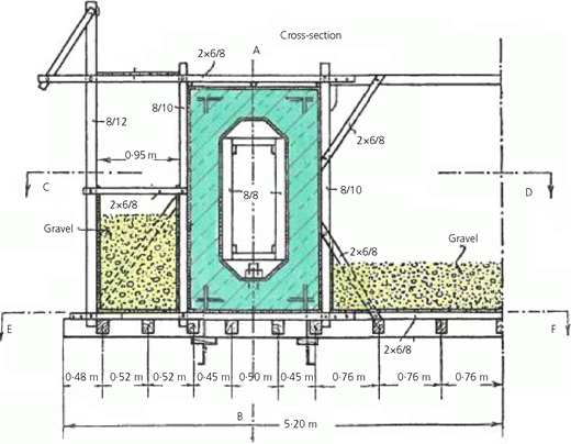
Cross-section of the arch with formwork filled with gravel (Düll and Gerhardt, 1931)
During the actual construction work, the roadway deck had to stretch over all elements to carry the tensile forces. In the finished bridge, Gerber joints were inserted to ensure a statically determined construction.
The steel profiles of the framework construction were uncoated, except for the contact surfaces between the riveted flat strips, which were protected against corrosion. The remaining surface was left unprotected, to improve the bond between the steel and the concrete. The roadway deck and the secondary longitudinal beams of the roadway deck, as well as the braces between the two arches, were reinforced with steel rebars.
The total project time was 13 months. In October 1928, the company started with the final design and preparation of the construction site. Two months after beginning with the static calculations and drawing, steel was already ordered and the work started in Kaiserslautern. The foundation and the abutments were constructed concurrently. The erection of the steel frame began in April 1929, and the bridge was completed in August of that year.
In the late 1920s, engineers worldwide did not have a lot of experience with concrete constructions as large as the arch of the Echelsbacher Bridge. Technologically, there was still a lot of experimentation and innovation going on in concrete construction. The relevant standards had only recently become available. The following two major requirements were defined for concrete.
First, a sufficient and reliably achievable strength was necessary, and second, the concrete needed to be filled in the limited spatial conditions of the steel construction.
All involved were aware of the relationship between the water–cement ratio and concrete strength; yet, a higher water–cement ratio improved workability.
For the purpose of finding the perfect concrete composition, several tests were conducted. The following concrete composition was selected
gravel: 1070 kg/m3
sand: 715 kg/m3
cement: 340 kg/m3
water–cement ratio: 0·60
slump: 60 cm.
At present, the water–cement ratio of 0·60 is considered insufficient to provide the required durability, according to today’s technical standards. At the beginning of the last century, there was little experience regarding the importance of concrete durability.
The grain size was classified as medium fine. The concrete was mixed on site. Tests of the concrete were performed on 7 d old specimens. There are no records of these test results available. The tests were carried out by the laboratory of the Polytechnic of Munich (today known as Materialprüfungsamt für das Bauwesen of the TUM).
Contrary to concrete construction, which was considered a new technology in the early twentieth century, steel construction was a well-established technology. All over the world, there were already steel bridges, superior in size to the Echelsbacher Bridge.
For the construction of the steel framework, steel grades of St 48 and St 37 were selected. To ensure steel quality; tests were conducted at the laboratory of the Pfälzischen Landesgewerbeanstalt in Kaiserslautern.
4 Repairs and rehabilitations
In 1948, 20 years after the initial construction, the first repairs became necessary, because of the spalling of concrete due to frost and weathering of the cornices. The work was carried out by the road authority, with support from the mountain rescue organisation.
In 1964, following substantial material deterioration due to climatic influences and effects, major repairs to the bridge became necessary. There was damage to the concrete surface of the roadway deck; the joint construction was faulty; the roadway cover had corrugations and shoving; and the seals were found to be leaking. The arches, however, were rated as well preserved.
In addition, widening of the bridge deck with sidewalks was intended, so that pedestrians could have a view of the valley below (Figure 5). Therefore, the cantilever slabs needed to be replaced. A solution proposed by the company Philipp Holzmann AG was selected. The existing cantilevers were mechanically removed while maintaining the original reinforcement. Then consoles were mounted with a spacing of 2·7 m. Over these consoles, an in situ concrete slab was cast.
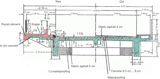
Cross-section of the deck before (right) and after (left) the widening (Schmerber and Gantner, 1966)
Cross-section of the deck before (right) and after (left) the widening (Schmerber and Gantner, 1966)
The consoles were fastened to the longitudinal beam by two steel rebars and a mechanical fastener. The contact surfaces in the pressure area, between the cantilever and the longitudinal beam of the road deck, were mechanically prepared and glued in place with epoxy resin. This can be considered the first application of epoxy resin to a supporting structure in bridge construction.
The roadway cover, consisting of isolation, protective concrete and asphalt, was completely removed and replaced by a copper waterproofing layer and mastic asphalt. The surface of the roadway construction was found not to be damaged significantly by environmental influences (Schmerber and Gantner, 1966).
Ten years later, in 1973, it was found that the joint constructions were unsatisfactory. The gaps in the Gerber joints were found to have an insufficient deformation capacity. As a solution, two of the four Gerber joints were widened to allow the measured movements while the other two were closed. The widened joints were equipped with sophisticated roller bearings. To support the roller bearings, new consoles had to be constructed. These were fastened and tightened to the neighbouring supports by post-tensioning bar tendons. Above the gaps, the joint transition constructions were inserted. The 10-year-old road surface was also replaced during this work.
In the years 1983–1985, a general rehabilitation was carried out. Contrary to the previous inspections, this time, additional damage to the concrete of the roadway deck and the arches were detected (cracks, spalling and corrosion of the steel rebars). For the first time, chloride ions were identified as the cause of the severe corrosion. This was related back to the use of de-icing salt by the road authorities from the end of the 1960s.
Because the roadway surface was not sufficiently sealed, water was able to penetrate through the deck and reach the rest of the structure, including the spandrel columns and the arches (Grundner, 1966).
The repair of the roadway surface was carried out while redirecting the traffic onto one lane. Damaged concrete was removed by means of high-pressure water jetting. The concrete surface was then replaced with a polymer-modified screed. To improve the drainage properties of the surface, additional drop spouts were installed.
The arch surface was completely cleaned by high-pressure water jetting. Concrete faults were repaired with concrete injections. Finally, the entire surface was covered with a coating.
At the time of all this work, the current regulations concerning repairs were not applicable. On the whole, it may be safely assumed that the repairs carried out on the Echelsbacher Bridge were a pioneering achievement in the field of concrete repairs and renovations. All repair measures were scientifically accompanied and inspected by Professor Springenschmid of the TUM (formerly Polytechnic of Munich).
In 2001, additional repair work became necessary; this time, on the roadway surface, the expansion joints, the bearings and the railings.
In summary, it may be stated that extensive repair work is necessary every 10–15 years. Climatic influences are mainly responsible for the damage. Furthermore, because of the intense use of de-icing salts, the environmentally influenced damages have considerably increased in the recent past.
5 Structural inspection
In 2011, the State Building Authority of Weilheim commissioned the engineering office Zilch + Müller Ingenieure with a basic assessment of the state of the Echelsbacher Bridge, including the calculation of the structural safety and an extensive structural inspection of the bridge according to DIN 1076:1999 (DIN, 1999).
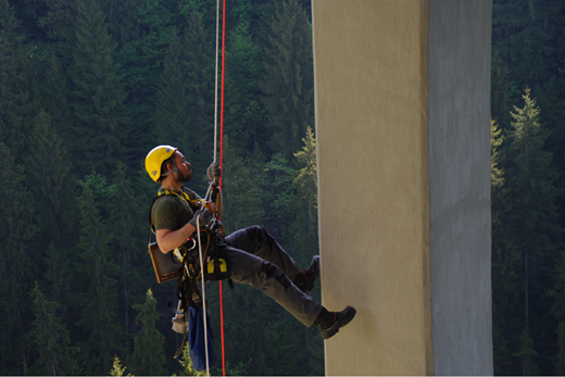
Due to topographical circumstances, the majority of access to almost all structural components was through the roadway deck. The roadway construction and parts of the arch could be inspected using a truck-mounted underbridge access platform; the other parts of the arch and the spandrel columns were inspected by abseiling (Figure 6).
The 2011 inspection resulted in a structural rating of 3·0, according to bridge inspection guideline RI-EBW Prüf 2013 (Bundesministerium für Verkehr, Bau und Stadtentwicklung, 2013). The rating defined in RI-EBW Prüf varies from 1·0 to 4·0. A bridge with a rating of 4·0 is unsafe. Basically, this was because of the damage which affected the durability of the structure. This was the typical kind of damage found on reinforced concrete road bridges.
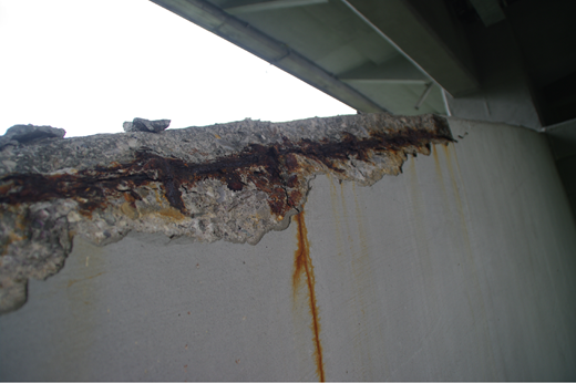
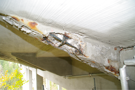
The areas of damage are distributed across the entire structure. The damages include concrete spalling; delamination of the concrete cover exposing the reinforcement; corrosion of the steel rebars (in some places, completely dissolved the cross-section of the rebars); and corrosion of the steel framework with a significant reduction of the steel cross-sections.
One decisive point of inspection and assessment is that the steel construction cannot be visually inspected. Due to the missing external corrosion protection and the increased probability of corrosion, this is intrinsically critical.
Another critical issue concerns the cantilever beams, which were installed in 1963. These are critical because the consoles were installed only by single steel rebars, and there is no redundancy for failure. Other critical issues are the connections between the braces and the arches because the reinforcement is certainly insufficient and concrete spalling will lead to a reduction of stability and load capacity.
In the subsequent material tests, samples were taken locally
core samples to determine the concrete strength
coring concrete dust samples to determine chloride content
cutting samples of the steel framework locally to determine the mechanical steel characteristics.
Core sampling needed careful planning because any damage to the embedded steel framework had to be avoided. These circumstances limit the number of test locations without the risk of seriously damaging the construction. The coring locations were planned with accurate and non-invasive reinforcement detection methods. Because of these circumstances, the number of core samples is very limited. The results of the testing are shown in Table 1. The maximum percentage of chloride ions is 5·8% of the cement weight measured in a depth of 60 mm in parts of the roadway construction. Carbonation is not so critical.
Results of testing the concrete strength
| Specimen | ∅: mm | Length: mm | Density: kg/m3 | Strength: N/mm2 |
|---|---|---|---|---|
| BK1 | 99 | 100 | 2470 | 37·2 |
| BK2 | 99 | 100 | 2360 | 48·9 |
| 1A | 98 | 98 | 2400 | 63·6 |
| 1B | 98 | 98 | 2420 | 59·6 |
| 1C | 98 | 97 | 2380 | 53·7 |
In all steel samples, the characteristics according to the planning specifications were recorded and confirmed. On the basis of the inspection results and assessment, the road construction authority agreed to inspect the Echelsbacher Bridge biannually.
The most recent inspection was in the summer of 2015. An increase in the number of defects was documented. The continuing deterioration of the structure was obvious (Figures 7 and 8).
6 Static calculations
The Melan construction is not regulated by any guidelines. Therefore, it is not covered by the guidelines for structural assessment as prescribed by the Federal German Ministry for Traffic (Bundesministerium für Verkehr, Bau und Stadtentwicklung, 2015). For the structural assessment, it was necessary to perform calculations on the basis of structural mechanics.
Calculations of the cross-sections on the basis of accepted regulations for steel–concrete composite constructions cannot be used because of the lack of steel connectors. The bonding properties between the profile steel material and the concrete are undefined. In modern composite structures, special bonding means, such as shear studs, are used to secure the composite construction.
The construction of the bridge (erection of the framework, preloading of the steel framework with gravel before casting) must be simulated correctly. The time-dependent deformations of the concrete (creep and shrinkage) are relevant, because they significantly influence the internal stresses within the steel framework and the concrete. In the analysis, creep and shrinkage are modelled with the model defined in EN 1992 (DIN, 2011). Creep and shrinkage could be calculated for every construction step.
For the static calculation, the steel framework construction and the concrete construction are modelled separately, and the two elements are connected with each other at discreet points. These are defined by the nodes in the framework (Figure 9).
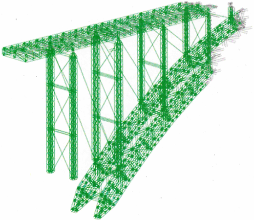
Here, one may assume a form-fitting connection between the framework and the concrete. The cross-section safety verification is done separately from the static model, with various assumptions regarding the interaction of the various materials.
The static models are used to calculate all construction states and the final state. Apart from the load effects, creep and shrinkage of concrete and temperature actions were investigated in the model.
The structural reassessment and reanalysis guidelines provide the possibility to determine the load model, depending on the actual traffic volume of the structure within the infrastructural network. Taking the traffic load parameters into account, the target load level was set at BK 60, which corresponds to the level prescribed in DIN 1072:1967 (DIN, 1967).
The loads are higher than those defined in 1928. From the comparative investigations, it is obvious that the standardised loads had increased. The respective values have been underlined in Table 2. Specifically for the bridge deck, compared to the other members such as the arches, the higher loads of SLW 60 (DIN 1072:1967) are much more critical. Unlike DIN 1072:1967, DIN 1072:1925 (DIN, 1925) also has no dynamic coefficient. In the original calculation for the Echelsbacher Bridge, an impact factor of 10% was assumed.
Comparison of traffic load models in different standards
| Bridge classification | DIN 1072: 1925 | DIN 1072:1967 | ||
|---|---|---|---|---|
| I | 60 | |||
| HS | NS | HS | NS | |
| Single vehicle: kN | 225 | 88·2 | 600 | — |
| Area load: kN/m2 | 3·9 | 3·9 | 5·0 | 2·5 |
| Maximum axel load: kN | 127·5 | 200 | ||
Brake loads for road vehicles are not defined in DIN 1072:1925. Therefore, there is no respective consideration in the original static to take the longitudinal reaction force into account.
The relevance of the traffic influence on the stability of the structure is reduced from the roadway deck, down to the arches and the foundations. According to the model, even without the consideration of damages, the roadway construction is unsafe. The arches, however, are capable of supporting today’s traffic load, even when the roadway deck is maintained with its current width.
The steel framework bears the greatest part of the self-weight of the system. Creep and shrinkage mean that the internal stresses within the steel framework are actually greater than that at the time of the completion the arch. Local damage to the steel framework can be compensated by concrete, if there are no relevant faults in the cross-section. However, due to the relation between steel corrosion and concrete spalling, these usually occur in the same section a structure.
The current state of the bridge and the result of the calculations prove that safety measures are required regarding the future handling and use of the bridge. It was shown that the life expectancy of the structure, without any interventions, is very limited. Several strategies for improvement of the bridge were developed and compared; these differ mainly in the extent of the actions to be taken. Considering all facts, the decision was taken to build a new bridge.
7 The new bridge
With its clear structure and design free of any ornaments, the Echelsbacher Bridge is undoubtedly special, not only in its natural and environmental importance, but also as a national heritage dating back to 1929. The bridge shows how important technical and engineering considerations played a major role in the deliberations of the era. The bridge’s special role in the engineering tradition and heritage, just as in 1929, and the technical requirements due to its infrastructural importance must not be ignored or neglected. This is the basis for the very special requirements on the replacement structure.
Structures influence nature and the environment, as well as the landscape, which is so well demonstrated by the historical case of the existing Echelsbacher Bridge. Over the years and decades of usage, the structure has become part of the natural environment and landscape and has even become a natural habitat for bats, thereby worthy of public protection. The existing bridge is not only included in the state’s list of protected structures worthy of preservation, but it is also a European protected habitat for bats.
The question now is how this structure, intensely in need of repairs, can be made fit for the future. The Bavarian Street and Roads Administration had explicitly decided on the formulations of the specifications for a planning dialogue, well before the awarding the competition and the realisation of a new bridge.
This way, at an early stage, the essential requirements of all the stakeholders and the public interest could be taken into consideration. This procedure is often successful in cases such as the Echelsbacher Bridge, with respective difficult and complex circumstances and conditions. This competition process increases public acceptance of the result and accelerates the subsequent planning procedures.
The planning dialogue resulted in two major prerequisites.
For the purpose of the construction activities on the Echelsbacher Bridge, it is essential that, first of all, an auxiliary bridge is constructed.
The two arches, part of the national engineering monument, must be preserved as a minimum and integrated and incorporated into the new bridge, albeit not necessarily as supporting elements.
Because of the extremely high environmental and technical requirements, this interdisciplinary competition was opened to civil engineers and architects, as well as landscape designers.
In April 2014, the competition was published in the official EU Gazette, with the request that joint planning associations had to be pre-qualified for the project. Seven teams were selected for further work, with a timeframe of 13 weeks, during which the pre-planning for the object and structure planning were carried out. The scope of the documentation to be submitted was clearly defined. After the respective submissions, all work was inspected thoroughly and assessed based on the following criteria: static and structural concept, architectural design, technical feasibility, construction processes, influence and effects on traffic, impacts on natural environment and landscape, consideration of heritage and monumental aspects, usage of space for construction site logistics and cost regarding production and maintenance.
On 13 December 2014, the competition jury announced the results. Many high-quality designs were submitted, but due to the special requirements of the completion, only two competitors were selected.
The winners of the first prize were Dr Schütz Ingenieuere, Kolb Ripke Architekten and Narr Rist Türk Landschaftsarchitekten. This team of designers excelled with the innovative idea of incorporating the arches of the old bridge in a comprehensive concept and integrating them in an environmentally friendly manner (Figure 10).
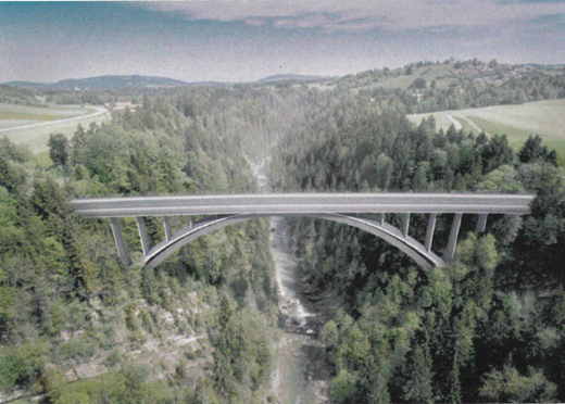
The new Echelsbacher Bridge (Dr Schütz Ingenieuere, Kolb Ripke Architekten, Narr Rist Türk Landschaftsarchitekten)
The new Echelsbacher Bridge (Dr Schütz Ingenieuere, Kolb Ripke Architekten, Narr Rist Türk Landschaftsarchitekten)
In a very delicate way, the new arch will span over the two existing arches, not only highlighting but also protecting the older two against inclement weather by its coverage. What is most impressive is the symbiosis between the old and the new and the fact that the old arches are part of the supporting structure and remain a functional feature during the construction of the new bridge.
8 Conclusion
At the time of its construction, the design of the Echelbacher Bridge was at the forefront of the technical advancement of its era. The Melan–Spangenberg construction technique had helped both the design and construction of the light 100 m long bridge across the deep Alpine valley, becoming part of the landscape. Over its service life, damages due to de-icing salts and environmental influences had made the bridge unsafe. After a thorough consideration of all options, it was decided to replace the bridge. The new design integrates the monumental arches in a comprehensive manner, preserving the basic concept of the Melan–Spangenberg construction technique for construction and re-invigorating the method after more than 80 years.