B. Jones, University of Southampton
The surface settlement points were between 11·09 m and 12·47 m above the frontshunt tunnel axis level during construction, not 14·8 m as stated by the authors. Above the tunnel centreline, the settlement points varied from 11·26 m above the tunnel axis level at Array 1 to 12·31 m above the tunnel axis level at Array 6. About a year after frontshunt construction ceased, the ground was made up to a level of approximately 14·8 m above the tunnel axis level, and this is probably where this number came from. The analysis presented therefore overestimates the depth of the tunnel by more than 2 m at least, and in some areas by almost 4 m.
The overall advance rate during construction of the frontshunt tunnel was 1·4 m/day, but while crossing the so-called ‘2D zone’ marked in Fig. 3 it was 1·7 m/day. If a weekend break in the middle of this zone at a chainage of 30·3 m were ignored, the average advance rate would have been 2·5 m/day across this zone.
In Section 4·1, paragraph 3, the authors state: ‘…there is a 0·5 m overhang left from the previous cycle initially supported with 75 mm of shotcrete that must be broken out.’ The purpose of the overlap was to stagger the joints of the initial layer and primary lining and thereby improve durability and water resistance. Breaking out of the overlap of the initial layer was of course not done on site.
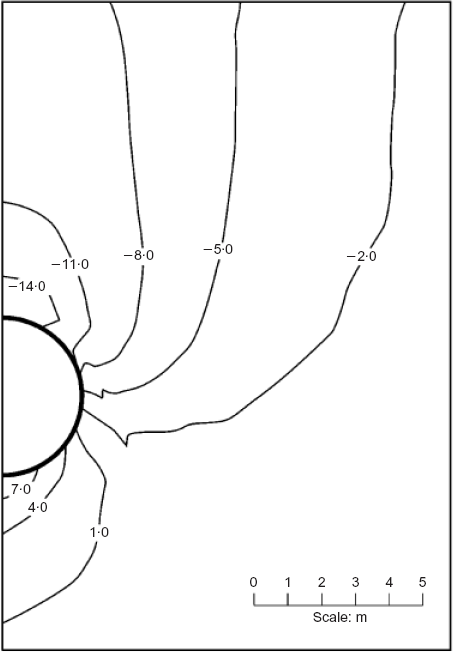
Figures 10 and 11, which show the ground displacements from the numerical modelling at the surface and in the ground, cannot be reconciled. Although the contours and vectors in Fig. 11 do not extend to the surface, scaling off the figure shows that the upper limit of the contours and vectors is at 13·3 m above the tunnel axis, that is, 1·5 m below the ground surface in the model. It is difficult to see how the computed settlement above the centreline at 1·5 m depth can be 25 mm in Fig. 11, while Fig. 10 shows that the computed settlement at the surface was only 9·5 mm.
Section 4.3 states: ‘The use of SCL to provide a rapid “stiff” support, minimising ground movements, would be in accordance with SCL design philosophy, where the lining is designed to accommodate high loads while minimising displacements.’29 But the ICE design and practice guide cited by the authors does not say that linings will have to accommodate higher loads if displacements are minimised. The balance of evidence from field measurements of stresses in tunnel linings in London Clay suggests the opposite is true.31 On page 27, under the heading ‘Concepts for design’, the design and practice guide says: ‘Maintain the strength of the ground as far as possible by preventing loosening and deterioration with the use of sprayed concrete applied as part of the excavation cycle.’
The subsequent paragraph of the paper states: ‘However, at fast tunnelling rates higher volume losses may occur, as the lining has less stiffness to prevent greater distortion prior to the next excavation cycle. This would accord with NATM design principles, where lining loads are minimised while permitting higher displacements in order to mobilise the “self-supporting” capacity of the ground.’30 Fig. 12 does not support this statement. It shows a trend of decreasing volume loss with increasing excavation cycle time. It does not show that decreasing excavation cycle time (or increasing advance rate) results in lower lining loads. Nor does it show that increasing volume loss results in lower lining loads. Therefore it does not accord with the ‘NATM design principle’ as the authors have defined it.
Rabcewicz's description of NATM in the series of papers cited30 does not say that higher displacements should be permitted in order to mobilise the self-supporting capacity of the ground. He emphasises the importance of installing the sprayed concrete lining and closing the ring as early as possible to prevent the development of loosening pressures. This could be called ‘preservation’, as opposed to ‘mobilisation’ of the ground arch, as discussed by Rokahr.32 Only in later papers does Rabcewicz briefly discuss the optimum level of deformation at which to install the lining, but cautions that the point at which loosening begins to occur must be known, and that a conservative approach must betaken with the lining installed before the optimal point is reached.33 The authors would have been more correct to quote the ICE design and practice guide's definition of the NATM philosophy in rock in this case.29
The authors appear to assume that neither the point at which the ground arch is fully mobilised nor the point at which loosening begins to occur has yet been reached in the case study presented, and that further deformation will result in further reductions in the load acting on the lining. It is worth stating again that there is no direct evidence from tunnels built in London Clay to support this view.
In a state-of-the-art report on ‘Deep excavations and tunnelling in soft ground’ to the 7th International Conference on Soil Mechanics and Foundation Engineering in 1969 Peck said:
Long experience has demonstrated that, except possibly in certain swelling clays, no tunneling method has yet been developed in which the strains and deformations are so small that the strength of the soil is not largely mobilized. Therefore, it is quite properly considered good practice to keep the deformations as small as possible, in order to hold the avoidable loss of ground and consequent settlement to a minimum and to prevent deterioration of the soil due to excessive local distortions or remolding.
So the level of deformation required to mobilise the ground arch in soft ground was so small that it had never been found. In fact, SCL tunnels in London Clay, which tend to have smaller values of volume loss than the segmentally lined tunnels of Peck's experience, also tend to experience lower values of radial stress that show little propensity to increase in the long term.31 Therefore the concept of allowing a prescribed amount of deformation to occur is not applicable to soft ground open face tunnelling. In fact, Peck said that allowing deformation to occur would only result in loosening and deterioration of the soil mass, and recommended keeping deformations as small as possible. To use the parlance of the NATM philosophy, this suggests that mobilisation will occur regardless, so preservation of the ability of the soil to support itself takes precedence in soft ground; soft ground open-face tunnels have entered the ‘loosening’ part of the ground-reaction curve before the support can be introduced.
One of the conclusions of the paper is that more accurate estimates of volume loss may be obtained by 3D FE modelling than by empirical prediction. Presumably then, what the authors refer to as a ‘back-analysis of an SCL tunnel’ was performed as though it were really a prediction during the design phase. If not, then a comparison of an empirical prediction with a back-analysis would be unreasonable. In a true back-analysis, either the parameters or the model itself are deliberately adjusted to achieve a better fit to the observations.34
Authors’ reply
The intent of the paper was to report on our 3D analytical work to examine the possibility of estimating, in a realistic way, the development of settlement around an SCL-supported tunnel heading. The paper was not intended to be used as a settlement case history, nor was it an investigation into the development of loads and distortions of the lining. On that basis we chose a relatively simple model of the behaviour of the SCL lining.
The discusser notes that we have stated that the depth to tunnel axis is 14·8 m. This is a typographical error, and we apologise for not correcting this in the final proofs. It will be clear from a closer reading of the paper that, from the C/D ratio and depth of gravel quoted, the depth of the axis of the tunnel as modelled was approximately 11·8 m (see also Fig. 3).
Our overall assumed rate of advance of 1·3 m/day (18·5 h cycle per m advance; Fig. 12) is confirmed by the discusser's estimate of 1·4 m/day. For our analysis we assumed that a 1·5 m/day advance rate was typically completed in a single one-day shift (i.e. a 16 h cycle in Fig. 12) within the 2D zone, for which we estimated a volume loss of around 0·8% from the monitoring data. However, the incremental advance rates elsewhere along the drive varied widely. Thus the discusser's estimate of 1·7 m/day within the ‘2D zone’ (i.e. a 14 h cycle) is generally in accord with our assumptions. Our analysis was of course specifically aimed at examining the sensitivity to variations in the rate of advance.
Regarding the 0·5 m overhang of the initial 75 mm shotcrete layer, this is a significant issue when assessing an appropriate P/D ratio. Information presented by the contractor which built the tunnel (BTS presentation, February 2003) indicated that the excavation of each 1·5 m advance required breaking out of the initial 75 mm SCL applied to the face and crown ahead of the final 250 mm layer of shotcrete. As shown in that presentation, at the point of breaking out little of the 75 mm initial SCL remained in the crown. We believe that this would be a reasonable representation of the actual conditions at the tunnel face.
Figure 11 provides incorrect information, and we apologise for including an incorrect version of the figure. The correct plot from the actual data file analysed is included with this reply. Our numerical model assumed 11·8m from ground surface to tunnel axis level and the calculated settlement is in agreement with Fig. 10.
With regard to our comments on SCL versus NATM design philosophy, we accept that it was perhaps unwise to introduce this in our discussion as our analysis was not concerned with lining loads. The key point we wished to raise was that, by modelling different advance rates for a given tunnelling sequence and rates of hardening of the SCL, we were able to show that, contrary to common belief, increasing the rate of advance with an SCL tunnel may not necessarily result in a reduction in ground movement; in fact, the opposite could result.
Our conclusions regarding empirical versus numerical methods of estimating ground movements were based on an objective application of 3D modelling techniques and a tried-and-tested non-linear, anisotropic soil constitutive model. We of course benefited from knowledge of the actual tunnelling method employed, the time–stiffness properties of the SCL and our knowledge of the ground conditions. Our concluding remark was simply to say that, as we now move into tunnelling methods (such as SCL) for which there are few reliable empirical data yet available, the role of 3D numerical modelling may, when applied under the right circumstances, provide a more reliable approach to the estimation of induced ground movements than traditional empirical methods.