In their paper24 the authors investigated the Surtees Bridge, founded on soft soils, which had been showing indications of distress due to lateral movements related to the unforeseen settlements of the approach embankment. Some estimates were made, based on simple empirical3 approaches; however, the results were not able to explain the lateral movements observed for pier E and abutment F in a satisfactory manner. In this discussion, the method proposed by Springman25 is used to recalculate the lateral pile deflections.
The case reported in the paper is a soil–pile interaction problem, and is influenced mainly by the high compressibility and time-dependent behaviour of clay layers, the interaction between the abutments, piles and piers, variable vertical loading conditions in the transverse direction due to pre-existing Victorian fill, and the existence of another bridge in the vicinity. To comprehend the interaction and the effect of individual factors on the piles and piers, a detailed numerical analysis is necessary.
However, to understand the mechanism between the soil and the Surtees Bridge, in the broad sense, deformations of piers and abutments relative to the deck, and the indications of distress points on the bridge deck, must be appraised. Two indications have been cited to form the basis of the lateral deformation calculations: (a) horizontal movement of the sliding bearings of abutment A (10–15 cm westward); and (b) greater westward movement of the head of pier E than of the bridge deck or abutment F.
According to the first indication, unless the bridge deck buckles, the amount of horizontal movement at abutment A and abutment F has to be similar. However, there is a remarkable difference with the authors' simple empirical3 estimation and the movements observed. The calculated horizontal pile displacements are 34 cm for pier E and 30 cm for abutment F (originally 40 cm, but empirically reduced by 25% to reflect the stiffer pile group with raked piles by the authors). A further analysis could be done using the method proposed by Springman,25 in which the horizontal passive pressure acting on a pile in a group, pm, can be defined as
where h is the depth of the soft soil layer, q is the embankment surcharge, d and s are the pile diameter and spacing respectively, F is a parabolic function (= 2·0), G is the shear modulus of the soft soil layer, and EpIp is the bending rigidity of the pile. These pressures are then used with the SIMPLE methodology to calculate the maximum moments and pile deflections. Pier E is modelled with four piles, as a free-headed pile group, in the analysis, whereas abutment F is modelled as a pile group with a rigid cap.
The following assumptions are made to achieve an approximate analysis within the scope of this discussion, and to simplify the complex interaction between embankment, soft soil, pile and pier.
The effect of vertical embankment load is arbitrarily reduced to 50% for pier E, representing the overburden.
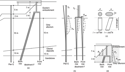
The loaded length of the pile in the 16–18 m deep soft soil layer is about 60% of the soft soil thickness (Figure 10(a)).
The s/d ratio for pier E is assumed to be about 4·0.
The piles under the abutment are assumed to be in three rows, with each having 17 vertical piles (s/d ≈ 4·0).
Two rows of raking piles are represented as a single row of vertical piles (Figure 10(b)).
To take the effect of 1H:3V raking for the back row of piles into account in the calculations, the pile section that is resisting the lateral movements along the horizontal plane is considered as an ellipse instead of being circular. The dimensions of the ellipse are 0·60 m and 0·30 m, as seen in Figure 10(c).
The pressure acting at the top of the soft soil is taken as half of the maximum pressure acting on the pile (p0 = p m × 0·50).
The SIMPLE methodology assumes that the piles are loaded by the passive thrust of soft soil moving past the piles and the stiffer soil resisting these lateral loads, as in the PIGLET approach.26 For this reason, only the pile length embedded under the embankment layer is considered. Although this consideration is adequate to define the loading conditions of pier E, further estimates are necessary to explain the loading conditions in the embankment layer, for abutment F. The classic active–passive lateral loading is assumed to be acting on the retaining wall, as given in Figure 10(d). The internal friction angle of the embankment is calculated as 35° from the standard penetration test (SPT) values. For a rough vertical wall retaining the embankment, the active earth pressure coefficient is taken as 0·25 and the passive earth pressure is taken as 1·25 (typical values change from 1·1 to 1·65 for a smooth to rough wall), considering the inclined surface of the slope shown to the left of the abutment (Figure 10(d)). The active pressures on the retaining wall, Pa, and on the piles, Pa,pile, are calculated separately, and the net lateral load Pnet applied on the pile cap is calculated as 100 kN. The passive thrust pm obtained from Equation 3 and the results of the SIMPLE analysis for pier E and abutment F are given in Table 7. The lateral deflections are calculated as 16·1 cm for pier E and 13·9 cm for abutment F, which is consistent with the observed movements.
Although the analysis carried out in this discussion also relies on some empiricism, it is believed that critical components of the governing mechanism are taken into account, including: the soft soil layer thickness; the interaction of the pile and the soft soil; and the pile spacing, geometry, boundary conditions, and material properties. Hence it is possible to make a more realistic estimate. The parameters that affected the SIMPLE calculations for the Surtees Bridge case are: the embankment pressure q; the loaded soft soil layer thickness H; the Ip values (especially for the back pile row); and the net pressure acting on the pile cap, Pnet. The calculated pile bending moments for pier E and abutment F from the SIMPLE analysis also indicate that very probably the pile bending moment capacities will be exceeded.
It is worth noting that the long-term vertical settlement at the abutment (chainage 4760) was Δs = 71 cm. If this is compared with the empirical relationship proposed by Tavenas and Leroueil,28
where Δym is the maximum lateral movement beneath an abutment without piles, it suggests a free lateral soil movement of 10–13 cm, which is slightly below the values calculated for the piles alone.
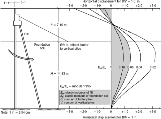
Regarding the latest interesting observation by the authors, confirming rotation of the western bank seat away from the river, the numerical parametric study described by Siriwardane et al.29 provides a good opportunity to estimate the degree of backward rotation and link it to a more deeply seated mechanism caused by consolidation in the soft layer. Siriwardane et al.29 concluded that ‘most perched abutments founded on end bearing piles driven through approach embankments underlain by soft compressible foundation soils tend to rotate and move backward away from the bridge superstructure’. A typical result from their work is given in Figure 11, conveniently showing that the geometric conditions assumed by them approximately represent those of the western embankment and its underlying soil. Using the values of undrained shear strengths of the Victorian fill and grey alluvium given in Table 3, the modular ratio of the stiffnesses of soft soil divided by that of the western embankment could be estimated as an upper bound (e.g. 38·0/98·0 = 0·38), if we assume that the degree of strain mobilisation was similar in each soil. Considering the sand and gravel content of the fill material, it could be postulated that the values of the elastic modulus of the fill would be relatively greater owing to lower shear strains. Hencethe discussers estimate that the modular ratio values for the western embankment may well reduce by up to factor of 5, represented by the shaded zones in Figure 11. These indicate a maximum horizontal displacemen of 0·9 in (2·9 cm) and a backward (anticlockwise) rotation of just under 1°. These values are consistent with the authors' findings about the angular rotation of the bank seat.
Authors' reply
The authors would like to thank the discussers for their interesting and informative addition to the paper. They would like to take this opportunity to present one further piece of information regarding Surtees Bridge that has recently come to light. Widening of the A66(T) River Tees crossing necessitated demolition of Surtees Bridge, which was undertaken in two stages. The first involved removing the southern running lanes, together with the associated southern sections of the bridge piers and abutments, while leaving the northern running lanes in place and operational. Subsequently, when part of the new bridge was available for traffic, the remainder of Surtees Bridge was demolished.
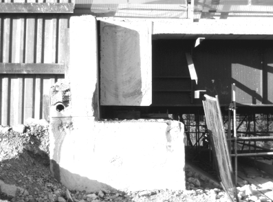
When the southern section of the western abutment (abutment A) was cut away in the first stage of demolition, it allowed direct observation of a cross-section through that abutment. This was a piled bank seat set upon the western approach embankment to support the bridge deck through a sliding bearing. Observation revealed that what would originally have been vertical surfaces were inclined slightly towards the west (see Figure 12), and the expansion gap between the abutment and the deck support beam narrows with depth. These observations indicate rotation of the bank seat.
There have been no serious performance issues associated with the western approach embankment over the lifespan of Surtees Bridge (unlike the eastern approach embankment that was the primary focus of our paper): thus a deep-seated rotational failure of the approach embankment can be dismissed as the cause of the observed abutment movement. It is therefore deduced that the bank seat has been displaced away from the river by movement of the bridge deck. The variation in the expansion joint gap with depth indicates that the angular rotation of the bank seat is around 1·25°. Thus, if the rotation occurred about the base of the bank seat, the westward displacement of the contact point with the bridge deck would be around 25 mm. However, if the effective point of rotation was lower because of the constraint of the piled foundations, the westward displacement of the point of contact would be higher. Without knowing the detailed mechanism of abutment rotation it is best concluded that the initial estimate of 100–150 mm westward displacement of the bridge deck due to movement of the eastern abutment (abutment F) is most probably an underestimate.
In the original paper a very simple empirical method was used to evaluate whether movements of the magnitude experienced by pier E and abutment F could have resulted from deformation of the alluvium under loading from the eastern approach embankment. Taking such an approach necessitated ignoring variations in the ground profile close to the river. In the immediate vicinity of the river channel the grey alluvium consists of an 8 m thick upper layer of silt/clay over silty fine alluvial sand (see Figure 5). While the significant thickness of coarser alluvium is present only very close to the river (it rapidly becomes clayey silt/silty clay towards the east, a factor not sufficiently recognised pre-construction), it could potentially have affected the behaviour of pier E. We applaud the more sophisticated approach taken by the discussers to calculate the movements of pier E and abutment F, but note that they have made the same simplifying assumption about the ground condition near pier E.