

An essay on the foremost British government soil mechanics laboratory from earlies times to 1957.
3. PART 3: 1944–1948
3.1. The Soil Mechanics Section after 1944
Smoking was the norm, getting to and from the lab was by bus or bike, and men were called by their surnames. A year after I joined the Section came Marsland from serving in the Army in Burma, Chaplin from Cambridge and Smith, fresh from Queen Mary College to be, as he told me, the youngest Scientific Officer. In 1946 the 30-year-old Meyerhof came from Ove Arup: he had been educated at University College, where he had read structures, but had also been taught soil mechanics by Capper. From college he had gone with Harry Stanger in his civil engineering testing laboratory, and had tested the concrete for Mulberry Harbour. From Stanger, he had gone with Ove Arup as a structural engineer.
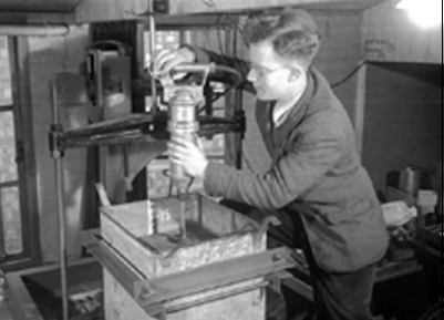
Soon our staff was increased further by Swainson and Loudon. Chaplin became Meyerhof's slave and carried out numerous model footing tests in tanks of dry sand. These were set up in the plywood hut, using the loading frames, and the noise of Chaplin compacting the sand with a Kango hammer used to drive us all out of the hut (Fig. 1). Yet Chaplin could hear perfect pitch, and could set up a vibrating wire gauge in one of Ward's tunnels to almost exactly the required frequency without a reference set. During the next few years we were joined by Thomas, Cheney and Burford.
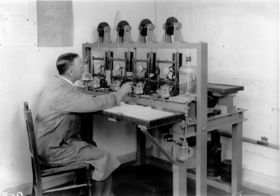
In August 1944, the apparatus in the lab consisted of three strain-controlled, hand-driven 6 cm square shear boxes; two 1½ in. triaxial cells in hand-driven loading frames; a frame of four lever loaded oedometers (Fig. 2); sieves, pipettes and vacuum pump for particle size analyses; an accurate (to 0·1 gm) balance, numbered glass bottles and an oven set at 105°C for water content determination. There was a delightful routine. In the morning, our lab boy, Brownie, would take all the bottles out of the oven and put them in a desiccator to cool, while he read the newspaper. Then he would weigh all the bottles, entering the values in the ‘weight book’. Young Bond, Brownie's assistant, would then work out the water content as a percentage, using a Brunsviga cylindrical calculator. This had nail-splitting little brass tags sticking out of the cylinder, and you clicked these round to form the number. You could then multiply by turning the chrome handle (and cylinder) one way, and divide by turning it the other. When you had turned enough, it would ring a bell, and you then turned it back one turn, and moved along to the next number. The cheerful ‘dings’ of this machine, as Bond calculated the water content to three places of decimals, was one of the joyous morning noises of the lab. One of Brownie's other important functions was to play ‘shove ha'penny’ with Cooling at lunch-time. They had a lovely slate board, 24 in. long and 15 in. wide, marked off with parallel lines to form nine beds each 1¼ in. apart—just wider than the 1 in. diameter of a halfpenny coin. Three coins were used and the object of the game was to slide each coin from the outeredge of the horizontal board by a tap from the palm of the hand, to stop between a pair of lines. A successful positioning was recorded by a chalk mark on one side of the board for one player, and on the other side by the other player. The winner was the one who got three coins into each of the rows first. In those days, we had copper coins of ¼d, ½d and 1d: there were 240d to the £1. The coin used for the game was the ½d.
3.2. Field work
For field work in 1944 we had a ‘coffin’ containing a portable unconfined compression apparatus, with a supply of its paper charts, and a celluloid mask; several snap-capped glass jars; several 3 ft (0·9 m) lengths of ¾ in. (19 mm) bore steel pipe rods with a 5 in. (127 mm) auger; plus a Tee piece and wooden handle; several brass sampling tubes for 1½ in. (38 mm) samples with an adaptor to connect them to the boring rods and steel tommy-bars that fitted holes in the rods for screwing them together. Two pairs of the boring rods fitted into brackets on the sides of the box, so that two men could carry it like a stretcher. There were three vans on the station: a six-cylinder Dodge, a Ford ten and a Morris that had been a WVS tea van. The Dodge was the van to have, but most often we had to manage with the Ford or the Morris. We used to take the ‘coffin’ to a site, hand-bore holes, taking ‘undisturbed’ samples in the 1½ in. tubes, then test them in the UCA, and put them in a glass bottle. Back in the lab we would take smaller samples from the jars for water content and store the rest of the samples on shelving under the job location number.
One of the first jobs I was engaged on was an investigation of the failure of a flood bank on Borth bog, in Wales, under W. H. Ward. The distance was great enough to ensure the Dodge—I loved driving—and we took lightweight 6 in. (152 mm) diameter stove pipe to use as borehole lining. I took rope and a pulley block, and with the use of a long pole to form a lifting rig, I bored down 40 ft (12 m) to the bottom of the bog, to sample the underlying strata. Cooling with his family took a holiday cottage on the sea front at Borth so that he could both visit the job and enjoy golf on the famous Borth course.
Another early job was an investigation of a rotational slip from the side of a cutting on to the main London to Edinburgh railway line just south of Grantham station. It was a slow-moving slip in the Lias clay and a trainload of clay was being taken away from the toe every weekend to keep the main east coast line open. We put several hand borings into the very stiff clay, taking and testing samples. We found the slip surface in some holes, and drove in slip indicators, consisting of short lengths of steel tube on a central mandrel that was withdrawn after driving. After some time, letting down the mandrel again could identify where movement had occurred. The failure was analysed by slip circles, using the measured strengths. It was necessary in the φ = 0 analysis to find the centre of gravity of the section enclosed by the trial circle. This we used to do by drawing the section on cardboard and cutting out the enclosed part, then hanging it freely at two points from a pin stuck into a vertical line we had drawn on the wall. The vertical line was transferred to the card: the centre of gravity shown by the point where the lines crossed. Six to nine circles were tried, and a little plot made of the factor of safety values. From this the position for the most dangerous circle could be found.
Liverpool abattoir had basement cold rooms. During the war, their temperature had been lowered so that frozen meat could be kept. The steel-framed building above ground level had rail tracks fastened to the undersides of steel beams to carry wheeled hooks on which carcasses were suspended for transport about the market. It was found to be hard work pushing carcasses towards the middle of the building, but there was a danger that they would run away when moved towards the outer parts. The centre was found to have risen by 15 in. (0·38 m). We suspected frost heave, and hand-bored holes through holes cut out of the concrete floors of the cold stores, taking 1½ in. (38 mm) samples continuously until we had passed through the frozen ground, finding quite thick bits of the ice lenses contained within the lengths of the tube samples. We made up columns of thermocouples, which we lowered into the bored holes, and backfilled them with warm slurry made from the removed frozen silty soil. Our instructions to the owners were to raise the temperature by only 2°C and wait until the zero isotherm retreated to a steady position before the next temperature increase, so as not to suddenly thaw the ice lenses, which would have drastically reduced the bearing capacity of the silt and caused foundation failure. As a permanent remedial measure, we designed electrical heating pads to be placed under the thick floor insulation, controlled by a thermostat that would turn them on if the temperature of the soil just below the insulation should fall to zero.
3.3. Shallow foundations and trees
Government found that bomb damage claims were coming from areas remote from the known positions of bomb strikes. BRS was asked to look into this and we found that damaged houses were on clay soil, had shallow foundations and/or had trees growing nearby. A common situation was with lines of semi-detached houses, whose owners had planted rows of poplar trees on the boundary between adjacent pairs, to screen them from their neighbours. Our investigation at many damaged houses, using the ‘coffin’ gear, soon led us to a simple rule of thumb that single trees should be kept at a distance of at least their mature height, and rows of trees 1½ times their mature height from houses on clay soils. Shrinkage of the clay away from the foundations left brick walls in a state of tension. A slight ground shock, such as from a distant bomb, could cause sudden failure, showing that claims were justified. Continuing our research, we installed plate settlement gauges to measure the vertical movements at various depths in clay below grass and stripped ground during a year's seasonal changes, and found that foundations should be at least a metre deep to avoid seasonal movement with only grass. With shrubs or trees, the depths must be much greater in clay soils. A solution was the short bored pile foundation, and large numbers of post-war new houses were put on these foundations. Discussions during the Building Research Congress, held in London in 1951, emphasised worldwide interest in the problems of houses on clay soils.
Some 30 years later, insurance companies generously added cover against subsidence to household policies at no extra premium, because there were hardly any cases of serious damage caused by sink holes, or mining subsidence that could not be claimed from the mine responsible. But the effect was devastating. Building societies require a survey to be made of a house prior to purchase, and a typical situation would arise where a surveyor would find some cracks in a house and would suggest that they were caused by foundation movements, so the house should be underpinned before he could recommmend completion of the sale. The sellers would be extremely upset, imagining the cost of underpinning, but the surveyor would tell them not to worry, because the damage was due to subsidence that would be covered by their house insurance. In this way very many houses were underpinned needlessly, and new firms sprang up to do underpinning, often with short bored or mini-piles, driven or bored. As the cost escalated, the insurance companies came to BRS to see if we could find out why the earth was suddenly opening up all around. Having, as we thought, solved the problem in the late 1940s, we had to issue new digests and papers giving a scale of damage, pointing out that millimetre-wide plaster cracks are often caused by thermal and humidity changes within the structure of a house and are not caused by foundation movements. Much more direct evidence of foundation movements is required before underpinning should be considered, and even then, underpinning a part of a house can cause further damage by relative movement between the now fixed underpinned part and the rest.
3.4. Vibrating wires
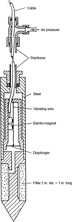
The Engineering Division used a variety of strain gauges, including vibrating wire gauges, following closely the designs of Maihak of Hamburg. Paper-mounted, stuck on, resistance strain gauges, were very poor in the field because of the serious effect of damp and because they had to be calibrated together with their connecting cables. If these became damaged in the field, they could not be repaired or reconnected without completely upsetting the original zero readings. The vibrating wire strain gauges were immune to both these troubles. Shortly after I arrived in 1944, Jerrard sought my help to calibrate a vibrating wire piezometer. It had been made by workshops as a copy of a piezometer that Cooling had seen described in Engineering News Record. According to Goodman,1 this remote reading piezometer was probably the first in soil mechanics history. It had been designed by Terzaghi with the help of Roy Carlson in 1942 to measure pore pressures in the harbour clay under the sunk Normandie ocean liner, in order to control the rate of raising to avoid hull damange. In the BRS copy, the Carlson unbonded resistance strain gauge had been replaced by the vibrating wire to give the advantages mentioned above. It was as roughly sketched in Fig. 3. The long steel nose was about 50 mm diameter, with a pointed porous stone, machined from a piece of natural stone and sealed into the end of the steel tube with gasket cement. Pressure was meausred with a large thin copper diaphragm of about 75 mm diameter and 0·5 mm thick. A 150 mm long vibrating wire was attached to the centre of the diaphragm, and activated by electromagnets (as used in telephone ear pieces), placed at its mid-length. We used a Maihak master control vibrating wire that was maintained; stretched by a micrometer screw pulling on a spring. Earphones enabled the operator to listen to both vibrating wires at the same time, and the micrometer screw was adjusted until both wires had the same frequency. This was achieved by reducing the frequency of the out-of-balance wow-wow to zero. There was a 10 m deep borehole near the lab, full of water, and Jerrard's plan was to lower the piezometer into the water and take readings every 5 ft (1·524 m). Held above the water, the zero reading was fine, but as the first 5 ft depth, no reading could be obtained. We thought water had got in, and stripped the piezometer to find the wire quite dry, so I had another go, and found that the readings changed rapidly as the intrument was lowered inches, much less 5 ft! Using Temoshenco's theory for thick diaphragms (we had his book in the lab), I worked out that the diaphragm should have dimensions more like a halfpenny than the very flexible copper diaphragm that was in the peizometer, if it was to measure pressures approaching 10 m head of water. Accordingly, I made working drawings for the piezometer, shown in Fig. 4. It had a ventilated casing so that the back of the diaphragm was at a known pressure (normally atmospheric) to avoid errors that could be caused by any change of pressure within a sealed body. This feature also enabled calibration to be checked with the piezometer in situ. It worked very well, and was one of the piezometers I used to study response times.2 Unfortunately, it was never used in the field. It was too early in the Section's use of the vibrating wire gauge.

Rough sketch of the BRS vibrating wire piezometer copied from the Terzaghi/Carlson piezometer
Rough sketch of the BRS vibrating wire piezometer copied from the Terzaghi/Carlson piezometer
Five years later, vibrating wire load gauges used in a strutted excavation during 1949–1950 were described by Skempton and Ward:3
‘They consist of a steel tube about 5 inches [130 mm] long and 3 inches [76 mm] diameter with a wall thickness of about ⅜ inch [10 mm]; the load being carried axially on the tube. A pre-tensioned silver-plated piano wire is stretched between the centres of circular steel plates recessed within and anchored to each end of the tube. The gauge is calibrated directly for load in a testing machine against readings on a screw micrometer that is adjusted to stretch a similar vibrating reference wire to exactly the same frequency as the load gauge wire. The plot of load against micrometer reading is linear and almost free from hysteresis. The gauge was developed by the Engineering Division of the Building Research Station from a similar type of instrument manufactured by Messrs Maihak of Hamburg.’
These gauges were further improved within the Soils Section and they attracted the attention of the Norwegian Geotechnical Institute (NGI) who wished to measure strut loads in excavations in soft clay for their Oslo underground, and three of their engineers came to BRS to assist with the calibration of a batch of these gauges that had been made for them. This introduced the vibrating wire technique to NGI, where Elmo DiBiagio made very considerable developments leading to the large array of gauges produced by Geonor, the manufacturing branch of NGI.
Our other use of vibrating wire strain gauges was in the Underground (metro) tunnels. Cast iron linings were first used for the Tower Subway under the Thames in 1869, and their design was so satisfactory that they remained of the same section for very many years. The only cracking observed was when another tunnel was driven alongside. BRS first measured stresses in linings in 1942, using Demec gauges, when London Underground was constructing a new tunnel. In 1952 there came the opportunity to make measurements on two 25 ft (7·62 m) diameter tunnels at a depth of 100 ft (30·4 m). Theodore Chaplin designed a method for mounting the vibrating wire directly on to the cast iron lining. His system used steel gauge posts of in. (7·9 mm) diameter screwed into tapped holes in the lining, as indicated by Fig. 5. The posts were drilled 0·136 in. (3·5 mm) across a diameter to take the wire, and spaced 3 in. (76 mm) apart to produce the strain gauge. A strip of Tufnol put across the tops of the posts carried the electromagnet assembly and the whole gauge was covered by a stout cast iron cover bolted down on to a rubber gasket.
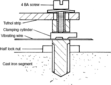
Anchoring the ends of the wire was by a 4 BA (about 4 mm) screw bearing down on an ⅛ in. diameter clamping cylinder to spread the gripping force on to the wire, as indicated by Fig. 5. With these gauges, where you could see what you were doing, it was possible to get the end of the clamping cylinder exactly flush with the edge of the hole, but with wires, such as those inside the load gauges, it was not so easy to get it right, so that the end of the clamping cylinder could be in the incorrect position shown by Fig. 5. This gave the wire two effective lengths on the two sides of its vibration, confusing the natural frequency of the wire and sometimes making it difficult to match. This snag was overcome by Tom Thomas who had the idea of, in effect, putting the wire through the middle of the clamping cylindrical steel end piece and swaging it on by forcing the cylinder through a die of slightly smaller diameter. He went to the workshops of our National Physical Laboratory (NPL), where they did some experimental swaging with short lengths of fine bore tube. Back at BRS he made up a few wires of the required length with swaged slugs, but did not reach a stage of production.
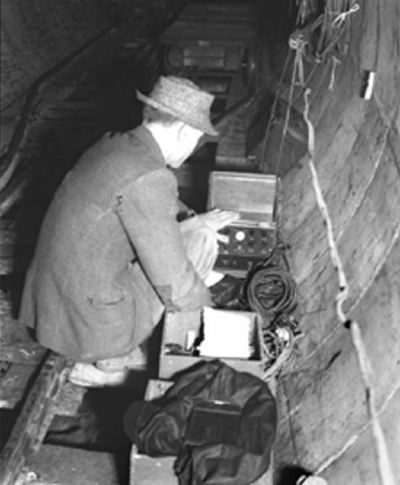
General dissatisfaction with the master gauge system caused thoughts to turn to some stable electronic method for producing frequencies against which gauge wires could be measured. Through various contacts, Chaplin went to the Radio Research Organisation at NPL where they found a circuit for a stable oscillator using thermionic valves. They made one up, with a cathode ray tube to show the produced oscillation and the gauge wire vibration. A d.c. surge was used to pluck the wire, and the apparatus, completed in 1952, was most successful. Chaplin4 went on to find that, by using the frequency to pluck the wire, he could bring weak gauges back to full operation. There were various slight difficulties with this prototype, such as insufficient screening, and valve heat affecting sensitive parts. Ward and Cheney,5 with help from many in the lab, designed and made three sets in compact cases suitable for field use. These had tuning forks for frequency reference and incorporated the Chaplin resonant plucking feature. Fig. 6 shows Dr Ward taking readings with one of these oscillators in a tube tunnel.
At NGI DiBiagio perfected the system for swaging on end pieces, an idea borrowed by I. Hawkes who used the system with his instrumentation firm in the USA. In turn, Soil Instruments bought wires with swaged end pieces from Irad Gage during the late 1970s until they began making their own. But this is going well outside the time limit for this essay of 1957, although it must be said that the success of the vast instrumentation of the gigantic North Sea oil platforms depended heavily on the vibrating wire sensor, and the developments made by Dr DiBiagio.
3.5. Visits to laboratories of other countries
In 1946 Ward went with Golder, Glossop and McLean of RRL on a mission to liberated Europe to find out what soil mechanics developments had taken place in the various countries during the war years. This extensive tour sowed the seeds for Géotechnique. Visits were made to Paris, Lausanne, Zurich, Delft, Ghent and Liége. The possibility of producing a soil mechanics journal was discussed with Daxelhofer at his home near Lausanne, and it was he who suggested the title of La Géotechnique. To enable the publication to be the journal of a learned society, the Geotechnical Society was formed by Glossop, Golder, Cooling, Skempton and Ward. This was a society of convenience, not to be confused with the Soil Mechanics Discussion Group that held meetings in the Institution of Civil Engineers, first in 1940, that became in 1947, the society of the British National Committee of the International Society for Soil Mechanics and Foundation Engineering–a title mercifully shortened to the British Geotechnical Society in 1964 when we incorporated the new international society for rock mechanics and became its national committee too. In all this the names of Cooling, Skempton, Golder and Wentworth-Shields were prominent and the influence of the soils group at BRS was evident. Details have been given by Cooling, Skempton, Glossop and Golder.6
Two results from the post-war tour of Europe were that Dr Leo Casagrande (Fig. 7) was brought from Germany to join the soils group at BRS and one of the big rütteldruckver pokers was shipped from Germany to BRS. Leo had developed electro-osmosis in Germany, and was well-known for his work in stabilising the very soft soil in Norway during construction of the German U-boat pens at Trondheim. We tried his system to stabilise some shallow slips in London clay slopes at Stanmore, and to consolidate soft fill in a main line railway embankment caused when a culvert had blocked and washed out. The system works best in silt, and these British soils did not seem to be suitable. Equally, vibro-flotation works best in loose sand, and we did not seem to be troubled with that, so the large rütteldruckver poker lay out in the woods rusting for many years until it was cleared away for scrap. It was into the 1950s before similar vibro-flotation pokers were brought from America by Cementation. Even then it was not much used and only after several more years did it become an accepted method for ground improvement in Britain.

In 1947, Cooling and Meyerhof went to North America on the same mission of renewing contacts and to find out what soil mechanics developments had taken place in Canada and the USA. The counterpart of DSIR in Canada was the National Research Council of Canada, established in 1916, which had also set up a Building Research Station in 1947 in Ottawa. Legget was the director, and when he heard of Cooling and Meyerhof's visit, he arranged a Conference on Soil Mechanics, and this has since become known as the 1st Annual Canadian Conference on SM&FE. Hughie Sutherland was studying at Harvard at the time and he attended the conference. A special Golden Jubilee Conference was arranged for 1997; both Professor Meyerhof, now living in Nova Scotia, and Professor Sutherland from Glasgow University, were among the six who had attended the 1st Conference, and were given special recognition as the ‘survivors’.
3.6. Triaxial apparatus
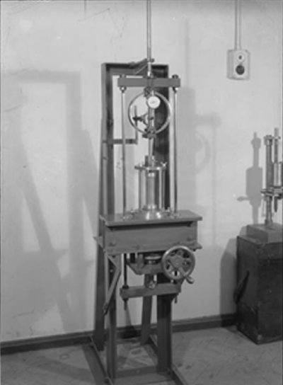
After the Jenkin era, the first triaxial machines, made by workshops (shown in Fig. 8), were based on the Harvard design by Casagrande to take samples 4 in. (102 mm) long and 1·5 in. (38 mm) in diameter. There must have beem some difficulty in buying rubber sheaths at that time, because one of the duties for Brownie was the making of sheaths. He had an array of tall glass cylinders full of rubber latex into which he dipped long glass test tubes of 1½ in. diameter, that were held by retort stands above the tall cylinders to drain and cure. Each sheath required about five dips, with drying in-between each and an overnight cure before being rolled off the test tube after dusting with French chalk. The rubber sheaths were attached to the end pieces in the triaxial cells with two flat Stationery Office elastic bands, compressed by a double turn of soft iron wire that was tensioned by twisting its ends together. It required a delicate touch with pliers to effect this successfully without upsetting the sample. I designed end pieces with clamping rings that were pulled up tight on to the sheath by a central screw, making a perfect seal. I went on to motorise the two machines, using fixed speed a.c. motors and a complex chain of gears that gave a wide range of rates of strain. The triaxial machines had not been much used: the UCA was much easier to use and gave its autographic result. But, following Chingford, we had agreed to help the MWB with the design of their next big reservoir, Walton (now named Queen Elizabeth II) in the Thames valley.
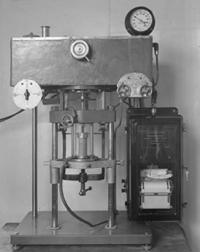
Just after the war, they began a site investigation of the foundation along the 4·36 km length of this encircling dam. U4 samples began arriving at BRS in large numbers to be tested by triaxial compression rather than by unconfined compression, to avoid premature failure on ‘slickensides’ that existed in the London clay samples. I was unable to cope with the numbers and Cooling told MWB that we needed help. They sent one of their fairly new members of staff, A. W. Bishop. He had already been working on the task and at Roseberry Avenue (MWB headquarters) had designed, with help from the Mechanical Section, an autographic triaxial apparatus. Axial load was applied hydraulically through a piston and rod that entered the cell; both kept rotating slowly to avoid frictional losses, enabling the axial load to be measured by a recording pressure gauge. The fixed speed of movement of the paper chart could be used as axial strain because the motor-driven oil pump advanced the piston at a constant rate. This monstrous waterworks piece of apparatus, shown by Fig. 9, had been made in one of the waterworks workshops. It was brought to BRS where we commissioned it and set about testing what turned out to be 471 samples, undrained at a cell pressure of 30 lb/in2 (207 kN/m2). The design of Walton has been described by Bishop.7 After that work, the machine was sent to the MWB new soils laboratory. The head of the Mechanical Section of MWB, who had helped Bishop with the mechanical details and supervised the machine's construction, patented the apparatus. It continued to work in the MWB Soils Laboratory for many years, and is currently among the collection of historical equipment on show at the Ashford Common Labs.
While we were busy with all that, there was a sudden panic at the King George V reservoir–the one adjacent to the Chingford dam that had failed. The water level had been drawn down during the war years as a precaution in case of bomb damage, and now that it had been refilled, boils had developed in the flat ground near the toe and water was pouring out under pressure. Quickly the water level was drawn down again, and Bishop and I began an investigation into the condition of the puddled clay core, taking with us our faithful ‘coffin’ gear. We soon found that the upper part of the core had dried and cracked, water having been sucked from it by weed roots, many of which we found right down to the wartime water level. We had this confirmed by timbered trial pits excavated to expose the core down to the lowered water level and found it full of cracks. It was the same mechanism that had caused the damage to shallow-founded houses on clay. The story was written up by Bishop.8 During the discussion of this paper, Dr Greenshields of MWB said that the plant roots that were found deep in the core were mainly from docks, but also included willow herb, prickly lettuce, marsh thistle and hogweed.
3.7. Pore water pressures
BRS had, in effect, given courses on soil mechanics to visiting professionals during the war and in 1945, when Wentworth-Shields was President, a series of four lectures were given at the Institution of Civil Engineers. They were given by Cooling, Skempton, Glossop and Markwick and subsequently published as ‘The principles and application of soil mechanics’.9 Cooling pointed out that the factors which control the shearing resistance of cohesive soils are not yet completely understood, and that two types of test are carried out: immediate and equilibrium. In the latter, the sample is consolidated completely under the given lateral pressure before being sheared, producing a value for φ and c. The immediate tests produce φ = 0 results. He also said: ‘the intergranular pressure which exclusively controls the mechanical behaviour is called the effective pressure. The pressure in the pore-water acts as a neutral stress, but it is essential to know the pore-water pressure in order to arrive at the effective pressure.’ At that time we had no means of measuring pore pressures in any of the laboratory tests.
Because of my interest in the triaxial apparatus, Cooling suggested that I should look into measuring pore pressures; the difficulty being that the small 1½ × 3½ in. (38 × 89 mm) samples could not afford any loss of pore water to any measuring apparatus, which ruled out even a fairly stiff Bourdon gauge. In the Delft laboratories in 1948, at the time of the 2nd International Conference, he saw an apparatus with a light bulb to heat and expand toluene in a coil of glass tube, to provide the energy to operate a pressure gauge, and on his return gave me a paper about the apparatus.10 Using this principle, I designed a much stronger mechanical device, shown attached to a motorised triaxial apparatus in Fig. 10, and with a supply of Braehead silt I began a research study, reported in 1953, in which I showed that silt could behave as a φ, c = 0 or a φ = 0 material depending on its drainage conditions. In this study I measured the value of μ, the coefficient of friction of quartz on quartz (the main mineral of the silt), and showed that this increased considerably when wetted, that is, water acted as an anti-lubricant. I thought that the residual strength of the sample, when there was no further dilatancy, would be due mainly to friction between the grains. Measured residual values of loose material were φR = 34°, which seemed to be in general agreement with the angle of friction φμ = 33° of quartz on quartz, indicating that this was correct. Several workers have looked at the properties of particulate materials that control strength and considered frictional forces between particles and the effect of dilatancy against confining pressure. A major breakthrough came with the work of Skinner11 who showed that large changes in the values of φμ had little effect on measured shear strength.
3.8. Drained tests
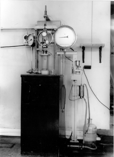
Drained triaxial tests on clay require a long time and the apparatus needs to be at a constant temperature, so we installed two machines in the BRS concrete lab with constant temperature and humidity. The lab had no windows and I decided to take readings through a long, slow test, by photography. I obtained a 35 mm clockwork camera with an electric shutter, and mounted it with a floodlight and an electric timing apparatus made by Cheney, which switched the light on a few moments before releasing the camera shutter. By moving the drainage burette up beside the proving ring and strain dial gauges, I obtained readings day and night which I read off on the library microfiche reader. For K0 tests, I used Bishop's mercury pots to apply cell pressure, and raised them at a steady, slow rate with a Meccano winch driven by a synchronous motor. With electrical contacts on the mercury indicator of a Bishop belly band, reduction of sample diameter started up the main motor of the triaxial loading frame, through relays, and increased the vertical compressive stress until the original diameter was restored. For these tests, a pressure gauge showing cell pressure was grouped with the other dials. It was necessary to add a little Indian ink to the burette so that it could be read from the negatives. Unfortunately, this excellent bit of apparatus never got written up.
3.9. Sampling
Another useful little gadget that never got written up, was to help to reduce disturbance and obtain full sample tubes. In general, samples taken by 1½ in. brass tubes or U4 sample tubes were obtained by pressing or driving the tubes into the ground at the bottom of a borehole, turning the sample tube with the intension of shearing off the sample from the parent soil, and pulling the tube out. Sometimes the sample stayed in the ground and often the retrieved sample was not full length. The distortions that can be caused to the sample by this method have been illustrated in Fig. 8 (part 2). Improvements to the driving heads for the U4s included an overdrive space, so that a sample could be taken right through the sample tube without it being compressed by the head, and a rubber flap valve to let out water from above the sample as it was taken, yet prevent return of water on withdrawal, to help retain the sample. But what was supposed to happen at the bottom of the sample as it was withdrawn? Either the soil closed in or water flowed in, in some way, or there was a vacuum formed. My solution was to use a small diameter copper pipe to pass air to the cutting edge of the sample tube to fill the space left by the sample. I strapped the tube to the side of the U4 with screw hose clips, and connected a long length of small plastic tube with a car tyre valve on its upper end. When the sample tube had been fully driven (or pressed), I used my car foot pump to blow air down the small pipe as the sample tube was withdrawn. Full length samples were obtained every time. The idea was taken up by Serota, head of Costains soils laboratory, and I think he may have mentioned it in one of his publications.12 Recently (1997) Professor Burland told me that this idea was being used when taking samples from under the footings of the Cathedral of Mexico City where sampling tubes are being used to extract clay to lower some foundations so as to reduce the damaging differential settlements that have developed over the years.
In the final Part 4 of this essay, we will begin with the 2nd International Conference on SM&FE of 1948 and continue to the 4th Conference held in London in 1957.

