In the construction of civil structures, the strength of the foundation is of high importance. Thus, engineers face many challenges, such as bearing capacity, settlement and high groundwater level, particularly if the structure is on sandy soil. To deal with these problems, solutions have been proposed, one of which is the use of skirted foundations. In this method, walls skirt the surface foundation and are buried deep in the soil. In this study, numerical analysis, taking into account the parameters of different lengths of skirted foundation walls, different percentages of soil densities and wall thickness, has been used to investigate skirted foundations under static loads. On the basis of the obtained results, a series of charts are presented for estimating bearing capacity improvement. Skirted foundations resting on denser sand provide better results in terms of bearing capacity than foundations resting on medium and loose sand.
Notation
- B
width of footing
- Df
depth of footing
- Dr
relative density of sand
- EA
normal stiffness (kN/m)
- EI
flexural rigidity (kN/m2/m)
- Es
elastic modulus (MPa)
- L
depth to the lower edge of the skirt below the footing base
- L/B
ratio of skirt depth to foundation diameter
- Nq, Nγ
bearing capacity factors
- qsk
bearing capacity of skirted foundations
- qsu
bearing capacity of surface foundations
- qu
ultimate bearing capacity
- Sq, Sγ
shape factors
- t
wall thickness
- γd
unit weight of the dry soil
- Φ
peak friction angle of the sand
- Ψ
dilation angle (degrees)
Introduction
The foundation is the lowest part of a structure that continues the load of the structure under the ground. The foundation design engineer must consider the bearing capacity of the soil under the foundation. This bearing capacity is described as soil strength in supporting the foundation load of the structures above. The bearing capacity indicates the shear strength of the soil against subsidence caused by loading (Nowzari-Joybari and Afzali-Rad, 2016).
The term ‘skirted foundations’ is used for semi-deep foundations, where the thin, fixed vertical structural elements along the sides are called the skirt. The skirts form a chamber in which the soil is enclosed to form a united element with the underground base and to transfer the load of the upper structure to the depth of the soil. Load is mainly located at the tip of the skirts (Golmoghani-Ebrahimi and Rowshanzamir, 2013).
Due to the importance of construction of foundations, the use of skirted foundations can be an effective aid in improving the bearing capacity and reducing the corresponding subsidence of structural foundations (Hamayoon et al., 2016; Latini and Zania, 2017; Michel et al., 2018; Morici et al., 2019).
Several studies have been conducted on the effect of the skirt length on this model of foundations in both the experimental and numerical fields; based on their results, the bearing capacity increases and the subsidence decreases accordingly with the increase in the length of the skirts. In this mechanism, where the load is applied vertically and suddenly on the surface of the foundation under study, as the length of the skirts increases, the volume of soil enclosed inside these skirts increases and the soil is integrated with the foundation system (Eid, 2013; EL Wakil, 2013; Mana et al., 2012; Villalobos, 2007). Also, the research results for applying horizontal or lateral loads on such foundations are almost similar to those for applying vertical loads. Based on this, the performance of the foundation model can be checked (Antoniou et al., 2022; El Wakil, 2010; Kannan and Chezhiyan, 2016; Thakare and Shukla., 2016).
Al-Aghbari and Mohamedzein (2006) studied the performance improvement of circular foundations due to surrounding skirts through loading test models. It was found that this strengthening and reinforcement increased the bearing capacity of the soil and improved the load–displacement response of the foundation. It was also found that the skirts reduced the displacement of the surface foundation compared with that of foundations without a skirt. At a pressure equal to 50% of the ultimate bearing capacity, the displacement of the foundation with a skirt was reduced to about 11% of that of a foundation without a skirt.
Zhan and Liu (2012) performed a series of finite-element analyses on the bearing capacity of a foundation by changing the position of the foundation from the bottom of a slope to the top of the slope and in the vicinity of the clay slope. They placed the skirted foundation located on the slope under vertical loading and the foundation adjacent to the slope under a combination of vertical and anchor loads. They concluded that the effect of the slope on the bearing capacity of the foundation was small when the foundation was located at the bottom of the slope. However, the failure mechanism was very different from that when the foundation was on the surface of the earth.
Soil compaction has a significant effect on improving the bearing capacity and reducing the corresponding settlement in skirted foundations, and as the compaction value increases, the results are better. Therefore, according to the results of other researchers, by increasing the soil compaction, the desired results are improved with the same skirt length compared with those for surface foundations without an accompanying skirt (Barari et al., 2021; EL Wakil, 2013; Le et al., 2021; Prasanth and Kumar, 2017).
The failure mechanism of such foundations depends on the length of their skirt. The failure mechanism occurs deep in the soil and under the skirt. Adding walls in the outer environment of the foundation changes the pattern in the interface between the foundation and the soil. The wall prevents the soil from settling under the foundation, and in this way, it traps the soil between the walls. Because of this, it transfers the failure wedges to the depths of the soil, and in this way, it increases the bearing capacity. With the increase in the length of the wall, failure wedges go from a shallow foundation to a deep foundation and a stress bubble is formed at the foot of the wall floor. Furthermore, a box foundation can be considered similar to a pile whose diameter is equal to the width of the foundation, and its perimeter is the surrounding walls of the foundation (Mana et al., 2010, 2012, 2013; Vulpe and Gourvenec, 2014).
Kourkoulis et al. (2014) evaluated the response of a soil–foundation–wind turbine interacting system subjected to earthquake shaking. Contrary to an often-prevailing impression that seismic effects are insignificant, apparently originating from evaluating the seismic behaviour on the basis of spectral characteristics, it is illustrated that the system kinematics may prove crucial for the response of large wind turbines subjected to simultaneous environmental and seismic loads. Although not instantly catastrophic, the accumulation of foundation rotation could lead to the turbine reaching serviceability limits early during its operation.
Despite the investigations and the results obtained for skirted foundations, the study of the performance of this type of foundation has been limited, so a more comprehensive investigation is needed. The purpose of this research is to investigate and evaluate the performance of square skirted foundations under static and seismic compressive loading and also to study the effect of different parameters on the behaviour of this type of foundation, which was done by numerical modelling in sandy soil. The present study concentrates on the bearing capacity of square skirted foundations subjected to vertical compression statics and seismic loads, using an extensive numerical testing program. The main variables evaluated in this study are the skirt depth (L), relative density of sand (Dr) and aspect ratio (ratio of skirt depth to foundation diameter; L/B).
Materials and methods
The behaviour of the materials was modelled using the Mohr–Coulomb failure criterion and considering an elastic–plastic behaviour. The soil parameters used in behavioural models were recorded according to the information obtained in the experiments by Sajjad and Masoud (2018); they are given in Table 1.
Materials
The foundations were made of steel. For modelling their linear elastic behaviour, a Poisson’s ratio of 0.3 and a Young’s modulus of 210 GPa were used. In the finite-element software, the skirted foundation design was modelled from a linear cubic mesh with eight nodes. In the work of Sajjad and Masoud (2018), Firuzkoh siliceous sand with a medium grain size was used as the soil under the foundation; according to the uniform (unified) classification system, this is a poorly graded uniform sand designated SP (ASTM, 2006).
Numerical method
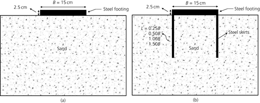
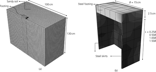
To carry out studies on the behaviour of the skirted foundation system, complete three-dimensional (3D) modelling of a square surface foundation with a width of 15 cm and a thickness of 2.5 cm and dimensions of the soil as a square with sides of 130 cm and a depth of 100 cm was considered. Also, skirts with length-to-width (L/B) ratios of 0.25, 0.5, 1.00 and 1.50 and with soil compaction percentages of 35, 50 and 75% and, to study the influence of the thickness of the skirts, four skirt thicknesses t/B of 0.013, 0.026, 0.04 and 0.053 were modelled. Figure 1 shows a side view of the model structure.
The finite-element numerical test was performed using the Abaqus software. The desired dimensions were modelled in the software. In Figure 2, the model designed in the software is shown. Figure 2(a) shows the general model of the skirted foundation buried in the soil, and Figure 2(b) shows the cross-sectional modelling of the skirted foundation from the side view.
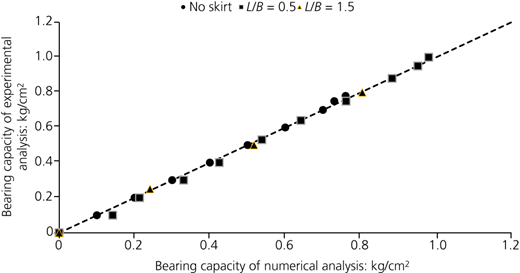
The primary objective of this study is to conduct a numerical enquiry into the behaviour of skirted footings under vertical loads. The experimental data from Sajjad and Masoud (2018) was used to determine the attributes of various constituents. By comparing the bearing capacity responses (numerical–experimental analysis) from the model footing test data with the finite-element results, the validity of the numerical analysis was confirmed, as Figure 3 indicates.
In the analysis, to minimise the boundary effects, the vertical boundary at the far end, on the sides, is assumed to have a rigid subsoil layer. Due to the displacement boundary conditions, no displacements were allowed in directions perpendicular to the planes. In the lower boundary of the built model, the displacement in all directions is equal to zero, and in the end lateral boundaries of the soil, the displacement in two directions (Y) and (X) is considered zero. In the dynamic model, it was necessary to define the soil layers as infinite. This is because the seismic stress wave in the soil layer does not reflect the boundary conditions, which could change the result. Therefore, an infinite element was used in the software.
Analysis and discussion of the results for static loads
The analysis of numerical modelling results show that the inclusion of the skirt improves the bearing capacity of surface foundations on sand. Size improvement increases with the increasing skirt depth. A quantitative analysis of such observed improvement is presented in the following sections.
Bearing capacity
Investigation of various parameters such as skirt length, soil density, wall resistance and tip resistance in sandy soil was carried out according to the bearing capacity determined for all types of models. The bearing capacities of skirted foundation models (q sk) and the surface foundation model without a skirt (q su) were compared (Hansen, 1970; Esfeh and Kaynia, 2020; Yao et al., 2021).
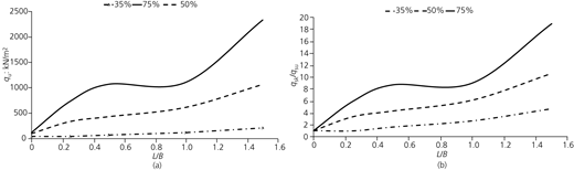
In Figure 4(a), the final bearing capacities of the surface foundation and skirted foundations with L/B of 0.25, 0.5, 1.00 and 1.50 and soil density percentages of 35, 50 and 75% are compared. According to the results, the final bearing capacity increased with the increase in the length of the skirt and also with the increase in soil density. The incorporation of the skirt was more effective in increasing the bearing capacity on sandy soil with a high density than on one with a low density. In Figure 4(b), the graphs of the q sk/q su ratios with different L/B values and measured for three percentages of soil density – that is, 35, 50 and 75% – are compared. This rate represents the ratio of the bearing capacity of foundations with skirts (q sk) to the bearing capacity of surface foundations (q su). Numerical investigations show that in surface foundations with no skirt, the rates of q sk/q su are equal in different soil densities, but with the addition of a skirt, this rate increases due to the increase in soil density. For example, if considering L/B = 1, the q sk/q su rate increases with the increase in soil density from 35 to 75%.
Research has been done based on different densities and L/B values of 0.25, 0.50, 1.00 and 1.50. With the increasing percentage of compaction, the impact of the lateral skirting on the load capacity increases. Figure 5 shows that for each skirted foundation, the ratio q sk/q su increases with the increase in soil density, and this ratio is almost constant for a non-skirted surface foundation. For example, for an L/B of 1.5 at a soil density of 35%, the q sk/q su ratio is 4.67, and the same ratio is 18.93 for a 75% density. If a line is drawn parallel to the horizontal axis (i.e., the relative density) – for example, if q sk/q su = 5 is considered – the L/B: 1.5 plot will intersect at a relative density of approximately 35%. The L/B: 0.25 line intersects it at between 65% and 70%. Now, if a line is drawn parallel to the vertical axis (i.e., the load capacity rate) – for example, if D r = 50% is considered – the L/B: 0.25 plot will intersect it at approximately q sk/q su = 3 and the L/B: 1.5 plot will intersect it at approximately q sk/q su = 10.5.
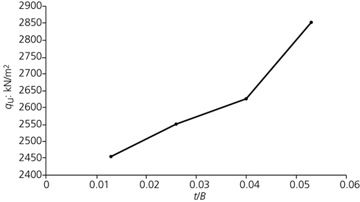
Figure 6 shows the q u–t/B diagram, where q u is the final bearing capacity, t is the wall thickness and B is the width of the skirted foundation. Considering L/B = 1.5 and t/B values of 0.013, 0.026, 0.04 and 0.053 with a soil density percentage of 50%, analysis of controlled strain type was done to reach the bearing capacity. The obtained results are not much different from each other, and in general, the average value of t/B can be used as the design thickness. What is important is the desired value of the designer; in accordance with the obtained values, they should set the desired thickness in their design as a criterion.
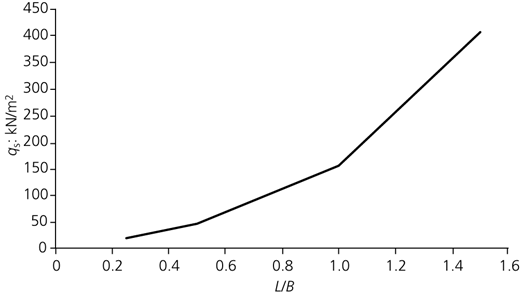
In this part, a skirted surface foundation with L/B of 0.25, 0.50, 1.00 and 1.50 and with a soil density of 50% was analysed using the strain-controlled method, and the results for the shaft part, shown in Figure 7, were investigated; this is called the shaft resistance. According to the results obtained, as the length of the skirt wall increases, the shaft resistance also increases, which is due to the increase in the amount of friction between the wall and the soil.
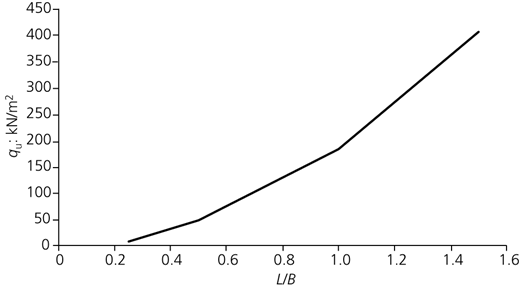
Due to the increase in the length of the skirts and the increase in the area of the skirts that is in contact with the soil, the resistance value of the tip also increases proportionally, which is clearly visible in the diagram in Figure 8.
The ultimate bearing capacity of surface and skirted foundations has been presented through proposed and theoretical relationships by various researchers, including Hansen (1970) and Meyerhof (1963), taking into account the shape and depth of the foundation and other factors, which is in the form of Equation 1, where s q and s γ are shape factors and d q and d γ are depth factors.
The factor γ is the mean unit weight of soil; D f is the depth to the footing base below ground; and B is the footing width. The values of N q and N γ are factors related to the Terzaghi (1943) relativity, which comes from the internal friction angle (φ).
For square foundations with a skirted structure that are placed on sand and subjected to central and vertical loads, changes in the overall ultimate bearing capacity equation are required. These are as follows.
The length of the skirt L is added to the depth of the footing D f so that (D f + L) is written instead of D f in Equation 1.
According to Al-Aghbari and Mohamedzein (2020), to determine the final bearing capacity of shallow foundations with a skirted structure, a factor (F γ) should be entered in the second part of the general equation to take into account all the features of the skirted structure of the foundation:
where D f is the depth below the ground surface and L is the depth or length of the skirt.
The skirt coefficient (F γ) is probably influenced by the skirt surface friction angle (δ s) and skirt depth (D s).
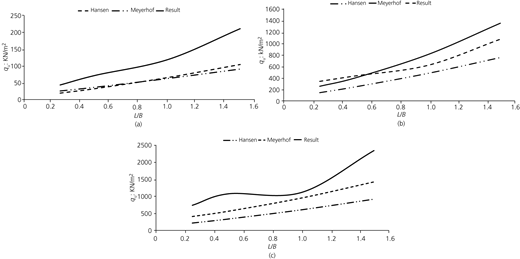
In Figure 9, the calculation diagram of the modified final bearing capacity formula of Hansen (1970) and Meyerhof (1963) is compared with the diagram of the numerical calculations performed for densities of 35, 50 and 75%. It can be seen that bearing capacity ratios (BCRs) calculated using the equation are in reasonable agreement with the cases of numerical analysis.
Analysis and discussion of the results for seismic loads
The focus is on the soil bounded between the skirts, which is expected to be improved from one case to another, starting with modelling the soil without skirts and finishing with skirts with a ratio L = 1.5B. Thus, there is an enhancement in the characteristics, primarily in the displacement and acceleration. Thus, the presence of skirts improves the soil properties. The existence of skirts causes confinement of the soil domain underneath the foundations, and the soil mass is expected to resist higher stress from the vertical loads (Padrón et al., 2008).
Numerical method
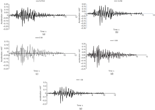
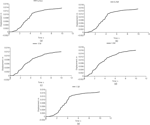
A series of foundation models with and without skirts are considered and investigated. Skirts with different depths are considered with L/B = 0.25, L/B = 0.50, L/B = 1.00 and L/B = 1.50. The soil consists of a deposit of a sand layer of 1.3 m thickness, and it is linear elastic in dynamic analysis. The assumed properties of the studied sand are as follows: γ dry = 15.87 kN/m3, ν = 0.3, E = 35 000 kN/m2, shear angle φ = 39° and dilatancy angle ψ = 9°. The material type is assumed to be undrained; the material adopted model is Mohr–Coulomb. Rayleigh damping is considered at vertical boundaries with α, β = 0.01 in order to reduce the Rayleigh waves and to define the plastic properties of soil (viscous) properties of the soil. The model foundation properties are mentioned in this paper. The properties of the skirted steel are EA = 8.000 × 10⁶ kN/m, EI = 1066.667 (kN/m2)/m, thickness t = 0.03 m and ν = 0.3, and the weight of the skirted steel w = 3.12 (kN/m)/m. The rest displacement is zero, and the time interval = 10.0 s. The time history of the acceleration used in this project is the 1989 Loma Prieta, USA, earthquake. In this analysis, acceleration–time and displacement–time graphs are plotted.
Analysis and discussion of the results for seismic loads
The acceleration–time history is one of the significant characteristics of the dynamic behaviour of soils and foundations under earthquakes. Using skirts decreased the induced acceleration values. Furthermore, comparing the two cases of foundations with and without skirts, it can be seen that the confined zone between the skirts decreased the acceleration with great values. The graphs in Figure 10 show the effect of foundations with and without skirts on the time–acceleration parameter for the soil directly under the foundation. This figure shows reductions in vertical acceleration of around 84.4 and 85.2%, respectively, for the case of a skirted foundation with L = 1.5B. The effect of such skirts on the soil body and the vertical acceleration is shown in this figure. It is found that the skirts reduced the foundation vertical acceleration up to around 86% at a skirt depth ratio of L/B = 1.5.
Figure 11 shows a reduction in vertical displacements by around 80% for the case of a skirted foundation with L = 1.5B. Using steel skirts has a positive impact on improving the response, as confirmed by Figure 11. It is found that the skirts reduced the vertical displacements by about 80% at a skirt depth ratio L/B = 1.5.
From these figures, it can be concluded that implementing the skirts is a good technique to reduce both displacements and acceleration in vertical directions. The skirts could enhance the foundation resistance, which in turn might result in significant improvement of the structure response to earthquake loading.
Conclusion
The purpose of this study was to investigate the behaviour of skirted foundations under vertical load. In other words, it was investigated what effect the peripheral walls had on the bearing capacity compared with the surface foundation and what impact will an increase in height, changes in the thickness of the walls and the change in soil compaction have on its bearing capacity and its corresponding settlement.
The most important results of this research are as follows.
The walls trap the soil inside the foundation, and this causes the wedge failure to move deep into the soil; so, with the increase in the length of the walls, a stress bubble is formed at the foot of the walls, thus increasing the bearing capacity and its corresponding settlement.
With the increase in soil compaction, the final bearing capacity increases. For example, the rate of increase in bearing capacity for L/B = 1.5 is 210.71 kN/m2 for soil compaction of 35%, 1067.62 kN/m2 for 50% soil compaction and 2336 kN/m2 for 75% soil compaction. Moreover, for soil with constant compaction, the final bearing capacity increases with increasing length of the enclosing wall. For example, for soil compaction of 50%, an increase from L/B = 0.25 to L/B = 1.50 increases the final load capacity from 337.34 to 1067.62 kN/m2.
By increasing the thickness of the walls from 0.013B to 0.053B, the final bearing capacity increases from 2455 to 2852 kN/m2.
The BCR increases with increasing depth of the skirts and soil compaction.
By increasing the length of the skirts, which leads to an increase in the amount of the area involved with the soil, the wall resistance also increases.
As the length of the skirt increases, the resistance value of the tip increases.
The skirts can decrease both the vertical displacement and acceleration of the system by as much as 80%.