
The Kinta Formation is one of the prominent and complex karst formations in Malaysia. Karst ground has an abundance of cavities, solution channels, pinnacles, overhangs and floaters. Design and construction of foundations in such ground conditions are complicated. If a given site has karst geology and is an also ex-mining ground, the challenges are compounded. Often, generalised and one-size-fits-all designs are used in geotechnical engineering. However, in such unpredictable and challenging soil conditions, this approach can be either conservative or unsafe. An interactive geotechnical design approach is vital to achieving an economical and practical solution. In this paper, the role of interactive design in foundation design and construction of a lime-processing plant in Malaysia is discussed. The site, located in the eastern part of Peninsular Malaysia, sits within the bounds of the Kinta Formation and was a former tin-mining ground. Over the 34 ha of the project site, earthworks and foundations were required to be executed. Some examples of solutions derived by interactive design in geotechnical engineering as applied to this project are discussed.
Introduction
An interactive geotechnical design is a design approach that requires design refinement throughout the project execution period until a suitable technique and an optimum scheme are applied to the problem at hand. This approach would require the involvement of the geotechnical engineer early in the project, from directing the soil investigation (SI) works, design and execution right up to instrumentation and performance monitoring.
In general, the use of interactive geotechnical design is not frequent. For most projects, design solutions are finalised before the execution begins and there is very little likelihood of changing the design, even when actual ground conditions are distinctly different from what was assumed in design. The traditional design approach inevitably requires designers to apply conservative solutions.
The following paragraphs will address the distinctive design approach that was used for the development of a plant on karst and ex-mining ground. An interactive geotechnical design approach was applied to the design of foundations for the plant.
Karst geology
The Kinta Valley karst is the most extensive karst formation in Malaysia. It is a typical tropical karst, characterised by prominent limestone towers or mogotes that rise from the surrounding alluvial floodplains. The Kinta Limestone is a thick limestone formation and underlies a relatively shallow, mineral-rich alluvium (Tan, 2009).
Karst topography is dotted with cavities, ravines, interconnected subterranean channels, pinnacles, overhangs, floaters and slump zones (Tan, 2009; Waltham and Fookes, 2003). These features, in addition to highly erratic bedrock profiles, make karsts one of the most challenging ground conditions with regard to geotechnical engineering.
Ex-mining ground
Historically, the Kinta Valley was the most productive tin-mining district in the world and was dubbed as the ‘Valley of Tin’ (Rajah, 1979). Beginning from the second half of the nineteenth century up until the 1960s, the valley was the main contributor to Malaysia’s tin exports, making Malaysia the leading supplier of tin in the world (Rajah, 1979). However, by the mid-1980s, most of the tin mines were shut down, owing to the sharp drop in the demand for tin worldwide and higher operational costs of mines. Unfortunately, the rich legacy of century-long mining activities left behind wastelands with thousands of ex-mining ponds and thousands of tonnes of tailing soils haphazardly strewn throughout the valley.
Consequently, the engineering challenges for rehabilitating ex-mining grounds are substantial. Due to the nature of their placement, tailings are usually in a loose state. Such a condition makes ex-mining soils susceptible to liquefaction at low vibrations and higher compressibility when subjected to nominal loading. A good example is the phenomenon of sinkhole formation within the Kinta Valley after the December 2004 Sumatran earthquake. Due to the earthquake and subsequent aftershocks, some ex-mining areas experienced sinkhole formations (Muhammad et al., 2011). The tailings are in a metastable state and highly susceptible to large deformation under load. Various rehabilitation measures have been applied in Malaysia, some of which were documented by Yee (2012).
Project information
Background
The project site is located on the south end of the Kinta Valley and is close to the geological interface of the Kinta Limestone and Main Range granite intrusion. When the project owner acquired the land for development, about 20% (by area) was initially covered by ex-mining ponds (refer to Figure 1). The site had a flat terrain and surface drainage was generally southwards.
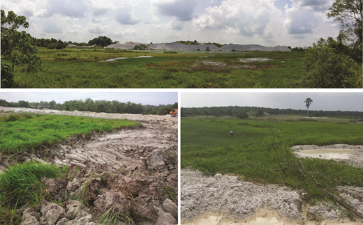
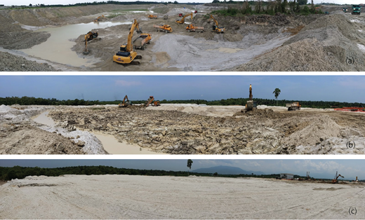
Photographs of the site before the start of works show an abundance of ponds, slime and vegetation
Photographs of the site before the start of works show an abundance of ponds, slime and vegetation
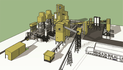
The proposed development comprises the construction of a lime-processing plant. The proposed plant, owned by a multinational lime manufacturer, is envisioned to become the biggest lime-manufacturing plant in South-east Asia and will produce high-grade lime to be used by metallurgy, paper, oil and gas, plastic and cement industries in both local and regional markets. The plant construction consisted of essential structures such as kilns and lime silos more than 50 m high. The development includes lime processing, packaging, storage, weighing, truck/container loading facilities and an energy plant. It also has its own quarry and crushing facility. About 35 different structures were required to be built. Also, a conveyor and pipe rack system about 1·5 km long was required to be constructed. Figure 2 shows the three-dimensional (3D) rendered view of the lime-processing plant. The performance criteria needed for different structures are given in Table 1.
Typical performance criteria for buildings/structures
| Most process structures and silos |
|
| Sensitive equipment |
|
| Flat-bottom tanks, pipe racks, conveyors |
|
| Coal and limestone stockpiles |
|
Preliminary stage SI
Within the site, a total of 84 boreholes and 18 piezocones (cone penetration tests (CPTs)) were sunk in two stages for preliminary studies. Based on SI information from boreholes and CPTs, the soils were categorised into two types: alluvium (quaternary deposits) and tailing soils. Alluvial soils dominated the western part of the site and covered about half of the site. These cohesive soils were seen to be of intermediate to high plasticity, with plasticity index ranging from 20 to 40%. This portion of the site was mostly swampy, low-lying and had lush vegetation cover.
Mine tailings dominated the other half of the site. These heterogeneous tailing soils were observed to be mostly loose, silty sands frequently interbedded with silt or clay lenses. In specific areas, slime dominated from the original ground level up to about a depth of 6 m. The slime layers were mostly clayey silts (50–90% silt content), usually followed by loose silty sands.
Bedrock was encountered in all boreholes. The limestone was seen to have a very erratic profile and incidence depth, which is typical in karst geology. Cavities, both empty and infilled, were intercepted by about 15% of the boreholes. The thickness of cavities ranged from 1·5 to 4·5 m, and the ceiling rock thickness above the cavities ranged between 1·5 and 7·5 m. At least five boreholes showed the presence of pinnacles in the bedrock. Boulders or overhang limestone was evidenced in two boreholes. The limestone bedrock can be characterised as a highly weathered to massive rock, with rock quality designations ranging from 0 to 50% at the incidence and improving with depth. The unconfined compressive strength (UCS) for the rock samples ranged from 20 to 70 MPa.
Interactive geotechnical design
Since the project site encompassed both ex-mining and karst grounds, the geotechnical issues were numerous. Potential geotechnical risks for the site were identified, such as deep bedrock levels making it impractical for piles to reach sound bearing levels and highly compressible overburden soils and disturbed tailing soils that require extensive treatment. Moreover, the erratic limestone profile and the presence of overhang limestone (or floaters) results in difficulty for pile installation, and the potentially extensive and well-connected network of solution channels and cavities may lead to sinkholes and cavity roof collapse.
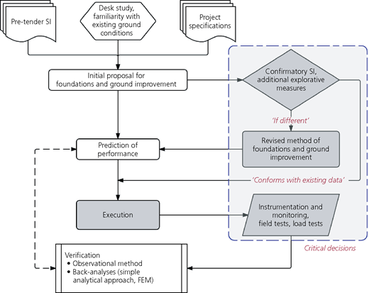
Based on these risks and previous experiences in similar ground conditions, it was evident that for successful execution of the project, an interactive approach to geotechnical design was necessary from the outset. The active involvement of the geotechnical engineer throughout the design stage, in proposing additional investigative works, execution, field monitoring and up to project handover was vital. Frequent communications were required between the owner, project manager and geotechnical engineer regarding design modifications and alterations. Continuous verification of design parameters was ensured by monitoring field data, field tests and proof load tests. Whenever design parameters were not met, the design was quickly modified or altered altogether to achieve the project requirements. The interactive design procedure that was followed is illustrated in the flow chart in Figure 3.
A conceptual framework for interactive design as applied on the current project. FEM, finite-element method
A conceptual framework for interactive design as applied on the current project. FEM, finite-element method
Further SI works
The need for additional SI before construction started was paramount as some areas had too few reference boreholes for optimised design. Given the highly heterogeneous nature of the ground in ex-mining regions, accurate SI information was vital to characterise ground conditions in different areas of the site and specify appropriate geotechnical solutions. There were multiple changes to the plant master plan and footprint area of structures, leaving some critical structures without reference boreholes or qualitative SI data. Moreover, the initial SI was concentrated at specific locations, and areas near ponds and soft zones were not captured.
Soil characterisation
A comprehensive subsurface investigation comprising CPTs and rock probing was carried out. The primary objective of CPTs was to demarcate soil zonings properly and to characterise the soils, such that the most appropriate geotechnical solution can be applied. For this reason, initially, 80 CPTs were planned. These were required to continue until refusal or 30 m depth, whichever came first. During construction, additional CPTs were carried out. By the end of the project, in total, 125 CPTs were done. About 20 dissipation tests were also carried out in areas where clayey alluvial soils and slime layers were encountered.
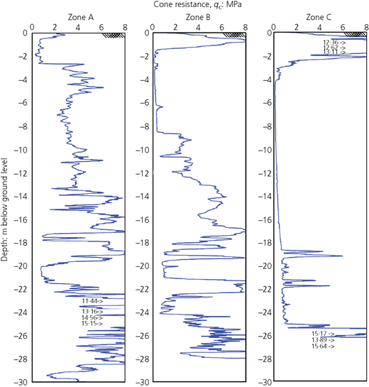
Based on total SI information, zonings for geotechnical design were made. The project site was subdivided into three different zones. Zone A comprised areas where loose-to-medium dense sands or silty sands dominated up to the bedrock, whereas zone B covered areas where soft slime layers or alluvial clay overlying sands and silty sands were less than 6·0 m. Zone C represented the remaining areas where the overburden consisted of very soft-to-medium stiff alluvial clays and silts. Figure 4 shows comparative plots of cone tip resistance (qc) against depth of some typical CPTs within the respective zones.
The original geotechnical zoning and one that was developed after the extensive SI works are shown in Figures 5 and 6, respectively. Such geotechnical plans provided the basis for determining the appropriate types of foundations or ground improvement to be used. For zone A, the kind of foundation proposed was shallow foundations for lighter loads or improvement with vibro compaction where there was a risk of liquefaction. In zones B and C, it was evident that the top compressible cohesive soils had to be improved, and vibro replacement (stone columns) was used to achieve this. In all zones of intermediate-to-high column loads, driven piles were proposed, and for highly loaded and sensitive structures, bored piles were recommended.
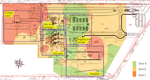
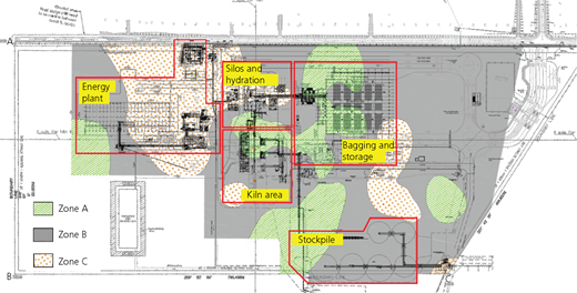
Diagram of geotechnical zoning for the site after carrying out supplementary SI works
Diagram of geotechnical zoning for the site after carrying out supplementary SI works
Rock profile
Where deep foundations were proposed, rock probing was necessary to map out the rock profile below the structure footprint. All probing points were specified to prove limestone bedrock (i.e. not a floater or overhang) and to treat any cavity that was intercepted. For structures to be supported on driven piles, probing was required to continue 2·0 m into the rock head to ensure that the piles do not terminate on top of thin limestone caps overlying a cavity, whereas for bored piles, rock probing was required to continue into the bedrock for the total length of the rock socket length plus 1·5 m.
In several locations, slumped zones were encountered while carrying out the rock-probing works. Slumped zones are features of karst geology where a collapsible weak soil zone overlies the limestone bedrock (Tan, 2009). This zone of weak soils is easily identifiable since the standard penetration test blow count (SPT-N) or the cone tip resistance (qc) is meagre (typically SPT-N < 2; for CPTs, qc < 0·25 MPa, Rf < 1%). Such features need a careful drilling and grouting approach, as the slumped zone is very friable and any disturbance (e.g. excessive water flushing while drilling or withdrawal of drilling rods or casing without treatment) can potentially cause collapse. In the event of a disturbance, a sinkhole or a slump depression is likely to occur.
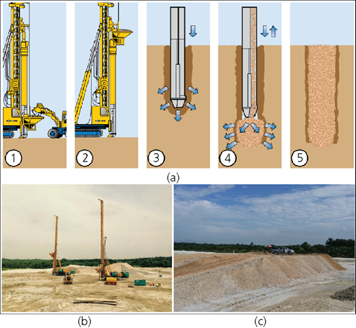
Cavities and floaters were also identified in some areas during the rock-probing works. All anomalies encountered during rock probing were treated with compaction grout using low-mobility mortar. This grout squeezes the loose soils within the cavity, forcing the soil particles to be displaced and compacted, which in turn helps to stabilise the cavity within the karst limestone. Figure 7 shows the different applications of compaction grout in karst areas. In total, 135 rock-probing points were carried out (about 4500 linear m) and about 300 m3 of mortar was pumped.
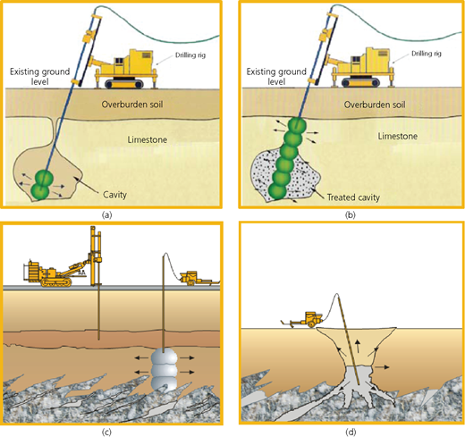
Process diagram of compaction grouting works in karst geology. Cavity probing (a) and grouting (b) schematics (after Raju and Yee (2006)) and the use of compaction grouting for weak zone treatment (c) and sinkhole treatment (d)
Process diagram of compaction grouting works in karst geology. Cavity probing (a) and grouting (b) schematics (after Raju and Yee (2006)) and the use of compaction grouting for weak zone treatment (c) and sinkhole treatment (d)
Figure 8 shows soil profile cross-sections across the plant (a) based on original information and (b) refined after incorporating the additional soil and rock investigation works. There is a stark difference in most locations, which consequently resulted in the change of treatment types for the affected areas.
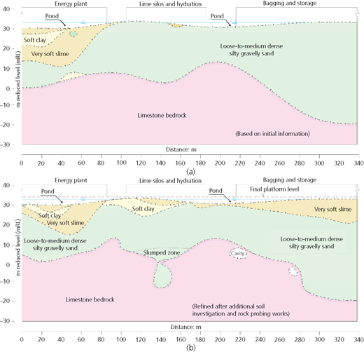
Soil profile cross-sections across the plant based on (a) initial information and (b) data from additional investigative works
Soil profile cross-sections across the plant based on (a) initial information and (b) data from additional investigative works
Monitoring and testing
Instrumentation is a vital part of an interactive design since the performance of the design can be precisely gauged. It can also be used as part and parcel of the observational methodology to complement design procedures, allowing the design to be modified and recalibrated during construction, to suit the actual site performance better.
An instrumentation and performance monitoring programme was developed based on the following principles: (a) to enable subsequent verification of the design assumption; (b) to cover selected representative areas to define the performance of ground improvement and foundations; and (c) to record and process monitoring data to enable data evaluation at any time on request of the operational needs. Instrumentation included rod settlement gauges (RSGs), ground and wall settlement markers, piezometers and inclinometers, installed at various locations – mainly where ground improvement techniques were used.
Post-treatment testing was also part of the interactive design approach. Such tests were necessary to confirm that design requirements were met. The testing programme included field density tests, pre- and post-treatment CPTs, plate load tests on vibro stone columns, plate bearing tests for shallow foundations, a maintained load test on preliminary test piles, a maintained load test on working piles and high-strain (pile driving analyser (PDA)) and low-strain (pile integrity test) dynamic tests on selected piles.
Back-analyses
Back-analyses were necessary to recalibrate or verify some of the design assumptions. In some cases, where ground improvement was used, the initial designs were altered as additional SI or instrumentation results were received.
For ground improvement areas, such as vibro stone column treatment areas, the back-analysis was used to decide when to remove surcharge fills. Initial estimates of time and rate of consolidation were predicted using the Han and Ye (2001) approach. In the field, the observational method was used to ensure that the requirements were met. Asaoka’s (1978) graphical settlement method was used to predict the remaining settlements and estimate the time remaining to achieve the targeted degree of consolidation. For deep foundations, the rock socketing length of bored cast-in-situ piles was optimised based on preliminary load test results. All the installation rigs for ground improvement and deep foundations were also equipped with real-time monitoring, which enabled better-quality control and a faster response to any deviation from the design assumptions.
Examples of application
Ground improvement
Depending on ground conditions, nature of loading and performance criteria, ground improvement methods used include (a) soil replacement and compaction methods for unsuitable soils of shallow depth; (b) vibro compaction, where extensive loose, clean sands were found; and (c) vibro replacement (also known as vibro stone columns), where thick, cohesive compressible soils were encountered.
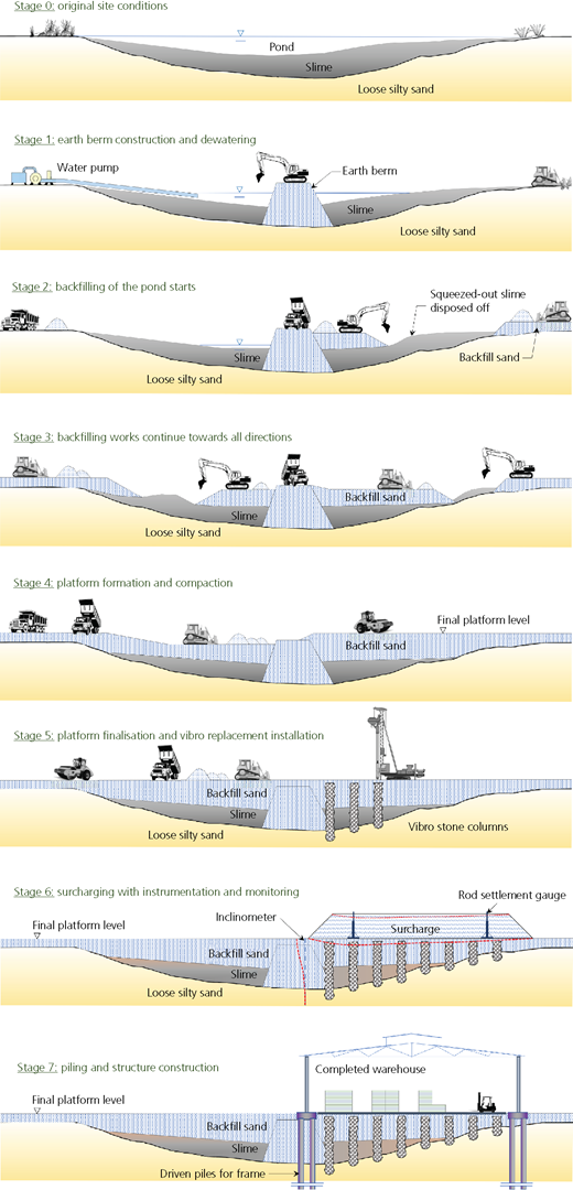
The project involved significant quantities of earthworks, such as cut-and-fill works to bring the site to the desired platform level and excavation for sedimentation ponds and within the designated borrow-pit area where the rock needed to be exposed for mining. Due to the presence of ex-mining features such as ponds and unsuitable soft layers, most of the site required a degree of backfilling. Suitable materials were excavated from the borrow pit and transported to the project site for filling works. The filling needed to be done layer by layer and compacted until 90% relative compaction was achieved. Filling of the ponds was very challenging, as it was difficult to place thin layers and to compact them layer by layer. Figure 9 provides examples of the different processes involved in the earthworks, while Figure 10 shows the construction sequence during the earthworks. In such cases, thicker fills with nominal compaction were formed, which were then compacted adequately once a stable platform was created. Field density checks were then carried out to ensure that the placed fill has met the project requirements. Overall, about 2 million m3 of earth was handled in the project.
Earthworks and excavation work in pictures: (a) borrow pit area for fill sourcing; (b) soil berm construction, filling and slime removal; (c) completed platform, fill works finished up to the final fill level
Earthworks and excavation work in pictures: (a) borrow pit area for fill sourcing; (b) soil berm construction, filling and slime removal; (c) completed platform, fill works finished up to the final fill level
For lightly loaded areas and areas where shallow unsuitable soil layers dominated (very soft slime or clay layers), soil replacement or compaction-related ground improvement methods were applied. Such areas included roads and light structures in zones A and B. The adopted methods were a combination of surface compaction, rapid impact compaction and remove-and-replace methods. Rapid impact compaction was initially proposed for road areas in zones A and B. Rapid impact compaction is a compaction method that uses a 7–9 t hammer from a height of 0·80–1·20 m on an impact foot and at a frequency of 40–60 impacts per minute (refer to Figure 11 for the installation process). The impact foot continually remains in contact with the soil, allowing a higher efficiency in the compaction energy transfer compared to conventional dynamic compaction, in which the hammer can fall on an uneven surface and thus dissipate a significant portion of the impact energy to absorb the surface irregularities. Trials at different spacings were conducted on-site to check the effectiveness of this method. In zone A areas, although the performance was generally good, the presence of medium-dense sand layers occluded the dynamic energy from being transferred further below. In zone B areas, the haphazard presence of silt and clay lenses near the surface proved that this was not the best solution. Instead, the remove-and-replace method was used wherever necessary.
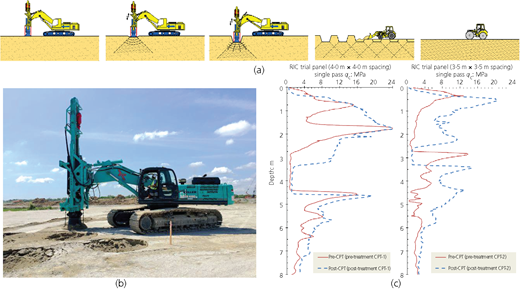
(a) Installation procedures for rapid impact compaction (RIC); (b) standard installation rig and crater formed due to compaction; (c) pre- and post-treatment cone penetration comparisons at trial areas
(a) Installation procedures for rapid impact compaction (RIC); (b) standard installation rig and crater formed due to compaction; (c) pre- and post-treatment cone penetration comparisons at trial areas
Vibro compaction was used for areas where there were clean, loose sands to depths of more than 10 m and where the fines content was less than 10%. Vibro compaction is a deep vibro technique that uses vibration energy from a depth vibrator to densify granular soils (refer to Figure 12 for the process diagram). This method was used most notably in zone A areas where massive and tall structures where situated. As the future mining area was intended to be very close to the project site, the effect of vibrations because of rock blasting was required consideration during foundation design of critical structures. The project requirements for the ground where vital structures were located was to be improved to a minimum of class SD as per the Uniform Building Code 1997 (ICBO, 1997) (soil profile type according to Table 16-J of the code). The foundation for these structures was designed as a piled raft foundation. In addition to preventing liquefaction, the compaction of the loose sands also helped to reduce the lateral loading due to the structural basal shear on the piles and proved to be a more economical solution. The loose sands, whose initial relative density was 40% or less, were required to be densified to a relative density of 70% or more. The general scheme adopted was to do vibro compaction at a spacing of 2·5–3·5 m up to depths of about 15 m. In most cases, the requirements were met after the first round of vibro compaction, although, in some instances, recompaction was necessary to achieve the requirements.
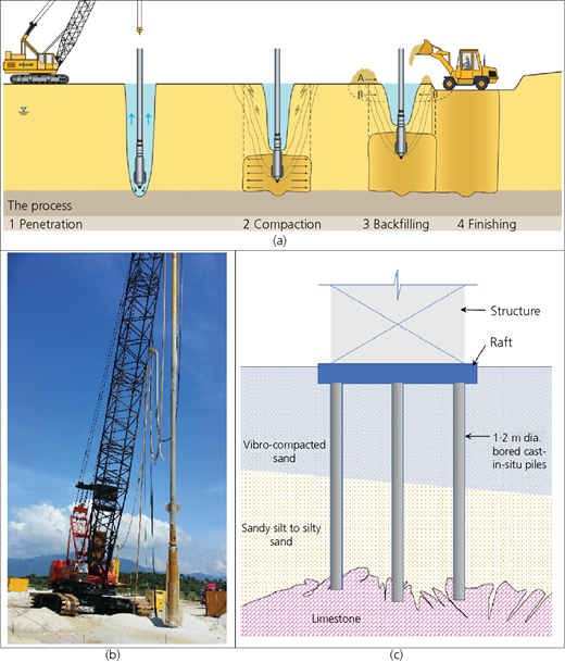
(a) Vibro compaction process diagram; (b) vibro compaction set-up on-site; (c) schematic illustration of how vibro compaction was used in combination with bored piles
(a) Vibro compaction process diagram; (b) vibro compaction set-up on-site; (c) schematic illustration of how vibro compaction was used in combination with bored piles
Vibro replacement was also used extensively in zones B and C to improve weak, soft layers. This method was used where other methods could not be applied due to the nature of the ground condition or performance requirements. Vibro replacement, or vibro stone columns, is a deep vibro technique that builds load-bearing columns made of crushed stone. Since the column is made of highly porous materials, the added benefit of vibro replacement is that it enhances consolidation by allowing the surrounding soils to drain. Vibro replacement has a good track record for treating ex-mining tailings and ultra-soft slimes in Malaysia (Raju and Hoffmann, 1996). Figure 13 shows the process diagram of vibro stone columns.
(a) Process diagram of vibro replacement; (b) vibro replacement rigs installing stone columns on-site; (c) surcharging ongoing at the warehouse area
(a) Process diagram of vibro replacement; (b) vibro replacement rigs installing stone columns on-site; (c) surcharging ongoing at the warehouse area
Vibro replacement was used for a big warehouse, a coal storage building and limestone stockpile areas. The big bagging warehouse is one of the primary structures intended to house the end product in bagged forms. The warehouse covers an estimated area of 11 500 m2 and is required to sustain an imposed loading of about 5 t/m2. Forklifts and container loader are intended to operate on the warehouse floor. Thus, it was required that permissible settlements within the warehouse during operation should be the same as those supported on a rigid foundation.
Based on preliminary SI, soil conditions within the structure’s footprint were interpreted to be uniform and predominantly comprise very loose clean sands up to the bedrock. Hence, the initial treatment proposed for this area was vibro compaction. Confirmatory SI consisting of six CPTs was carried out within the warehouse footprint. However, CPT results were found to be much different as slime layers were encountered in all of them. As such, 12 additional CPTs were sunk to investigate the thickness of compressible layers (refer to Figure 14). Distinct zones were identified for treatment purposes. Based on the additional SI data, it was shown that the warehouse almost wholly falls on ex-mining pond and tailings areas. The topsoil predominantly consisted of very soft-to-soft slime followed by very loose-to-medium dense silty sands. From this, it was evident that vibro compaction was not an appropriate solution, and vibro replacement was chosen instead. The vibro replacement-treated ground had to be surcharged to meet stringent performance criteria.
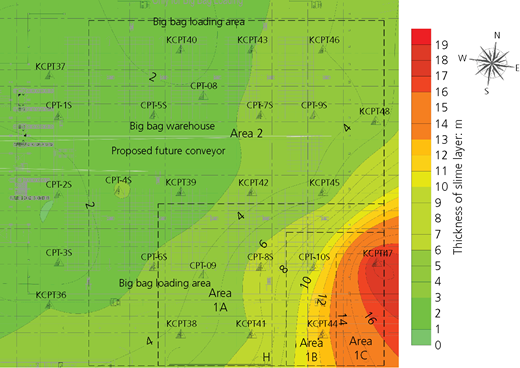
Diagram of mapping of the inferred thickness of very soft slime over the warehouse footprint
Diagram of mapping of the inferred thickness of very soft slime over the warehouse footprint
Vibro replacement with 13·6% area replacement ratio was proposed and installed at a uniform spacing throughout. The treatment depths varied by subzones, ranging between 5 and 12 m. To ensure that the slime layer was fully intercepted, the stone columns were required to continue for about 1·0 m into the underlying sands. During installation of stone columns, an additional area (area 1C) was identified, where the thickness of weak slime extended up to 18 m. For this area, treatment depth was quickly adjusted to 20 m and a higher area replacement ratio for the stone columns was used. Different surcharge heights for each subzone were proposed and applied to achieve the required degree of consolidation. Area 2 was surcharged by a nominally compacted sandy fill up to 3·5 m height (i.e. about 60 kPa), whereas in area 1 (1A, 1B and 1C), the surcharge height was planned to be 4·0 m (i.e. about 68 kPa).
A regime of instruments consisting of RSGs and surface settlement markers (SSMs) was installed to monitor performance. Resulting settlements during the filling process were recorded from RSGs at a frequency of twice per week. During the rest period, upon reaching full height, readings from both RSGs and SSMs were recorded at a frequency of once per week. Once settlements stabilised and a degree of consolidation of at least 90% was achieved, the monitoring was stopped and the surcharge was removed.
As many of the structures, including the warehouse, were situated partially on a mining pond, earth filling and platform preparation were necessary before carrying out any of the ground improvement works. As the ponds were dewatered, filling works began from the edges and moved towards the centre. If a pond were of significant size, an earth berm that dissects it would first be constructed. Successive filling then continued from the berm towards both sides while simultaneously filling from the outside towards the inside. It was usually necessary to skim off the slime that squeezes out during the filling works. The pond filling works proved to be a better approach than doing the filling from one side only, as the filled embankment could potentially slip if the filling is from one direction. Figure 10 illustrates the construction sequence followed from the earthworks stage to the ground improvement stage. Once the platform was prepared, vibro replacement columns were installed. After installation of the stone columns, the surcharge fill was applied and left for a specified rest period.
Settlements were monitored and back-analysed until the required degree of consolidations were attained. Figure 15 shows the surcharge fill height and consolidation settlement against time for area 1B of the warehouse. The settlements profile and magnitude as estimated by the Han and Ye (2001) method is observed to be close to the measured settlements in the field. Based on this, the residual settlements were estimated to be less than 10 mm.
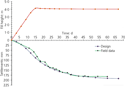
The plot of surcharge and consolidation settlement against time; comparison of predicted and actual consolidation settlements for area 1B of the warehouse
The plot of surcharge and consolidation settlement against time; comparison of predicted and actual consolidation settlements for area 1B of the warehouse
Deep foundations
Two types of deep foundations were adopted: bored piles and driven spun piles. For most structures, driven piles were used, while bored piles were used to support heavier loadings and structures with high lateral forces. Initially, preliminary test piles were installed to verify the parameters that were considered during the design stages. Due to the high variability of the ground conditions, frequent tests were required.
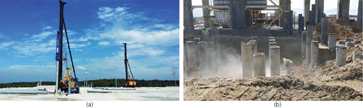
Driven pile installation in karst ground has numerous potential risks (Neoh, 1998). To minimise risks for piling works, it was necessary to define the estimated rock-head depths. In addition to information that existed from boreholes and CPTs, rock probing was carried out to determine rock-head depths (as elaborated in the section headed ‘Rock profile’). Moreover, set requirements were also specified such that the damage of piles during driving would be minimised. In the soil layers, the set criterion was 15 mm per 15 blows, whereas for rock, the set criterion was 3 mm per three blows with close observation of hammer rebound. Pre-stressed driven spun piles were selected for the site to ensure that the breakages were minimised (grade 80 and an effective pre-stressing pressure of 5 MPa). These piles also have better lateral loading capacity compared to square driven piles. Piles (300 and 500 mm dia.) were selected for use; a 25% downgrade in the structural capacity was allowed to safeguard the piles due to the conditions of the site. Figure 16 shows the installation of piles on-site and head cutting off to prepare for the casting of pile caps.
During the initial design stage, a single set of pile design parameters was assumed for the entire site. However, to account for highly variable ground conditions, at least one maintained load test was carried out in each geotechnical zone to establish the design parameters in each zone. High-strain dynamic tests were also carried out on 5% of the piles to ensure proper performance of working piles. Even though a higher pile breaking frequency was expected for driven piles in karst ground, for this site the actual frequency was insignificant. Five piles were identified as damaged, broken or driven beyond their expected depths out of about 1300 piles. These were eventually tested by PDA; three of them failed the test and were replaced. Figure 17 compares the PDA test results for driven piles against working load in all the zones. From the figure, it is evident that the skin resistance decreases from zone A to zone C and vice versa for the toe resistance.
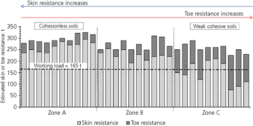
The plot of skin and toe resistances as evaluated from PDA tests and comparison against designed working load at different zones
The plot of skin and toe resistances as evaluated from PDA tests and comparison against designed working load at different zones
The interactive design approach was also followed for bored piles, particularly regarding rock socket lengths. Point load tests were carried out for each pile to ensure that the piles were socketed into competent rock. Based on the rock information and load tests, a minimum UCS strength of 30 MPa was specified for rocks suitable for socketing. Additional socket lengths were calculated and provided where the point load index strength, (I s)50, was less than a specified minimum value. Based on numerous rock testing, for the site, the ratio of UCS to (I s)50 was found to be in the range of 5 to 20 (refer to Figure 18). Conservatively, a value of 10 was adopted, which meant that the minimum point load index strength to be achieved for a proper rock socketing was 3·0 MPa. For every pile, the index strength by point load test of rock samples was required to be done for every 0·25 m or rock drilling.
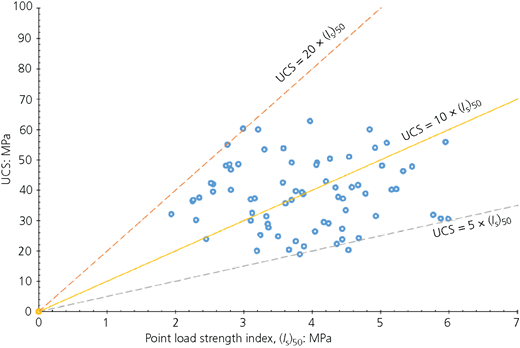
UCS plotted against the index strength by point load test of the limestone rock for the site
UCS plotted against the index strength by point load test of the limestone rock for the site
A preliminary test pile was installed and tested for the detail design of the actual piles. The preliminary test pile showed that the rock parameters that were assumed (mainly the unit skin friction of the limestone) could be further increased. It was increased from 600 to 750 kPa based on the results of the preliminary test pile, provided that it is competent rock. Figure 19 shows the load–settlement curve for an initial test pile. Further, maintained load and PDA tests on the completed piles showed that the design length of the piles and the socket length in the limestone bedrock were adequate to take the loading.
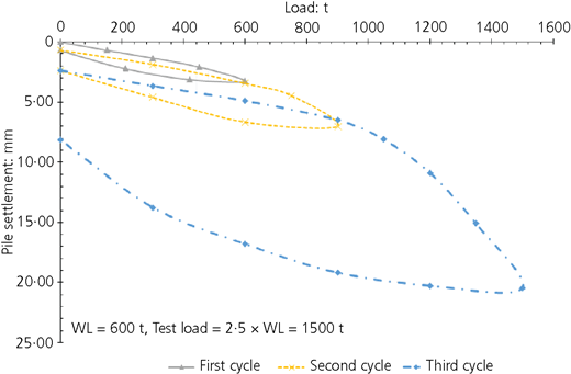
Load-against-settlement plots for cast-in-situ bored piles of 1·2 m dia. for preliminary sacrificial test pile. WL, working load
Load-against-settlement plots for cast-in-situ bored piles of 1·2 m dia. for preliminary sacrificial test pile. WL, working load
Conclusions
From this project, it is clear that interactive design is vital for the success of projects in complex geological conditions. Quality control during construction and performance testing was conducted more frequently compared to other projects. An elaborate project quality plan was also implemented. Thorough site investigations and their interpretations were necessary to define suitable ground treatment or foundation solutions. Potential risks and hazards were identified before the construction started, and mitigation methods or appropriate solutions were adopted. Regarding cost, the use of interactive design resulted in significant savings. Initial designs that used deep foundations were converted to ground improvement solutions once adequate SI results were analysed. Moreover, using interactive design resulted in time saving, since an appropriate solution for each case was identified ahead of construction and rework and wastage were minimised.
Clear and frequent communications between the owner, project manager and geotechnical engineer were instrumental in allowing dynamic modification or change of design to suit actual site conditions. During construction, further investigative works were conducted when the need arose to confirm further assumed design parameters. Such an approach is in congruence with the observational approach and allowed quick modifications without delaying construction progress. Use of such a method also enabled the geotechnical engineer to follow the performance of the design carefully. Strategic placement of instrumentations and their active and consistent monitoring contributed to the overall success of the project within programme and budget.
