
This paper details key aspects of the update of the Construction Industry Research and Information Association’s good practice on embedded retaining walls (C760). The authors of C760 provide an overview of the new guidance on the selection and design of vertical embedded retaining walls that satisfy the requirements of Eurocodes. The guidance also covers temporary and permanent cantilevers, and anchored, single-propped and multi-propped retaining walls that are supported by embedment in soft soils, stiff clays and other competent soils and soft rocks. C760 addresses the technical and construction issues relating to the selection of appropriate wall types and construction sequence to achieve a satisfactory design. It clarifies areas of ambiguity and common misunderstandings when applying the Eurocodes to the design of embedded retaining walls and presents a clear, unambiguous method for the application of the observational method.
Notation
Introduction
An earth-retaining wall is required to withstand forces exerted by a vertical or near-vertical ground surface. An embedded retaining wall is one that penetrates and obtains some lateral support from the ground at its base.
The bending capacity of such a wall typically plays a significant role in the support of the retained material, particularly if it is free-standing. The wall may also be supported by structural members such as props, berms, ground anchors and slabs, and it may form part of a larger structure.
C760 (Gaba et al., 2017) provides guidance on the selection and design of vertical embedded retaining walls in compliance with the principles in the Eurocodes. It covers all types of retaining walls, including sheet pile walls, king post walls, contiguous bored pile walls, secant bored pile walls and diaphragm walls.
It is possible to make economies in embedded retaining walls by selecting an appropriate wall type and support system for the envisaged construction method, construction sequence and long-term use. It is important to adopt a clear, unambiguous design method and to follow appropriate good practice of ground investigation, laboratory and field testing and design analysis, and utilise good-quality case study data. C760 provides guidance on all these points.
Construction Industry Research and Information Association and ground engineering
Whether it is designing and constructing embedded retaining walls for some of the world’s most iconic (and not so iconic) infrastructure or designing and constructing levees to protect vulnerable communities from flooding, Construction Industry Research and Information Association’s (Ciria) good practice guidance documents are used for a variety of construction and civil engineering schemes.
From everyday construction projects to once-in-a-lifetime major infrastructure schemes, enabling practitioners to design, construct and manage better has been the role of Ciria’s research since the inception of the organisation in 1967. The very first research and development work Ciria commissioned was on a series of practical piling guides, leading to the PG Piling series, which became the industry standard for the decades that followed.
Research that Ciria undertakes in the area of ground engineering is steered by the Ciria Ground Engineering Advisory Panel before the wider industry is approached to support its development. Ciria also provides secretariat services to the client-led Geotechnical Asset Owners Forum, which helps position Ciria to identify and develop guidance that meets their particular needs.
Ciria’s ground engineering research is a part of Ciria’s civil engineering infrastructure programme of good practice guidance research, which is now heavily influenced by the ‘digital transformation’ and the profound opportunities afforded to the civil engineering sector through rapid technological advances and innovations in monitoring, testing and modelling of civil engineering infrastructure.
Background to C760
In 1984, Ciria published R104 (Padfield and Mair, 1984). This was quickly adopted by practitioners as the most authoritative document on the subject and was hugely influential.
Although strictly applicable to the design of singly propped or cantilever walls embedded in stiff overconsolidated clay, the principles presented in that guide were applied to a wide range of wall types and soils in the UK and internationally, including multi-propped embedded walls and also non-embedded walls.
Some 20 years later, R104 (Padfield and Mair, 1984) was updated and extended by Ciria C580 (Gaba et al., 2003). C580 applies to the design of temporary and permanent cantilevers and anchored, single and multi-propped retaining walls supported by embedment in stiff clay and other competent soils. Since its publication, C580 has been among the bestselling and most downloaded guides published by Ciria. It has been used nationally and internationally as a design standard for many major projects, past and current.
Although C580 excluded retaining walls embedded in soft clays or weak rock, its principles were applied internationally to walls embedded in such ground conditions. The UK National Annex to Eurocode 7 (EC7) (BS EN 1997-1:2004+A1:2013 (BSI, 2004a) and BS EN 1997-2:2007 (BSI, 2007a)) also references C580 as Non-contradictory Complementary Information. As the principles in EC7 have matured in their application, a revision to C580 was required for Eurocode compliance and to draw together the key lessons learned over recent years. C760 collates the best ideas and experiences available in British practice since C580 was first published and provides clear design guidance compliant with the requirements of the Eurocodes. The document also capitalises on where the Eurocodes allow the designer to exercise innovation.
Overview of C760
Aim and application
C760 provides guidance on the whole process of economic design of embedded retaining walls, bringing together the key aspects of the wall through each stage of the design life cycle. The book brings current guidance on embedded retaining walls up to date, following good practice and being consistent with recent research and current analytical techniques. Part of the intention of the book is to generate discussion which will inform future revisions of Eurocodes, EC7 in particular.
C760 is expanded in breadth from the previous C580 publication to cover ‘less competent’ soils (defined as having undrained shear strength of <40 kPa) and ‘weak rocks’ (unconfined compressive strength of <5 MPa), in addition to more competent soils, which C580 was previously based on. As before, the guidance provided is aimed at geotechnical category 1 and 2 structures, although the principles apply to category 3 structures too.
C760 is written to take the designer systematically through all aspects of embedded retaining wall design, starting from available wall types and construction methodology to discussion of design principles, parameter selection and methods of analysis for both wall and support systems. One significant addition to the previous book is the inclusion of a detailed framework for application of the observational method (OM), either from the start or part way through a project. New guidance on inspection, maintenance and monitoring of a wall during its lifetime is also included, along with a comprehensive update of the ground movement database presented in C580. Although in the book each topic is discussed in its own chapter, it should not be assumed that any of these aspects can be considered in isolation – economic design requires each aspect to be considered systematically by the designer to ensure full integration of the design. This remainder of this section will give a brief overview of the book.
Report structure
Design and construction considerations: chapters 2 and 3
After a short introduction and background to the relevant codes of practice and design standards for embedded retaining wall design, C760 begins by outlining the importance of communication between different interacting roles within a construction project. This includes a brief description of the duties of responsible parties under The Construction, Design and Management Regulations 2015 (HMG, 2015) and highlights the key principles of managing and communicating risks. The philosophy of limit state design is introduced, and different modes of failure are illustrated for consideration. Also in the early part of the book is detailed guidance on selection of the type of wall and the relative merits and disadvantages of each type, assessing factors such as cost, construction methods and tolerances. The report tabulates the advantages and limitations of various wall types (with reference to watertightness, construction, structural and carbon dioxide considerations) and the ‘typical’ and ‘best achievable’ verticality tolerances based on the latest construction practice. Now, to reflect the requirement of many clients for a design which demonstrates savings in both cost and carbon dioxide, the book also includes guidance on the environmental aspects of wall choice. Figure 1 shows an example of such an assessment for a typical piled wall.
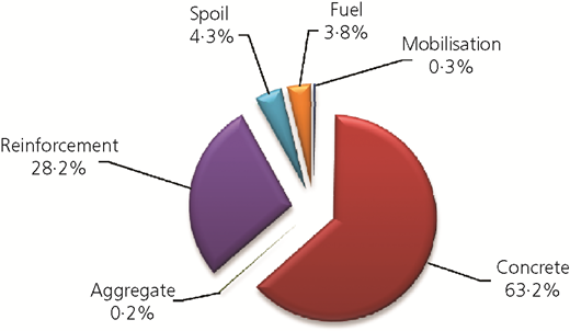
Example of estimated carbon dioxide embedded and emitted for a typical wall project
Example of estimated carbon dioxide embedded and emitted for a typical wall project
Once the wall type has been selected, consideration is given to wall support methods, for both temporary and permanent works, and considerations regarding the construction sequence are introduced with detailed guidance on top-down and bottom-up construction and the drivers for each. It is important for these to be considered early in the design such that appropriate construction methods can be selected and the designer can work to eliminate health and safety risks where possible.
Analysis and parameter selection: chapters 4 and 5
By this point, the wall type and construction method will be developed, and the middle parts of the book focus on selection of parameters for use in design calculations, including soil and groundwater conditions, loads, actions, excavation geometry and partial factors which are applied to account for uncertainty and ensure acceptable deflections. Considerable attention is also given to the method of analysis, with a comparison of different calculation methods presented in the corresponding appendix.
Ground movements: chapter 6
An extensive database of published case history data is presented to help the designer estimate likely ranges of ground movements during both the installation and excavation of the wall. These movements are separated for both soft soils and more competent soils, paying particular consideration to system stiffness. Additionally, the book now considers three-dimensional (3D) effects of ground movements in terms of the relationship between the plane strain ratio and excavation geometry. The dependence of ground movements on aspects such as construction control, workmanship and timing of support installation is described. Chapter 6 also sets out the principles of building damage assessment for cases where the resulting movements are still of such magnitude that they have the potential to cause damage to nearby buildings and third-party assets.
Design of wall, support and life cycle considerations: chapters 7–9
These sections focus on the design of the wall and of temporary support systems. They identify the performance criteria for the wall and the limit states which need to be considered, including demonstrating that these will not be exceeded by adopting one of the design approaches permitted in EC7 – that is, design by calculation, by prescriptive measures or by the OM. A framework for the OM is provided for the first time in chapter 7. Finally, consideration is given to the maintenance, inspection and monitoring implications of wall design, throughout the whole life cycle of the structure.
Key sections and conclusions of C760
The following sections cover four important aspects of the book in more detail. These are the use of nomograms to determine pile spacing and interlock, structural design, a new framework for the OM and a detailed comparison of methods of geotechnical analysis. All of these are chosen as they represent areas where considerable changes have been made since C580.
Nomograms for determining pile spacing and interlock
The verticality of an embedded wall is linked with the piling technique used and is a function of a variety of factors, including driver experience, depth of excavation, speed of construction, drilling tool stiffness, ground conditions, use of casing, provision of a guide wall and drilling/excavation equipment.
The achieved verticality of an embedded retaining wall is also linked with the maximum depth over which the interlock for water cut-off can be maintained between primary and secondary secant hard-firm piles. This link is presented in C760 with the aid of a new graphical method for the selection of the cut between primary and secondary piles and pile spacing to achieve the required interlock for water cut-off. Figure 2 illustrates the proposed method for establishing the required spacing in hard-firm secant wall piles constructed using the continuous flight auger (CFA) piling method (a similar nomogram is available in C760 for secant wall piles). This new method is summarised as the following five simple steps.
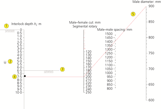
Determining minimum cut and spacing required for hard-firm piles constructed with CFA piling rigs (verticality tolerance 1:100, positional tolerance ±25 mm) (reproduced from Figure A3.12 of C760 (Gaba et al., 2017))
Determining minimum cut and spacing required for hard-firm piles constructed with CFA piling rigs (verticality tolerance 1:100, positional tolerance ±25 mm) (reproduced from Figure A3.12 of C760 (Gaba et al., 2017))
Step 1 is drawing the relevant geological section from the design ground model. Step 2 is identifying the design groundwater table level. Step 3 involves drawing a line that signifies the maximum anticipated excavation at this section. Step 4 is establishing the level where the interlock for water cut-off is required and drawing a perpendicular line to the interlock depth axis to find the required cut between primary and secondary piles. This level signifies where there is (theoretically) zero interlock between primary and secondary piles if the positional and verticality tolerances are considered in the worst-case orientation for both piles. The final step is connecting the point showing the value of the required cut to the point showing the proposed secondary pile diameter. The line will intersect the secondary-pile-to-secondary-pile spacing axis showing the required spacing to achieve the required interlock.
The report also lists the typical range of pile diameters that are available with CFA, cased CFA and segmental casing rotary rigs forming a secant piled wall. Where a segmental cased rotary system is used to construct a secant wall, the cased section would typically provide a minimum of 1 m seal into a low-permeability layer or 1 m below the formation level, whichever is the lower. Where a segmental cased wall pile is constructed, the designer must consider that the diameter of the secondary pile below the cased section would correspond to the drilling tool size and so would be of smaller diameter. To this end, the range of typical casing sizes and drilling tools presented in C760 can assist the designer in selecting the appropriate pile diameter for the most efficient geotechnical and structural design of the wall. The book also includes other useful guidance, such as guide wall detailing, advice on minimum and maximum cuts in secant hard-firm walls, and construction considerations for the feasibility of diaphragm walls.
Structural design
The structural design section refers to the latest Eurocodes that are relevant to embedded retaining walls, namely EC2-1 for reinforced concrete (BSI, 2004b), EC3-1 for structural steelwork (BSI, 2005) and EC3-5 for steel piling (BSI, 2007b). The book highlights the need to consider the loads generated by the temporary and permanent construction stages in addition to the installation method. For driven steel sheet piling, it provides a concise summary of the durability requirements and the basic definitions of the design moment resistance of steel sections as per EC3-5 recommendations. Where the wall piles are meant to carry vertical loads from the superstructure and/or basement slab levels, C760 makes recommendations regarding the format of Eurocode actions for clarity and efficiency in the design (see the article by Selemetas and Bell (2014)).
For reinforced-concrete sections, significant cost savings are possible if a pragmatic approach is taken to crack width control. Before making an assessment of what is considered to be an acceptable crack width, the designer should consider the exposure class and corrosion conditions at a given crack location, the ground conditions (effect of permeability) and the bending moment distribution (whether the section will be in compression or tension at that section). For an economic design outcome, the designer should consider crack widths as a function of construction time as well as depth – for example, it may be acceptable to have a larger crack width during the transient design situation (temporary construction case), but then have a tighter limit in the long term. The book also highlights that the location and orientation of a crack is more important than its size. To assist the designer in the assessment of crack width control criteria, a simple assessment framework is presented in chapter 7 of C760. This framework is illustrated in Figure 3, where four distinctive zones are identified with reference to the significance of cracking on the corrosion of reinforcement in a reinforced-concrete embedded wall: zone 1 (wet, no risk of corrosion), zone 2 (wet and dry, most prone to corrosion), zone 3 (dry, corrosion may occur when the ground is moist from rain) and zone 4 (atmospheric, risk of corrosion depends on waterproofing provisions). Where the conditions are conducive to corrosion and crack width control criteria apply, a simple assessment method in EC2 without direct calculation is referred to. Where crack width calculations are required, BS EN 1992-1-1:2004+A1:2014 (BSI, 2004b) and PD 6687-1:2010 (BSI, 2010a) should be referred to. This method uses the refined model for the calculation of crack widths for circular sections and irregular bar layouts (clause 2.22 of PD 6687-1:2010). Crack width calculations should be based on the serviceability limit state (SLS) calculations assuming the quasi-permanent combination of actions – that is, unfactored permanent actions and a combination of variable actions reduced as per clause 6.5.3(2c) of BS EN 1990:2002+A1:2005 (BSI, 2002).
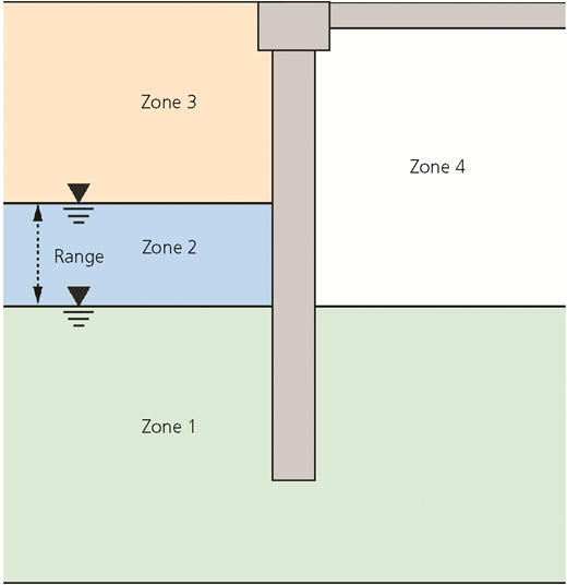
Corrosion zones for the assessment of crack width control criteria (reproduced after Figure 7.14 of C760 ((Gaba et al., 2017))
Corrosion zones for the assessment of crack width control criteria (reproduced after Figure 7.14 of C760 ((Gaba et al., 2017))
C760 also provides practical considerations for the design of lap lengths, with reference to the latest execution standards requirements of BS EN 1536:2010+A1:2015 (BSI, 2010b) and BS EN 1538:2010+A1:2015 (BSI, 2010c).
The observational method
Background
Another area where C760 has received considerable update is in defining a new framework for the OM. The OM is described in Ciria R185 (Nicholson et al., 1999) as a continuous, managed, integrated process of design, construction control, monitoring and review that enables previously defined modifications to be incorporated during or after construction as appropriate. The objective is to achieve greater overall economy without compromising safety. The OM can be adopted at project inception or during construction, and when applied correctly, it can offer economic and programme savings as well as a more rigorous approach to risk management. Although implementation of the OM will almost certainly require extra investment in analysis, design and monitoring, these costs are offset by the potential savings in construction costs. These potential savings have been demonstrated at the Tottenham Court Road station during the Crossrail project, where the value-engineering redesign of the temporary propping using the OM and the successful excavation of the western ticket hall delivered savings of around £5 million and 6 weeks on the programme (St. John et al., 2017).
The OM was first formalised for geotechnical engineering design by Peck in his Rankine lecture in 1969 (Peck, 1969). Peck (1969) identified two approaches: ‘ab initio’, where the implementation of the OM was planned from the beginning of construction, and ‘best way out’, where the OM was implemented to prevent SLSs or ultimate limit states (ULSs) from occurring. The next significant development of the OM followed the publication of Ciria R185 (Nicholson et al., 1999), where more information was provided on implementing the OM ab initio, including the choice of parameters, designing instrumentation and monitoring and setting of trigger limits.
The approach to implementing the OM ab initio proposed by Nicholson et al. (1999) had a significant difference from that of Peck (1969); Nicholson et al. (1999) proposed that the base design should be undertaken with characteristic parameters with the opportunity to make modifications based on most probable assumptions. Peck (1969) proposed that the base design be based on most probable assumptions with pre-planned contingencies if the behaviour tended towards characteristic. The different approaches to ab initio OM have significant impacts on the potential savings that can be realised in the cost of materials through the application of the OM. The savings can only be maximised if the Peck approach is followed as, once a retaining wall is installed, its length or reinforcement cannot be changed.
New C760 framework for OM
Despite the clear benefits in terms of economy, programme and the management of risk, the OM has not gained widespread acceptance in geotechnical engineering. The reason for this is not clear. It may be due to the misconception that it increases project risk, rather than providing a rigorous framework for its management, or perhaps the extra investment in design and analysis at an early stage of a project is unattractive to clients.
Through the publication of C760, the authors hope to reinvigorate the use of the OM by introducing a new framework for its implementation. In addition to the existing ab initio (‘from the start’) approach, where the implementation of the OM is planned before construction, the proposed framework introduces a new category referred to as ipso tempore (‘in the moment’), where the OM is introduced during construction. Each category is divided into two subcategories, resulting in four approaches (referred to as A, B, C and D), which are described as follows and summarised in Table 1.
Summary of the OM framework as defined in C760 (Table 7.2 of Gaba et al. (2017))
| OM approach | Ab initio (from the start) | Ipso tempore (in the moment) | ||
|---|---|---|---|---|
| A – optimistic (Peck, 1969) | B – cautious (Ciria R185 (Nicholson et al., 1999)) | C – proactive | D – reactive (Peck, 1969) | |
| When does OM design work start? | Before wall construction | After wall construction | ||
| Starting design assumptions | Most probable parameters | Characteristic parameters | Necessary, from back-analysis of initial stages | |
| Back-analysis requirements | Necessary, with reliable case study data | Preferred | Use initial construction stages | |
| Design objectives | Optimise wall depth/strength support | Optimise wall support | Reduce wall support | Increase wall support |
| Alternative design plans | Use contingency plan | Use modification plan | Introduce modification plan | Introduce contingency plan |
APPROACH A: AB INITIO OPTIMISTICALLY PROACTIVE
This approach is equivalent to ab initio as defined by Peck (1969) in which the base design and construction sequence is undertaken using most probable parameters, but with a pre-planned contingency based on characteristic assumptions.
APPROACH B: AB INITIO CAUTIOUSLY PROACTIVE
This approach is equivalent to ab initio as defined by Nicholson et al. (1999) in which the base design and construction sequence is undertaken using characteristic assumptions but with the potential for pre-planned modifications which are based on the most probable behaviour.
APPROACH C: IPSO TEMPORE PROACTIVE TO MAKE MODIFICATIONS
This approach is previously undefined, but, in the authors’ experience, it is probably the most common application of the OM. The original design was undertaken using a standard ‘design-by-calculation’ approach with characteristic parameters. During the construction works, wall movements or some other observation leads the team to make a proactive decision to adopt the OM to make improvements on the future construction stages in order to achieve programme and/or cost savings.
APPROACH D: IPSO TEMPORE REACTIVE TO MAKE CORRECTIONS
This approach is equivalent to the ‘best way out’ identified by Peck (1969). As with approach C, the original design was undertaken using standard ‘design by calculation’; however, through some observations or monitoring results, the construction is not going according to plan and additional measures are required to prevent an SLS or ULS failure.
As noted in Table 1, savings in materials and programme can be maximised only with the adoption of approach A, whereas only programme savings and limited material costs can be saved through approach B. The choice between approaches A and B will be predominantly dictated by the designers’ and contractors’ familiarity with the ground conditions, although other considerations will include the availability of documented case histories, the contractual and cultural environment and the individual’s appetite for risk.
The following requirements are central to the successful implementation the OM.
The designer, the contractor and, if required, the checking organisation have the analytical tools to make reliable predictions and, when required, rapid back-analysis of data.
The scoping and specification of instrumentation and monitoring are critical as the whole process relies on reliable data being available to the designers.
The team must be prepared to follow the planned contingencies should the behaviour tend towards characteristic. It is tempting to think that the potential savings identified in the most probable design are guaranteed.
In summary, by providing a clear framework for the application of the OM to the design of embedded retaining walls, including recommendations for setting trigger limits and the design of instrumentation and monitoring, the authors of C760 hope to reinvigorate the use of the OM in geotechnical engineering, particularly in large infrastructure projects where the scale of the structures and the high calibre of the parties involved should yield significant savings for the clients and ultimately the country.
Methods of geotechnical analysis
The fourth aspect which has received significant update is the guidance on geotechnical analysis. Since the publication of C580 in 2003, the availability of computing power for geotechnical analysis has continued to increase such that fully 3D finite-element or finite-difference analysis replicating complex geometry and ground conditions is now feasible. However, it is used mainly in connection with major projects, and accurately capturing all relevant aspects of soil behaviour remains a challenge, in terms of both constitutive models and parameters.
Subgrade reaction or pseudo-finite-element-based programs (such as Wallap and Frew) remain popular, as they model soil–structure interaction effects and pre-failure behaviour for designing against SLSs in a reasonably realistic yet achievable way. These programs also facilitate limit equilibrium analysis of simple embedded cantilever walls (unpropped or propped near the crest) for ULS calculations (EC7 Design Approach 1 Combination 2 (DA1C2) in which partial factors greater than unity are applied to the soil strength parameters) to determine required embedment depths.
Finite-element programs can be used to carry out DA1C2 ULS analyses, either
with the reduced soil strength applied throughout the whole analysis (strategy 1 as defined by Simpson (2012))
by starting and continuing the analysis to each key stage with the full soil strength and then reducing the soil strength by the required partial factor to investigate the effect on each stage separately (strategy 2 as defined by Simpson (2012)).
Several authors have investigated the effect of the choice of strategy (Bauduin et al., 2000; Schweiger, 2005; Simpson and Driscoll, 1998; Simpson and Hocombe, 2010; Simpson and Yazdchi, 2003), without drawing consistent conclusions. At present, either approach is acceptable, although there is an emerging preference towards strategy 2 as it can lead to the calculation of larger bending moments in multi-propped walls.
In appendix A4 of C760, the effect of the method of analysis used (limit equilibrium, simple soil–structure interaction and finite element) is investigated with respect to four simple embedded walls, cantilever and propped near the crest, in terms of effective and total stresses. The comparative analyses showed the following.
Where there is little or no stress redistribution – for example, unpropped cantilever walls – simple limit equilibrium calculations and soil–structure interaction analyses (subgrade reaction/pseudo-finite element and finite-element/finite-difference methods) gave broadly similar wall embedment depths. Patterns of wall bending moment and shear force were broadly similar. Maximum bending moments varied by ∼20%, and maximum shear forces by twice that.
For propped or anchored walls where stress redistribution may occur, limit equilibrium calculations tended to result in slightly longer walls than soil–structure interaction analyses. Again, the patterns of bending moment and shear force distribution within the wall were broadly similar. However, the maximum bending moments calculated using soil–structure interaction analyses were generally (but not always) smaller than those obtained from a simple limit equilibrium calculation. The use of soil–structure interaction analyses may therefore result in cost savings, depending on project- and site-specific details.
Prop loads calculated using limit equilibrium methods in which active pressures were assumed to apply all the way down the retained side of the wall, including above the prop, were generally smaller than those obtained from soil–structure interaction analyses. This is probably a result of the calculation of enhanced lateral stresses behind the wall in the region of the prop in soil–structure interaction analyses, as the differences were generally much smaller when passive pressures behind the wall above the prop level were assumed (taking account of the relative reversal in the direction of soil/wall friction or adhesion). Thus, prop loads obtained from limit equilibrium calculations in which active conditions are assumed behind the wall above and below the prop may be underestimated and should be treated with caution in design.
Calculated bending moments and shear forces are very sensitive to relatively small changes in pressures around the wall. They may also be influenced by node spacings in beam on springs and pseudo-finite-element models and mesh details in finite-element and finite-difference models. The designer should carry out sensitivity checks on the effects of such variations in the models adopted.
For the simple example geometries considered, structural effects (prop loads, shear forces and bending moments) calculated using the DA1C2 partial factors were generally greater than those calculated using DA1C1 for the effective stress analyses. For the total stress analyses, the reverse was the case (i.e. effects of actions calculated using the DA1C1 partial factors were greater than those using DA1C2). For both types of analysis, effects of actions calculated for the SLS were generally less than those for either the DA1C1 or DA1C2 ULS.
In summary, it is prudent to carry out some simple calculations as a check on more advanced soil–structure interaction methods. Limit equilibrium analyses can be used with confidence to calculate ULSs for unpropped embedded cantilever retaining walls. Walls propped or anchored at the top offer opportunities for stress redistribution away from the simple linear increase with depth assumed in a limit equilibrium calculation. In such circumstances, a shorter wall, smaller calculated wall bending moments and possibly greater calculated prop or anchor loads will be obtained from soil–structure interaction analyses than from limit equilibrium calculations. Prop or anchor loads obtained from limit equilibrium calculations in which active conditions are assumed behind the wall above the prop may be underestimated and should be treated with caution.
Stress distributions under working conditions are likely to differ significantly from collapse limit equilibrium distributions for walls other than unpropped embedded cantilevers. A soil–structure interaction analysis for SLS calculations may then lead to a more economical design. Guidance on the selection of structural properties for walls and props for use in this type of analysis is provided in C760. The wall flexural stiffness, EI, should be appropriate for each construction stage and in the long term. For reinforced-concrete walls, it is often appropriate to adopt 0·7E 0 I and 0·5E 0 I during the construction and long-term stages, respectively, where E 0 is the uncracked short-term Young’s modulus of concrete (typically E 0 = 28 GPa) and I is the second moment of area of the reinforced-concrete section.
The document also summarises recent field data and finite-element analysis relating to wall installation effects. Wall installation might be expected to cause a 10% reduction in the in situ lateral earth pressure coefficient for bored pile walls and 20% for diaphragm walls installed in overconsolidated clays. In a simple elastic soil–structure interaction analysis (in which the pre-failure deformation behaviour of the soil is assumed to be linear and no allowance is made for the effect of recent stress history on the soil stiffness), a pre-excavation lateral earth pressure coefficient of unity is likely to give reasonably realistic bending moments and prop loads for walls embedded in stiff overconsolidated clays. If K 0 < 1, it is suggested that the pre-excavation lateral earth pressure coefficient be taken as K 0 (i.e. wall installation does not change the in situ value).
If the soil is represented using a constitutive model that allows for the effect of recent stress history on soil stiffness (i.e. it assigns a higher stiffness to the soil behind the wall than that in front), it is recommended that, in a heavily overconsolidated deposit, a reduction in in situ lateral earth pressure coefficient of 10–20% be applied or that wall installation be modelled explicitly. If 0·5 < K 0 < 1, it is suggested that the pre-excavation value of lateral earth pressure coefficient be taken as K 0. If K 0 < 0·5, it is suggested that the pre-excavation value be set to 0·5 to represent a possible increase during installation to approximately the bentonite support pressure.
For embedded walls in stiff clay, field evidence indicates that the long-term lateral effective stresses remain largely unchanged from those at the end of the construction period, with changes in lateral stress being largely associated with changes in pore water pressure (Richards et al., 2006, 2007).
Latest Ciria research and developments following the publication of C760
Following the publication of C760, Guidance on Embedded Retaining Wall Design, Ciria has published C775, Rock Netting Systems – Design, Installation and Whole Life Management (Koe et al., 2018), and started the projects ‘Advanced numerical modelling in geotechnical engineering’ and ‘Grouted anchors and soil nails – condition appraisal and remedial treatment’.
A series of collaborative events and workshops in 2018 looked at strategies for managing engineered and natural slopes with the aim of identifying the required research outputs to deliver industry benefits. It was concluded that Ciria should develop good practice guidance on assessing natural slope risks and engineering with geosynthetics.
C774, Grouting for Reservoir Dams (Hughes et al., 2018) was published in autumn 2018, with the findings of a research project on asset deterioration modelling of civil engineering infrastructure following it later in the year. Ciria is also planning the research project ‘Construction impact – prediction, assessment and control of damage from ground movements’.
These projects, proposals and events all fall within Ciria’s civil engineering infrastructure programme of good practice guidance research. Ciria continues to provide secretariat services for the Geotechnical Asset Owners Forum and is supported by its members and the Ground Engineering Advisory Panel.
Conclusions
The authors of C760 strived to include the many lessons learned since C580 was published in 2003 as well as providing Eurocode (EC7, EC2 and EC3)-compliant guidance and generally bringing the document more up to date with current good practice and presenting more recent case study data. Like its predecessor, it is anticipated that C760 will be adopted nationally and internationally. It is hoped that the adoption of the new OM framework will deliver savings in programme and cost in future projects.
The importance of updating this guidance was made clear by the extensive support it received from Ciria members and the ground engineering industry. To conclude, C760 will provide good practice guidance for the design of embedded retaining walls for the foreseeable future and until the next generation of Eurocodes.
Acknowledgements
Ciria and the authors of C760 would like to acknowledge the project funders not only for providing financing for the project but also for their substantial in-kind contribution in the production and dissemination of the guide, the project steering group and other contributors, all of whom gave their time generously. The full list of funders, project steering group members, contributors and other contributors is given in the guide.
