

The Bahce–Nurdag tunnel, which is the longest railway tunnel in Turkey with approximately 10 km was planned as two tubes. During the excavation of the second tube starting from the Nurdag portal, the tunnel-boring machine (TBM) jammed at 1267 m of the excavation. The second tube was abandoned due to TBM jamming, and it was decided to build a third tube. For this construction, additional portal and tunnel excavations were needed. These excavations resulted in additional stresses. Moreover, the project was constructed in a highly seismically active region. For this purpose, the tunnel portal section was investigated numerically by finite-element analysis. Considering the results obtained from the three-dimensional (3D) numerical analysis, the existing portal was enlarged and excavation of the third tube was started. Currently, the portal construction was successfully completed, and the third tube was excavated for approximately 2200 m with the TBM. It was concluded that the suggested methodology with the excavation and support systems was found satisfactory when the analysis results were compared with in situ conditions. This study suggests that multiple tunnels and large portals to be constructed in highly seismically active regions be simulated by 3D numerical analysis for successful construction.
Notation
- c
cohesion
- D
disturbance factor
- E
Young’s modulus
- En
interslice normal force
- f(x)
prescribed function that dictates the variation of the X/E n ratio along the slip surface
- g
gravitational acceleration
- L
length
- mi
intact rock parameter
- tan(Φ)
slope of the failure envelope
- X
interslice shear force
- γ
unit weight
- λ
constant scale factor
- ν
Poisson’s ratio
- σ
normal stress
- τ
shear strength
- Φ
friction angle
Introduction
Tunnelling in dense urban areas frequently results in over-crossing or bypassing the existing tunnels (Liang et al., 2016). In addition, highway and railway tunnels are often designed as twin-tube tunnels (Aygar and Gokceoglu, 2021a). In this case, the tunnels are assessed as multiple openings. Due to their potential adverse effects on each other, some researchers have investigated closely spaced multiple openings. Chu et al. (2007) performed model tests of twin circular tunnels in homogeneous material, two-layered formations and three-layered formations, while Gue et al. (2017) developed approximate three-dimensional (3D) tunnelling simulations in clay using centrifuge modelling techniques. Gue et al. (2017) mentioned that the results were in good agreement with field data obtained by using various state-of-the-art instrumentation systems.
A shortlist including case studies of tunnel–tunnel interactions in London was published by Avgerinos et al. (2017). Li et al. (2020) published an important case study of closely spaced triple tunnels with large sections in Beijing, China. Boonyarak and Ng (2015) emphasised that the influence of construction sequence on crossing–tunnel interaction is complex, and they performed two pairs of 3D centrifuge tests to investigate the effects of construction sequence on crossing–tunnel interaction.
In the design of tunnels, site selection and the investigation of the risk zones along a tunnel and/or other underground structures is so important due to economic feasibility. Engineering constructions in such regions confront a series of problems related to tectonic activity directly or indirectly, and many tunnelling projects had to be constructed under adverse geological conditions (Aygar and Gokceoglu, 2020, 2021b; Komu et al., 2020; Ozyurek et al., 2021). Consequently, it is possible to encounter problems during excavation and support operations in tunnels. During tunnel excavations, one of the most disappointing results can be tunnel-boring machine (TBM) jamming. All types of weathered rocks, shear zones or faults present in the rock mass and high groundwater pressure may cause such a problem (Hasanpour et al., 2020; Xu et al., 2021).
In Turkey, there are two important fault zones called the North Anatolian Fault Zone (NAFZ) and the East Anatolian Fault Zone (EAFZ), which can produce earthquakes. Consequently, the presence of weak zones and fault zones is inevitable in tunnel projects in Turkey. Thus, it is almost impossible to avoid problematic areas, such as weak, weathered and crushed zones and active faults.
In this study, the TBM jamming problems encountered in a railway tunnel excavation in the south-eastern Anatolia region of Turkey, where the EAFZ affects the geological characteristics of the area, are described and the 3D simulation of the tunnel portal of the triple-tunnel system is presented. Based on the numerical simulations of the triple-tunnel excavation, the mechanism and the slope design concept of the portal are discussed. When considering the project and geological characteristics of the area, this case study is an almost unique case for tunnelling, because two tube tunnels were planned and constructed at the beginning of the project. However, due to the TBM jamming, the project was revised substantially. This revision resulted in serious additional excavations such as third tube tunnel and portal enlargement. These extra construction processes make the study extremely important and interesting for future tunnelling works and scientific studies. Besides, to the best of the authors’ knowledge, a similar study was not encountered in the literature.
Project description
The study area is in the Nurdag District of Gaziantep Province, which is south-east of Turkey (Figure 1). Among the T1 and T2 tunnels planned to be excavated within the scope of the Bahce–Nurdag Fevzipasa Variant project, which is being built by the State Railways of the Republic of Turkey, the T2 tunnel was completed. The tunnels are parallel to each other and are the longest railway tunnels with an approximate length of 10 km in Turkey. The tunnel excavation process has been projected to start at the Nurdag portal and to be finished at the Bahce portal by using the TBM tunnelling method. Due to the presence of landslides and debris material in the portal section on the Bahce side, it was planned to open a certain section with the New Austrian tunnelling method (NATM) at the Nurdag portal even though it is in the EAFZ area. Tunnel excavations were started with NATM due to the crushed and weak zones as the result of the tectonic activities of the EAFZ and the high groundwater pressures. Therefore, crushed and weak zones and high groundwater pressures were encountered. A total of 560 m NATM excavations and support systems were completed in the T1 tunnel and 590 m in the T2 tunnel. While these processes are continuing, on the other hand, the processes of bringing the TBMs to the site and making them ready for excavation have been continued and advantages on the project time have been gained. This plan was successfully implemented in the first tube and the T2 tunnel and is successfully completed. However, the excavation in the second tube (T1 tunnel) was stopped frequently, and finally, when the excavation 1267 m was reached, the TBM totally jammed. This means that only a little more than 10% of the tunnel had been excavated. On the other hand, the existing TBM was not able to excavate the 8 km part of the tunnel.
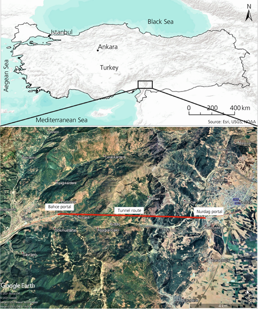
Location maps of the Bahce–Nurdag tunnel. Bottom map © 2021 Basarsoft. © Google. Image © 2021 Maxar Technologies. Image © 2021 CNES/Airbus
Location maps of the Bahce–Nurdag tunnel. Bottom map © 2021 Basarsoft. © Google. Image © 2021 Maxar Technologies. Image © 2021 CNES/Airbus
TBMs are a very suitable option for long tunnels where additional excavation faces cannot be excavated. However, TBMs cannot go back as a necessity brought by the design. To put it more clearly, while a TBM can be removed from the tunnel when it becomes inoperable at any point of the tunnel, it is impossible to replace it with another TBM of the same diameter without making any changes in the excavated tunnel. TBM changes can be performed only in the following ways.
In a tunnel that has been excavated, the segments are completely removed, and the new TBM moves forward by constructing the segment again, which is not a feasible method since disassembling the segments will cause a collapse in the tunnel.
If possible, preserving the segments already built, the tunnel diameter for the section to be excavated is reduced as much as the segment thickness and, a smaller-diameter TBM suitable with this value is continued. However, when the tunnel is excavated for the railway, the application of such a method does not seem possible since tunnel excavation is determined at optimum values in accordance with needs.
In case that the tunnel is shallow, opening the shaft and placing a new TBM is a method that can be applied. However, opening a shaft of this size and depth in the current situation will be quite costly and take an extremely long time. This method, which seems technically possible, will not be a logical engineering solution when evaluated in terms of time and costs.
Constructing an approach tunnel can be considered another option. However, there is no option for an approach tunnel that should be very short compared with 1267 m excavated under current site conditions. Therefore, such an option is not an engineering approach.
The other method of preserving the existing tunnel is to enter from the Bahce side of the tunnel and move the TBM in the direction of Nurdag to meet at the excavated section. However, there is a landslide at the portal of the Bahce and debris material in the rest. Therefore, this section must be excavated with NATM. As a matter of fact, this was experienced during the excavations of the T2 tunnel, shortly after the TBM reached to debris material, a serious failure occurred, and the failure reached the surface. Therefore, in this section, first, a tunnel will be opened with approximately 600 m NATM. Then, the TBM will enter the tunnel, which corresponds to a considerable waste of time. In principle, if there is groundwater where long tunnels are built, the slope should be upwards in the direction of the progress of the TBM. Otherwise, the TBM cannot work, and the tunnel may be lost depending on the length and amount of groundwater. If the TBM enters from Bahce, the slope is downwards in the parts where it approaches Nurdag and the area with high groundwater potential will be reached. Moreover, these areas are also exceptionally long distances from the Bahce portal. Therefore, advancing the TBM from Bahce has the potential to cause even greater losses. As a result, this method also carries great problems that should not be taken.
Considering the impossibilities and/or extreme difficulties of the first five options given above, the last option was the alternative to excavate the T1 tunnel again by abandoning the excavated 1267 m section and excavating from the Nurdag portal. In particular, by successfully excavating the T2 tunnel and using the experience gained here, it is possible to open the new T1 tunnel more economically, quickly and successfully.
As a result, alternative (f), which seems to be the most suitable in terms of engineering solution among the six alternatives, is detailed and presented in this study. In other words, in solution proposal (f), if a new tunnel is opened approximately 8 m from T1 (the existing tunnel to be abandoned) by expanding the existing portal, some changes are required in the route. Numerical analyses have been carried out for the situation that may appear in the case of expanding the portal and opening a third tunnel.
Geological and geotechnical conditions
The study area is located in the EAFZ. The EAFZ is approximately 500 km long in a north-east–south-west direction and forms the boundary of the Arabian and Anatolian Plates (Figures 2(a) and 2(b)). The measured movement velocities of the plates are 6–10 mm/year, and these movements cause serious stress accumulation on the faults.
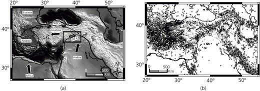
(a) Position of the Anatolian and Arabian Plates and the EAFZ (NAFZ); (b) relative movements of the plates and the earthquakes that have occurred (Bulut et al., 2012)
(a) Position of the Anatolian and Arabian Plates and the EAFZ (NAFZ); (b) relative movements of the plates and the earthquakes that have occurred (Bulut et al., 2012)
The Anatolian Plate is bounded in the north by the NAFZ. Since 1939, 11 devastating earthquakes have occurred on the NAFZ. However, when compared with the NAFZ, although it has produced very large earthquakes in the historical period (Figure 3), the EAFZ has been relatively quiet in the past century. Therefore, these states point that there are remarkable stress accumulations on the EAFZ segments. In a study carried out by Nalbant et al. (2002), the stress change on the EAFZ since 1822 has been investigated and it has been determined that there is a high stress accumulation in the Kahramanmaras (KM) region, which is very close to the project site, as seen in Figure 4.
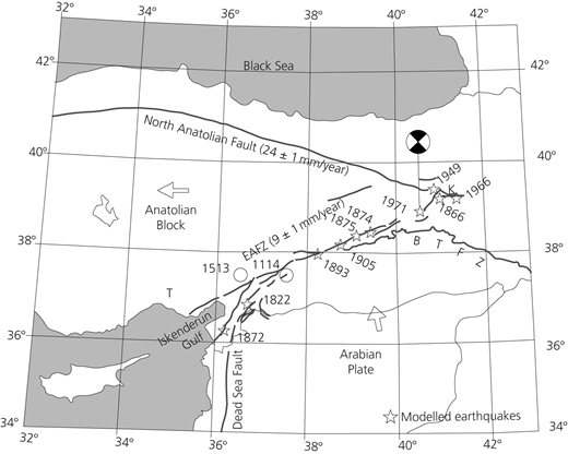
Historical earthquakes on the EAFZ (Nalbant et al., 2002)
Historical earthquakes on the EAFZ (Nalbant et al., 2002)
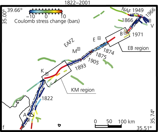
Stress accumulations on EAFZ segments (the KM region is Kahramanmaras) (Nalbant et al., 2002)
Stress accumulations on EAFZ segments (the KM region is Kahramanmaras) (Nalbant et al., 2002)
Nalbant et al. (2002) state that there is limited information about the seismic activity of the KM Zone, but if this segment is broken at once, an earthquake greater than 7.3 will occur. Historical documents estimate that the intensity of the earthquake that occurred in this region in 1114 was 7.8 or greater. The earthquake, which occurred on this fault in 1513 and is estimated to be 7.4 in magnitude, caused serious damage in Tarsus and Malatya and was felt in Egypt. As a result, the region in which the project site is located has been continuously loaded in the last 200 years and the stresses on this fault have reached the level of 20 bar in places. Also, considering the plate movements, if the segment in the KM region breaks in one go, it should be expected that an earthquake greater than 7.3 and a displacement of more than 5 m will occur.
In this study, the exit portal of the tunnel passes through the Jurassic–Cretaceous aged Karadag Limestone, which covers wholly or partially dolomitic limestone and rarely calcareous mudstone, siltstone or shale interlayers (Figure 5). The EAFZ limits the east of Karadag Limestone, which determines the general geology of the area in the study area (Figure 6). In this context, to create a generalised geological profile, considering the proximity of the study area to the deformation zone, two drillings were carried out and the generalised geological profile was obtained. SK-19 of 120 m depth is located in the west–north-west of the exit portal, and SK-23 with 30 m depth is located at the Nurdag side of the exit portal. The lithological units were determined as slightly to moderately weathered and medium to very weak strength with weak rock quality designation. The depth of the groundwater table is 57 and 7 m below the surface according to the borehole data of SK-19 and SK-23, respectively. The geological cross-section of the tunnel portal is shown in Figure 7.
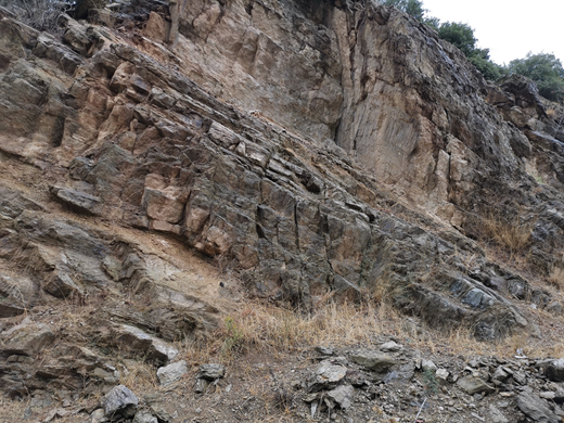
Limestone–shale alternation (Adana–Gaziantep State Road)
Limestone–shale alternation (Adana–Gaziantep State Road)
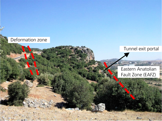
View from the tunnel exit portal section (Fugro Sial, 2014)
View from the tunnel exit portal section (Fugro Sial, 2014)
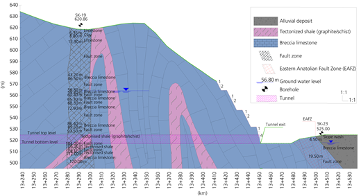
Geological cross-section of the tunnels exit portal on the Nurdag side (Fugro Sial, 2014)
Geological cross-section of the tunnels exit portal on the Nurdag side (Fugro Sial, 2014)
Geotechnical parameters were determined using RocLab according to the laboratory results, uniaxial compressive strength (UCS), rock mass classification systems such as rock mass rating, geological strength index (GSI) and Hoek–Brown criteria and field observations. The geotechnical parameters of the units situated at the portal of Nurdag are given in Table 1. These parameters are used in the Midas GTS NX 3D software program for the 3D analysis of the tunnel portal.
Geotechnical parameters of the units
| Geological units | UCS: MPa | GSI | mi | D | Unit weight, γ: kN/m3 | Cohesion, c: kPa | Friction angle, Φ: ° | Young’s modulus, E: MPa | Poisson’s ratio, ν |
|---|---|---|---|---|---|---|---|---|---|
| Limestone | 15.0 | 35 | 9 | 0 | 26 | 112 | 45.44 | 730.00 | 0.30 |
| Fault zone rock mass | 54.0 | 30 | 9 | 0.7 | 24 | 190 | 33.14 | 485.00 | 0.20 |
| Tectonised shale | 36.1 | 30 | 9 | 0.7 | 22 | 249 | 25.15 | 230.00 | 0.30 |
| Breccia limestone | 60.0 | 39 | 9 | 0 | 26 | 689 | 42.33 | 960.00 | 0.30 |
The triple-tunnel system
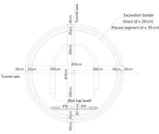
In the beginning, two tube tunnels were planned (Figure 8(a)). However, due to NATM jamming, the portal was enlarged and a new T1 tube was started to have excavated (Figure 8(b)). The new tunnel was planned to be built next to the right (abandoned) tube of the Bahce–Nurdag tunnel, which was under construction by the TBM method. The TBM tunnel section is given in Figure 9. Therefore, the portal structure had to be enlarged from the right side of the tube shown in Figure 10. Hence, it became necessary to enlarge the existing portal and revise the existing slopes.
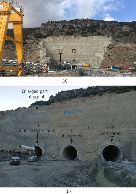
(a) Beginning stage; (b) new construction stage
(a) Beginning stage; (b) new construction stage
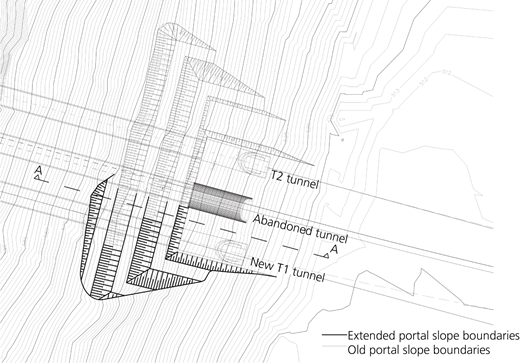
General layout plan of the Nurdag exit portal
General layout plan of the Nurdag exit portal
Tunnels excavated close to each other may affect each other due to the additional stresses that they create. In this section, there are two tunnels that have been excavated and supported without failure. Tunnels that have more than one opening and affect each other in terms of stress and deformation are defined as multiple openings. Thereby, extra measures should be taken to ensure that this interaction is as little as possible. There are two tunnels (T1 and T2) excavated before, leaving 8 m between them. In the previous analyses, it was understood that the 8 m heel left in between was sufficient, and an approximately 1250 m double-tube tunnel was completed. For this reason, it was recommended to open the third tube by leaving an 8 m heel.
Currently, the tunnel exit portal front slope and side slopes have been designed as 1H/4V (horizontal/vertical) and 1H/2V, considering the topographic conditions and excavation distance (Figure 11). In the new design, it is aimed that the slopes to be created will be expanded in accordance with the existing slopes and the support system to be selected will be compatible with the existing support systems that work successfully on-site. Accordingly, it was decided to apply rock bolt and shotcrete as support systems. The shotcrete properties are given in Table 2.
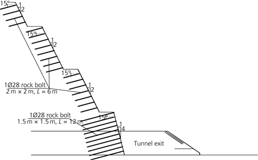
A–A section slope design of the portal
A–A section slope design of the portal
Details of support elements for slope stability
| Support element | Specification |
|---|---|
| Shotcrete | 15 cm |
| Steel mesh class | Single row Q221/221 |
| Rock bolt type | 1Ø28 |
| Steel plate | 20 mm × 200 mm × 200 mm, d = 38 mm |
| Concrete class | C30/37 |
Rock bolts are designed as L (length) = 12.00 m at a 1.50 × 1.50 m grid on all 1H/4V (horizontal/vertical) slopes and L = 6.00 m at a 2.00 × 2.00 m grid on all 1H/2V slopes. The side and front slopes in the portal are designed systematically so that the lowest slopes are 1H/4V, and the slopes to be created on these slopes are leaning as 1H/2V. Appropriate drainage measures should be taken to remove the underground and surface waters from the project area on the slopes. Therefore, drainage pipes are also designed as L = 12.00 m at a 3.00 × 3.00 m grid on all 1H/4V slopes and L = 6.00 m at a 4.00 × 4.00 m grid on all 1H/2V.
Numerical analysis
As stated by Avgerinos et al. (2017), 3D numerical modelling is an accurate and computationally efficient way to solve the tunnel–tunnel interaction problem. In addition, several researchers (Aygar and Gokceoglu, 2021c; Kasper and Meschke, 2004; Paternesi et al., 2017; Shi et al., 2016) performed 3D numerical analyses to understand the distribution of stress and deformations around tunnels. In this study, considering the highly large portal and its critical location, the analysis of the Nurdag portal with the new design of the slopes and support systems was carried out by using the Midas GTS NX 3D software, which is a finite-element analysis program. The constitutive model of Mohr–Coulomb is selected for the analysis. The Mohr–Coulomb model is generally used to model granular materials such as soil and concrete. The stress–strain relationship is considered elasto-perfectly plastic. The governing equation of this model is
where τ is the shear strength, σ is the normal stress, tan(Φ) is the slope of the failure envelope and c is the intercept of the failure envelope with the τ axis. This model involves five parameters given in Table 1 – namely, Young’s modulus (E), Poisson’s ratio (ν), cohesion (c), friction angle (Φ) and unit weight (γ). The structural elements for slope stability and TBM tunnel are also simulated in the numerical calculations; the input parameters are given in Table 3. The structural elements for slope stability and TBM tunnel are also simulated in the numerical calculations; the input parameters are given in Table 3. The soil and tunnel segment was modelled as a 3D solid element, while the TBM and grout were simulated by way of the two-dimensional (2D) plane strain element. The shotcrete implemented on the slope surface of the portal was simulated as a 2D shell element. Finally, the rock bolts that aim to provide slope stability to the surface located on the portal were modelled as a one-dimensional embedded truss element. As boundary conditions, ‘auto’ selection was used to avoid any non-logical deformations. Mesh generation was executed by using a hybrid mesh. While making the mesh, the selection of the mesh size was adjusted from small to bigger, starting from the tunnel axis to model boundaries.
Structural elements and material parameters
| Structural element | Element type | Model type | Unit weight, γ: kN/m3 | Elasticity modulus, E: kN/m2 | Poisson’s ratio, ν |
|---|---|---|---|---|---|
| Segment (35 cm) | Three-dimensional solid | Isotropic–elastic | 25.0 | 30.00 × 10⁶ | 0.15 |
| Grout (20 cm) | Two-dimensional plane strain | Isotropic–elastic | 22.5 | 10.00 × 10⁶ | 0.30 |
| TBM | Two-dimensional plane strain | Isotropic–elastic | 78.0 | 25.00 × 10⁷ | 0.20 |
| Shotcrete (15 cm) | Two-dimensional plane strain | Isotropic–elastic | 24.0 | 30.00 × 10⁶ | 0.18 |
| Rock bolt (Ø28) | One-dimensional embedded truss | Isotropic–elastic | 78.0 | 21.00 × 10⁷ | 0.15 |
The generated triple-tunnel portal model is given in Figure 12. Based on the geotechnical parameters determined for the exit portal of the Bahce–Nurdag tunnel, the displacement values expected to occur on the slopes and the effects of the tunnels on each other during the opening of the third tunnel (TBM) are presented below by using the Midas GTS NX 3D software.
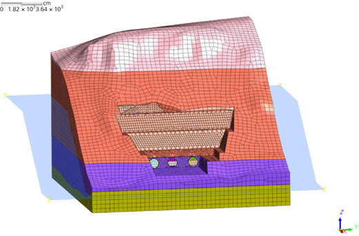
Three-dimensional Midas GTS NX model of the Nurdag exit portal
Three-dimensional Midas GTS NX model of the Nurdag exit portal
The 3D finite-element method (FEM) analysis started with the initial conditions, where the T2 tunnel has already been excavated and the slope stability at the part of the T2 tunnel has been already provided. The excavated part of the abandoned T1 tunnel has remained open. At the next step, the new slope excavation at the part of the new T1 tunnel is applied. After this stage, a support system with rock bolts and shotcrete implementation is applied to provide stability to the side and front slopes, respectively. At stage 4, the deformations are reset, and then the excavation of the T1 tunnel through the TBM with the application of the face pressure is applied. The total displacement values obtained of the triple-tunnel excavation at the face slope and at the left- and right-side slopes are 5.42, 1.43 and 3.05 cm, respectively (Figure 13). To investigate the deformations that will occur when the T1 tunnel excavation is opened in a dynamic case, the horizontal and vertical peak ground acceleration value used in the analyses is 0.25g (gravitational acceleration), according to Turkey’s Earthquake Hazard Map which is published by the Turkish Disaster and Emergency Management Authority for the tunnel site (Figure 14). The stages of FEM analysis are given in Table 4. According to the analysis, the amounts of displacement expected to occur in the exit portal face and side slopes are given in Table 5.
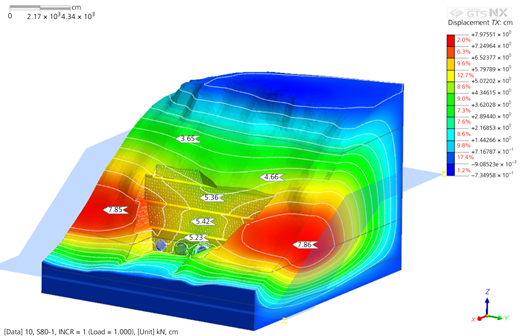
Expected displacements in the slopes of the portal (static case)
Expected displacements in the slopes of the portal (static case)
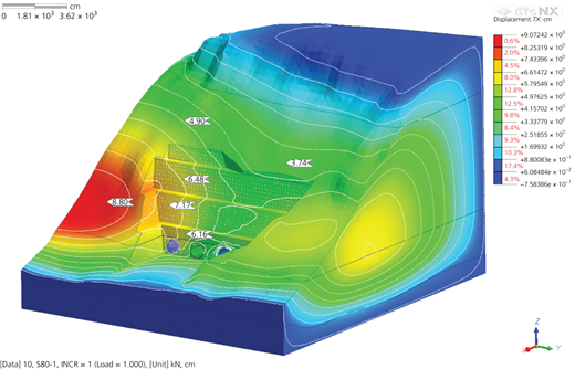
Expected displacements on the slopes of the portal (dynamic case)
Expected displacements on the slopes of the portal (dynamic case)
Modelling and analysis stages of the portal in the Midas GTS NX 3D software
| Stage | Description |
|---|---|
| Initial phase | The T2 tunnel has already been excavated, and slope stability at the part of the T2 tunnel has already been provided. The excavated part of the abandoned T1 tunnel has remained open. |
| 1 | Excavation of the new slopes at the part of the new T1 tunnel |
| 2 | Application of rock bolts to provide stability of the side and front slopes |
| 3 | Shotcrete implementation to the slope |
| 4 | Resetting to the displacements |
| 5 | Excavation of the T1 tunnel through the TBM with the application of the face pressure |
| 6 | Application of the segments of the TBM |
| 7 | Safety calculation of the system for the static case |
| 8 | Application of the horizontal seismic load to the model |
| 9 | Calculation of the factor of safety of the system for the dynamic case |
Maximum displacements obtained from the analyses
| Maximum displacement: cm | |||
|---|---|---|---|
| Face slope | Left-side slope | Right-side slope | |
| Static case | 5.42 | 1.48 | 3.05 |
| Dynamic case | 7.17 | 2.73 | 5.02 |
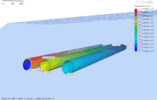
The horizontal and vertical displacements obtained from the numerical analyses of the slopes remained within safe limits. This shows that the designed support system has successfully fulfilled its task. Besides, it has been observed that the third tunnel construction has no effect on the existing tunnels. Figure 15 shows the total displacements expected to occur after the new tube is excavated.
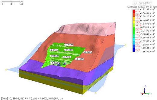
In Figures 16 and 17, the moment and the axial force on the shotcrete that are obtained to verify the support elements design are given, respectively. The axial force and moment on the shotcrete obtained for the static and dynamic cases are given in Tables 6 and 7, respectively. For the static case, these values are multiplied by a safety factor of 1.6. Figure 18 shows that the design values remain within acceptable limits in the N–M (axial force–moment) interaction curve. This curve is a strength envelope, and this means it can safely carry extra loads. Consequently, it is seen that selected support elements are adequate. In the cross-sectional verification, the single-row Q221/221-type reinforcement mesh is selected. In the verification analysis, the thickness of the shotcrete was taken as 15 cm; the rock bolt type is selected as 1Ø28.
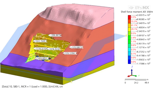
Axial force values on the shotcrete
Axial force values on the shotcrete
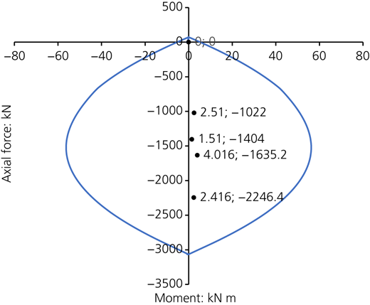
N–M interaction diagram on the shotcrete
N–M interaction diagram on the shotcrete
N–M interaction on the shotcrete (static case)
| Values obtained from the FEM analysis | Values multiplied by safety factor of 1.6 | |||
|---|---|---|---|---|
| Moment: kN m | Axial force: kN | Moment: kN m | Axial force: kN | |
| Force Couples-1 | 2.51 | 1022 | 4.016 | 1635.2 |
| Force Couples-2 | 1.51 | 1404 | 2.416 | 2246.4 |
N–M interaction on the shotcrete (dynamic case)
| Values obtained from the FEM analysis | ||
|---|---|---|
| Moment: kN m | Axial force: kN | |
| Force Couples-1 | 3.69 | 992 |
| Force Couples-2 | 3.56 | 1545 |
The stability analyses in both the static and dynamic cases of the portal face and the side slopes were performed using the general limit equilibrium/Morgenstern–Price method, which gives critical results, because of considerations of the forces in the calculation of equilibrium conditions. In the Morgenstern–Price method, the interslice shear force is related to the interslice normal force by
where X is the interslice shear force, En is the interslice normal force, λ is a constant scale factor and f(x) is a prescribed function that dictates the variation of the X/En ratio along the slip surface (Morgenstern and Price, 1965).
According to the analysis results, the safety factor of the face slope was calculated as 1.72 and 1.11 (Figures 19(a) and 19(b)), and the side slopes were calculated as 1.91 and 1.45 (Figures 20(a) and 20(b)), under static and dynamic conditions respectively. In the relevant regulations (Ground Anchors and Anchorage Systems (FHWA-IF-99-015) (Sabatini et al., 1999: pp. 96–118)), it is stated that the minimum safety factor should be 1.5 under static conditions and 1.1 under dynamic conditions. Considering this requirement, it is seen that the values obtained as a result of the analysis are above the minimum requirements. This shows that the designed support system has successfully fulfilled its task.
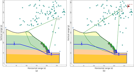
Stability analysis of the portal face slope: (a) static case; (b) dynamic case. W, water table
Stability analysis of the portal face slope: (a) static case; (b) dynamic case. W, water table
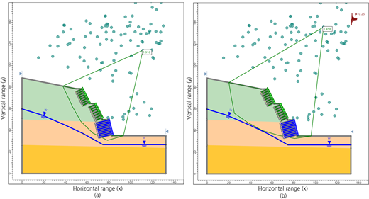
Stability analysis of the side slopes: (a) static case; (b) dynamic case. W, water table
Stability analysis of the side slopes: (a) static case; (b) dynamic case. W, water table
Conclusion
In the study presented, possible recovery alternatives for the T1 tunnel of the Bahce–Nurdag tunnels that had a TBM jamming problem have been evaluated. As a result of all the evaluations and analyses, it was understood that the recovery of the abandoned T1 tunnel was theoretically possible, but from a safety and economic point of view, it was not the right choice. For this reason, it was clear that leaving the existing T1 tunnel and constructing a new tunnel is the most appropriate option. According to the site investigations and observations, the conditions of the portal area allow the opening of a third tunnel. However, considering the project and the project area, three tube tunnels, a large portal, a highly seismic region and very steep topography are the critical elements of the study. The combination of these critical elements makes the project extremely difficult, and there are important interactions of these elements. Consequently, obtaining the deformations caused by the interaction of these critical elements with each other is possible with 3D modelling in a plausible and reasonable way. The stability of the portal slopes and the 3D numerical analysis of the tunnel entrance section were carried out by using the Midas GTS NX 3D software program. The geological–geotechnical sections and parameters used in this analysis are concluded to be suitable. Furthermore, it has been understood in the analysis that the safety level has been reached for both static and dynamic conditions in the slopes. An 8 m heel between the existing T1 tunnel and the new tunnel is sufficient according to the 3D model of the portal.
The analysis results showed that the safety factors remained above the minimum required value in both static and dynamic cases. In the displacements examined with the Midas GTS NX 3D software program, the maximum displacement was observed as 5.42 cm in the face slope in the static case and 7.17 cm in the face slope in the dynamic case. Although the observed maximum displacement values remain within the limit values, it was observed that the most critical region in the tunnel portal is the face slope.
In line with the results obtained, it has been observed that the revised support system has successfully constructed and fulfilled its task. It is concluded that the suggested improvement methodology and the support systems are satisfactory. This study was able to conclude that 3D FEM is a useful tool for simulating the mechanism of tunnel excavations and large portal design in highly seismically active regions.

