Grey cast iron water pipe networks have been installed around the world, often 100–180 years ago. Cohorts (which can be defined by age, size, casting technology and geographical location, to specify but a few groups) degrade at different rates due to environmental and in-service issues, which can lead to a significant loss in mechanical performance. Hence, the management of these assets can be extremely problematic in terms of identifying priorities. The current paper considers the causes of such degradation, the consequences for defining accurate and up-to-date condition assessment protocols and hence the type and urgency of rehabilitation strategies. It follows that understanding the integrity/life expectancy of water networks requires non-destructive evaluation (NDE) of large-diameter cast iron trunk mains, with particular reference to the kinds of defects that are likely to be present and the issues that make assessment difficult. From this, recommendations are outlined for asset managers required to specify NDE protocols, based on an understanding of the nature of the material and conditions in the field.
Notation
Introduction
Large-diameter trunk mains, with diameters of the order of 12–60 in. (300–1500 mm), are vital components of water networks around the world, conveying large volumes of water over long distances. Cast iron was considered to be the wonder material of the Victorian era (Gagg and Lewis, 2011). Stilgoe considered this still to be the case in the early part of the twentieth century: ‘I can always say of the Cast-iron Water Main that it is a well-tried, faithful, and honest servant of the Water Engineer’ (Stanton Iron Works Company, 1936: p. xiv). Hence, many trunk main made of grey cast iron and installed 100–180 years ago are still in service today.
This ageing cast iron infrastructure is deteriorating at different rates (Atkinson et al., 2002; Rajani and Makar, 2000): when sufficiently degraded, it can burst, leading to flooding, property damage and disruption of supply and local transport. Such issues have multiple impacts, raise concerns over public safety and lead to customer dissatisfaction. The risk of a burst can be reduced by replacement programmes, but rehabilitation or renewal can cost millions of pounds per kilometre. Therefore, asset managers need models, fed with accurate data from the field, to target replacements strategically.
Non-destructive evaluation (NDE) has been routinely carried out on ferrous oil and gas pipelines for many years (Roberge, 2007), and it is perhaps not surprising that discussion of the NDE of water networks either begins with, or rapidly turns to, methods deployed in the oil and gas industry. However, what is often overlooked is that many of the challenges facing water networks have not been present in the oil and gas industry or are more easily overcome. Compared with cast iron water trunk mains, these pipelines are straight, well protected against corrosion and constructed from thinner steel (of a consistent microstructure), with facilities for their future inspection. In contrast, water pipes were constructed from thicker sections of cast iron (of heterogeneous microstructure and varying quality), with little protection against corrosion, buried without thought for their future inspection and in the urban context are connected to many smaller pipe networks which directly supply customers.
Water quality is a significant, and legislative, issue placing further constraints on the application of NDE techniques: the taste and odour, not to mention the potability (in terms of acceptable bacterial, particulate and chemical concentrations), must not be compromised by internal or external assessment. With regard to internal assessment, discolouration is also a risk that must be mitigated (HMG, 2000). Further, any NDE used must not damage the pipe such that its remaining life is shortened. Consequently, conducting NDE is significantly more challenging than just finding cracks and other defects.
Starting with a detailed review of the nature of defects and their effect on the strength of pipes, this paper provides context for the various defects that require characterisation in order for asset management models to be informed suitably. The difficulties in collecting such data in the field are also considered and the requirements for data collection by NDE in ‘real-world’ situations determined.
The nature of defects and their effect on the strength of pipes
What is a defect?
A trunk main can be idealised as a cylinder of consistent diameter, uniform thickness and homogeneous microstructure in which failure occurs when the stresses in the main exceed the strength of the material. However, old cast iron trunk mains contain myriad defects, which may act as stress concentrators, reducing the loads that the main can withstand. These defects can be split into three categories: defects produced during manufacture, defects induced during installation and defects arising throughout service.
Manufacturing defects
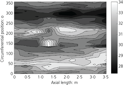
The properties of cast iron are controlled by the graphite flake structure (Angus, 1976). The use of this material spans several technological advances; hence, cohorts of pipes have been manufactured using successively improved processes, leading to products of greater reliability. Initial production used horizontal pit casting and then moved to vertical pit casting before arriving at spin (or centrifugal) casting. These developments led to a greater uniformity of wall thickness and a more refined microstructure with smaller graphite flakes and improved mechanical properties (Stanton Iron Works Company, 1936). A significant problem with characterising any network that has developed over a significant period is that the stock is extremely variable in terms of manufacturing technique and quality. Variation in wall thickness was reduced, and defects arising from misalignment of internal and external moulds were reduced by the move from one technology to another and indeed by improvements in each technique, where adopted by reputable manufacturers. However, it is not unusual to see variations in the wall thickness of pipes. Figure 1 presents a contour map based on physical measurement of a vertically pit-cast pipe dating from the 1920s and produced by the renowned Stanton Iron Works Company. The pipe, which can be considered to be of the highest quality available at the time, still shows some ±10% variation around a nominal average thickness.
Other possible casting defects, which also diminished because of advances in manufacturing techniques, include porosity, slag inclusions and so-called cold shuts, where two fronts of molten iron fail to fuse properly due to premature cooling.
Installation defects
Following manufacture, the cast iron pipes were transported to site for installation on trucks and trailers and would either be rolled down planks of wood from the edge of the truck or be lifted with a crane. It has been suggested that pipes handled this way were susceptible to damage from collisions between the pipes and other external bodies. Not all impacts would produce a visible crack: an internal crack in the bell or spigot (Rajani and Kleiner, 2010) would not necessarily be detected by on-site hammer testing typical of the time. Additionally, the use of chains for pipe handling rather than canvas slings is known to have damaged the protective outer coal tar or bitumen coating, leaving areas of bare metal.
Once the pipes were in situ, the joint would be packed with hemp to form a seal, filled with molten lead and finally caulked by hammering the solidified lead into the joint (Rajani and Abdel-Akher, 2013; Stanton Iron Works Company, 1936). If the caulking was carried out incorrectly, the lead would be hammered too far into the joint, leading to an increase in stress around the joint, potentially causing a crack to initiate. A worst-case scenario would see poor caulking practice expand a crack created during the siting of the pipe. This could result in a structurally flawed pipe with a reduced service life.
Service-induced defects
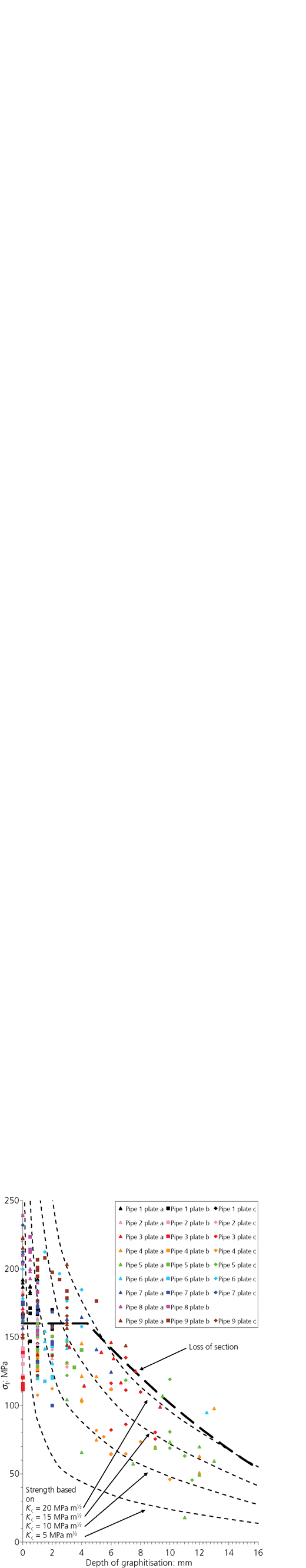
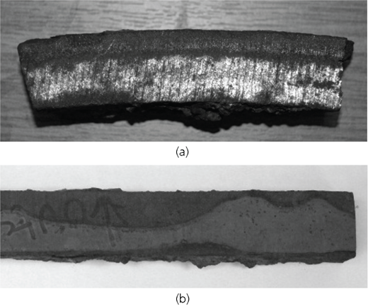
Once in service, mains are subject to further mechanisms that can cause defects to form and grow until the defects are too large for the pipe to sustain. In places where the bitumen or tar coating is compromised (often as a result of the installation process as mentioned earlier), corrosion processes are initiated which can further undercut the coating, causing it to spall, expose bare metal and continue to corrode. Of particular concern is ‘graphitisation’, which should properly be termed ‘graphitic corrosion’ (Logan et al., 2014a, 2014b). Despite anecdotal assertion, it is generally not possible to identify graphitic corrosion by visual inspection in exposed pipes since the corroded region does not change in volume (although the density decreases) and the pipe appears unaffected to the naked eye. This may reduce the residual strength capacity of the pipe (Figure 2).
Graphitic corrosion is identified by two distinct areas: a passive, grey, brittle, corrosion product and an active transition zone, typically 1–2 mm deep, bounded by the corrosion product on one side and the virgin iron on the other, where the corrosion process occurs (Logan et al., 2014a, 2014b). The corrosion product has been seen to occur in two broadly defined topologies (Figure 3): a uniform thickness over large areas or more localised pits with both diameter and depth of the order of 10 mm. It is the more localised corrosion that is potentially more damaging as it provides a stress concentration at its root, which in the worst case can be thought of as a crack.
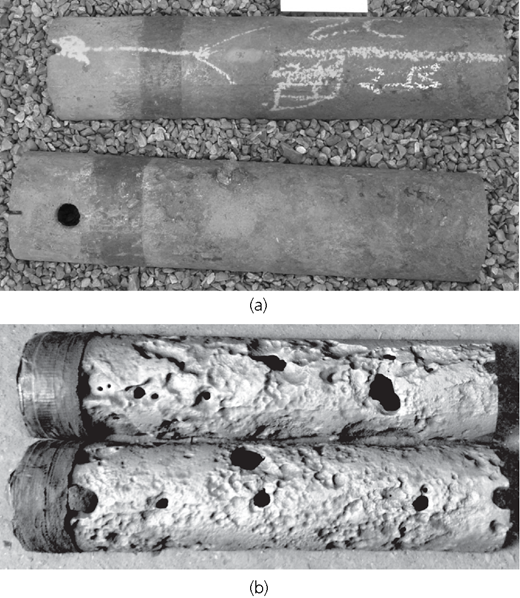
In smaller-diameter distribution mains, graphitic corrosion has been shown to have a significant impact on the strength of the pipe and to be in competition with defects that have originated during manufacture and installation. Further, because of the combination of the size of the pipe and its interaction with the local environment, it is possible to comment on the behaviour of the main a significant distance (multiple casting lengths or ‘sticks’ of pipe, typically 3–5 m long) either side of a sampling point (Belmonte et al., 2007, 2008, 2009). The size and spread of graphitic corrosion in distribution mains can be seen in Figure 4.
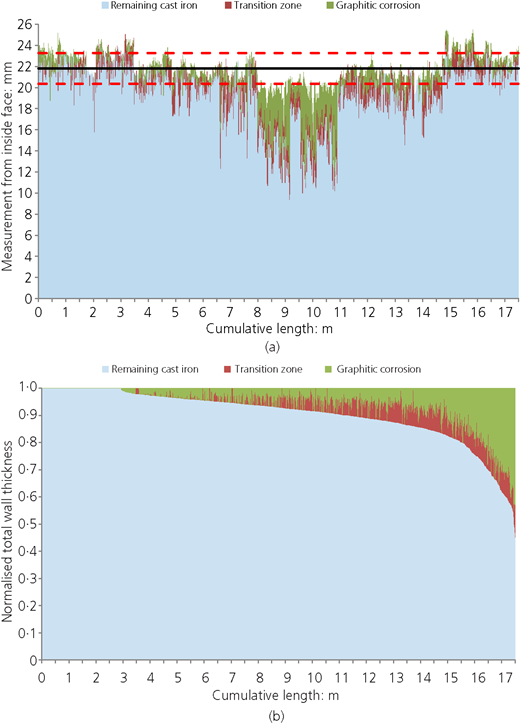
In larger-diameter trunk mains, however, the size of the pipe and hence the volume of ground that it interacts with mean that similarly sized samples taken from different parts of the same stick can give very different results (Jesson et al., 2013). As part of the present work, the distribution of the depth of graphitic corrosion over single sticks, from each of the mains for which strength data are shown in Figure 2, was assessed and observed to vary greatly across the stick. Figure 5 shows an example of the data observed for one stick. The variability means that any evaluation technique must consider the whole surface of the pipe (albeit ignoring the difficult geometry of the bell and spigot) in order to provide a meaningful assessment of a pipe. In conjunction with the variation in the depth of graphitisation from point to point within the trunk main pipe, it should be noted that the stress, arising from a combination of vertical load (due for instance to soil and traffic) and water pressure, will vary with position around the pipe. These effects were considered in a recent paper by Fahimi et al. (2016).
Finally, in terms of service-induced defects, it is worth noting that fatigue, potentially induced by operational pressure variations and traffic loading, has been cited as a problem, particularly in connection with the growth of installation defects (Rajani and Kleiner, 2010). This assertion is predicated on the presence of a substantial initial crack (of the order of 20 mm) which needs to grow by only a small amount (1–2 mm) to cause catastrophic failure. Experimental work on the fatigue properties of cast iron presents a somewhat mixed view. It perhaps seems more likely that fatigue may be a contributory factor when taken in conjunction with corrosion: these two may combine to cause premature failure (Belmonte et al., 2009). Cast iron is known to undergo mechanical fatigue (Angus, 1976; Belmonte et al., 2009; Mohebbi et al., 2010), although it should be noted that a specific mechanism which combines both fatigue and corrosion has not been established.
Assessing condition in the field
Overview of NDE techniques
Every NDE technique has strengths and weaknesses: there are several excellent reviews on such techniques and their specific capabilities (Costello et al., 2007; Dingus et al., 2002; Dorn et al., 1996; Hao et al., 2012; Jackson et al., 1992; Liu and Kleiner, 2013; Prinsloo et al., 2011; Thomson et al., 2009); key features of these reviews are summarised in Table 1. All of these papers review the literature regarding NDE and explain the operation of each technique. In some cases, the results of field tests that evaluate each NDE technique’s efficacy on cast iron main are given. However, such reviews, while providing an insight into potential NDE techniques that may be applicable to cast iron, rarely consider the different types of defect and the challenges in finding such defects in a buried pipe in service (‘live’) in the field. Where field results have been obtained, the results consider only inspection carried out internally on small-diameter pipes. Little consideration has been shown for techniques that can be applied to the outside of the pipe, nor on the techniques that could be used to inspect much larger trunk main. Ultimately, many of the reviews identify very similar tools for potential use on cast iron pipes, rather than describing how their methodology may be applied to the pipe or locating specific defects.
What does NDE need to do?
The risk of a trunk main burst and the need for proactive NDE to inform targeted rehabilitation and replacement to avoid these bursts are clear. The suitability of a technique for this application must be determined, particularly when it is borne in mind that corrosion processes may occur at both external and internal surfaces and that other defects (such as cracks, voids, cold shuts and inclusions) may exist throughout the section. The application of NDE to a cast iron trunk main is further complicated by the challenging environment in which inspection must be carried out.
In this section, the type and size of defects which must be sought to prevent failure in a worst-case scenario are considered further and an order of priority advised. This is important as certain defects may be more detrimental than others to the remaining service life of the main since they can continue to grow until failure ensues. Finally, the logistics of conducting an inspection on a trunk main and other issues for NDE of a cast iron trunk main are also described.
Which type of defect is the most important to locate?
Determining what the NDE is trying to find requires a good understanding of what indicates a poor condition. While the defects mentioned previously could all contribute to failure, some are more likely to cause failure than others. Corrosion has been shown to severely reduce the structural performance of cast iron (Jesson et al., 2013; Yamamoto et al., 1983) and must be a priority for inspection. It is also important to establish the level of sound metal remaining in the pipe, particularly as geometric disparities such as wall thickness variations, not necessarily known about beforehand, can further concentrate the stress around the corrosion and further weaken the pipe.
Following on from corrosion, cracks also present a significant risk to the structural performance of the pipe as they have the potential to grow until failure. It would be beneficial to be able to identify the location and dimensions of any cracks, particularly if there is a potential for them to intensify further the stress due to an interaction with another defect present. However, finding small cracks is likely to be the most demanding requirement to meet: it must be remembered that it is more important to find a subcritical crack with the potential to grow than it is to find a critical crack. (This is discussed further in the section headed ‘What is the required resolution of the NDE technique(s)?’) In addition, such defects may be hidden under corrosion and/or accretions of location material, further obfuscating NDE assessments of cracking.
Finally, it would also be beneficial for asset management if the presence and location of porosity, inclusions, cold shuts and other such defects could be determined, to characterise the condition of a pipe fully. However, if the defect populations introduced at manufacture have not led to early failure, they are likely to be in a stable state and may not lead to failure in the near future, unless combined with newer defects. Hence, the detection of cracks and corrosion, both of which tend to worsen over time, is of much greater importance.
What is the required resolution of the NDE technique(s)?
Treating, for the moment, all defects in the same manner – that is, as cracks – their size informs the resolution and accuracy required of the NDE methods. Conlin and Baker (1991) demonstrated the use of fracture mechanics on cast iron to determine the size of the critical defects that would cause catastrophic failure. Fracture mechanics gives a relationship between the applied stress σ; the crack ‘length’ a (in this case the depth of penetration into the wall) and the resulting intensified stress at the crack root, termed the ‘stress intensity factor’, K (where Y is a crack geometry-dependent, dimensionless constant)
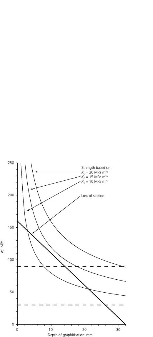
The critical stress intensity factor K c, which may also be referred to as fracture toughness, is a material property. As noted in Figure 2, two cases can be considered – that is, loss of section and fracture mechanics – with these two models providing an envelope capturing the majority of failures. For illustrative purposes, a thumbnail crack geometry is assumed (for which K = 1·26σa 1/2); the relationship between tensile strength for catastrophic failure and crack size is shown graphically in Figure 6 for a range of fracture toughness values for cast iron taken from the literature (Ashby and Jones, 2005). A value of 90 MPa was suggested by Marshall (2001) as the maximum value of stress that a pipe would experience in service. This stress would mean that crack lengths greater than 8 mm in a material with a fracture toughness K c of 10 MPa m1/2 would cause fast fracture. Conversely, for cast irons with K c greater than or equal to 14 MPa m1/2, failure would occur by loss of section when the crack becomes 14 mm long, if the original wall thickness is 32 mm. More recent work by Rajani and Abdel-Akher (2013) suggests that this value of operating stress is higher than what is routinely seen in practice; based on this, a value of 30 MPa is used as a more ‘realistic’ estimate. In this situation, longer defects could be tolerated before catastrophic fracture.
The fracture mechanics predictions allow some tentative observations to be made on the possibility of a leak-before-break in cast iron water mains. In simple terms, the leak-before-break condition requires the critical crack length at the operating stress to exceed the pipe wall thickness. Based on the analysis used to make the fracture mechanics predictions in Figure 6, this condition is met; hence, a leak-before-break may occur in this example. This requires additional investigation because of the uncertainties regarding the level of working stress and details of possible defect shape, which would modify the stress intensity factor. Further, for a given working stress, a leak-before-break becomes more likely in pipes with a smaller wall thickness. Leakage from permeable through-wall graphitic corrosion has been observed previously in distribution mains (Jesson et al., 2010). Anecdotally this phenomenon has also been observed in trunk mains.
The implication of the data presented in Figure 2 and the analysis in this section is that in order to be truly useful, an NDE technique must be able to detect reliably graphitic corrosion depths of the order of 4 mm and greater, to a resolution of ±1 mm. The surface resolution would ideally be comparable to this, but in practice may be constrained by the physics of the NDE technique itself, by practicalities associated with data storage or by the time needed for scanning.
What are the challenges posed by the field environment?
It is an aspiration that the condition of a buried asset could be assessed from above ground without the need to excavate the pipe, thus saving time and expense. The Engineering and Physical Sciences Research Council (EPSRC)-funded UK research programmes Mapping the Underworld and, more recently, Assessing the Underworld, have been working to determine what underground assets can be successfully inspected without being exposed. While progress on identifying the location of a buried asset has been made, no methods of NDE have shown the ability to detect the defects discussed here either above ground or by using point assets, such as valves or hydrants, as access points (Hao et al., 2012).
Consequently, whatever the optimum NDE technique is found to be for the collection of condition data, the ideal deployment would be through an inspection system which can pass along the inside of an in-service main. The device could have an umbilical cord or a winch cable, but to enable greater survey lengths, it would ideally be propelled by the flow of water (such a tool often being referred to as an intelligent pig, a smart pig or an inspection pig). In principle, this would allow large portions of the network to be inspected without disruption to supply. However, in practice, this is problematic as the implications for water quality cannot be ignored and must be considered in the ultimate deployment methodology of the NDE sensor/instrumentation package. Here the physical contact of the sensor and/or the carrier with the pipe wall is likely to cause surface deposits to be dislodged or, in a worse case, may damage corrosion prevention measures (e.g. bitumastic coatings). In a worst-case scenario, protruding corrosion features (known as tubercles) can be damaged by internal NDE, leading to chronic water quality issues and accelerated internal corrosion due to the removal of the passivated layer. Lining a main can reduce problems with water quality during internal NDE, but this is costly and further impedes NDE. Hence, the use of an inspection pig is likely to require the main to be taken out of service during inspection and subsequently flushed. The use of this technology would also require a significant amount of network modification to enable a pig to be inserted and retrieved from the network, and a device or a collection of devices that could cope with the range of mains diameters in use (12–60 in or ~0·305–1·52 m). It must be capable of both recording its own position and being located from the surface. Lastly, the pig must be capable of traversing a trunk main which may change direction or depth along its length and could have offtakes: some pipes are not always easily accessible if the device should become stuck (Dingus et al., 2002; Vickridge and Lau, 2000). Further, if ‘pigging’ is to become an industry standard, it must be capable of assessing corrosion (and ideally the other defects discussed in this paper) reliably, through the full wall section.
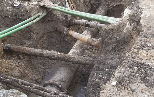
Hence, conducting NDE from the outer surface of the pipe is currently preferable, even if it means that the pipe must be excavated for NDE to be conducted. Very often mains are exposed for routine work, which may present sufficient opportunity to assess the mains condition while the excavation is still open. However, this is still not without challenge. An excavation creates a muddy trench and may expose only a small section of main (approximately 1 m long), which is not significantly longer than the pipe’s diameter. This can leave limited access to the surface of the pipe, particularly underneath the pipe (Figure 7). Any NDE method will need to be capable of operating within the clearance around the pipe afforded by the excavation and the neighbouring utilities.
Following on, the NDE method must be capable of dealing with an outer surface which is often hidden by a well-adhered layer of surface encrustation which is formed from the soil and aggregates around the pipe, and in some circumstances, iron leached from the pipe may react with the soil and the aggregates to form a binder, increasing the tenacity of the encrustation to cling to the surface. This can be removed but it must be done carefully so that the pipe is not compromised or the degradation accelerated. Even once removed, the surface can be seen to be heavily pitted. This is a long way from the smooth surfaces seen in the aerospace industry, where NDE techniques are routinely used. Finally, NDE must be capable of penetrating thick sections of cast iron, of the order of 35 mm.
Specifying NDE protocols in support of asset management
Fundamentally, then, what does NDE need to achieve for cast iron infrastructure? It needs to (a) collect meaningful data about the condition of specific assets and (b) provide these data in a form that can be used by asset managers to improve their decision-making processes. In the context of the present paper on pipes, the condition data collected should be able to accurately locate a number of key features
section thickness
manufacturing defects, such as porosity (where possible)
the extent of internal and external corrosion
the presence of internal and external cracks.
Of course, this list can be applied generically and forms a useful starting point for dealing with any cast iron asset. Further, it must be recalled that the collection of these data must take place in difficult circumstances. This places an onus on asset managers in that they must be careful to specify the data to be collected, the form that it is to be collected in and any preliminary steps that must (or must not) be taken. However, there is also an onus on contractors to specify the necessary conditions required for successful collection of NDE data. On this basis then, the key steps in an NDE process are
preparing the surface with minimal destruction to the pipe (or other assets)
conducting NDE in an agreed space around the pipe, which is likely to be limited
reporting the data in the format defined by the network operator.
Some form of validation testing, that is to say a piece of cast iron which is assessed through NDE and then dissected to match observed defects, is a useful step in assessing any given NDE technique offered for use on cast iron infrastructure.
In the Appendix, a number of techniques are considered for application. These are taken from the review papers discussed earlier and then reviewed in the light of a potential field test, or with respect to other issues such as legislation or risk to the public perception of a network operator. From this it can be seen that while a plethora of NDE tools exist, and could potentially be applied, there remain difficulties in actually using the majority of these options. A very few NDE techniques can be applied to cast iron, but the resolution of defects remains poor and requires much calibration and development if they are to be viewed positively by asset managers.
Concluding remarks
Networks of ageing cast iron mains supply drinking water to millions of consumers around the world, and any interruption in supply associated with pipe failure, catastrophic or otherwise, is both undesirable and problematic. As a consequence, network operators seek to reduce the occurrence of failure by proactively targeting and replacing high-risk mains. The failure of cast iron mains has been linked to a range of defects present in the pipes, including those present at manufacture and those created during installation or induced through degradation during extended periods in service. This last group of defects is primarily associated with graphitic corrosion, which is known to contribute, both directly or indirectly, to a significant proportion of cast iron water main failures. Graphitic corrosion has significant implications for the remaining load capacity of a pipe. Hence, the extent of corrosion, its conformation and the remaining wall thickness must be assessed and quantified in order to predict reliably the remaining life in service.
The methods used to perform NDE on materials and engineered systems are diverse, and various physical properties are used to assess the ‘health’ of cast iron infrastructure. These include methods based on the magnetic and electrical properties of the cast iron, as well as the speed of elastic waves – for example, ultrasound – through the material, or the absorption of X-rays. Such methods rely on the detection of some level of change in the properties associated with the presence of an unexpected secondary phase, the degradation due to the presence of corrosion or cracking. Other methods for checking pipe integrity include those that ‘listen’ for leaks or the use of a solution that bubbles when it comes into contact with, usually, leaking air. Many of these techniques are routinely deployed in a number of industries, and their effectiveness is well documented and standardised. With respect to the use of NDE in the water industry, there have been a number of detailed reviews that consider NDE as a whole, specific branches of NDE or NDE in a particular context. However, they focused less on applying the filters of the field environment and the working practices of the industry. A number of well-established techniques are limited to the laboratory, as they are unlikely to be practical in the field, are regulated against or do not take into account the inherent variation in microstructure (and properties) of cast iron. For example, while ultrasonic inspection is routine in the aerospace sector, a few millimetres of aluminium is a very different prospect from tens of millimetres of cast iron, particularly when the cast iron is corroded. The graphite flake structure of the metal acts to dissipate the ultrasonic signal, and the transition zone of active corrosion is strongly attenuative rather than giving rise to a clean reflection.
A significant problem for any NDE technique is accessing the structure to be assessed: with buried assets, inspection must rely on either exhumation or, if possible, an internal assessment. Both scenarios present significant issues, particularly in the context of a water main. Further, in either case, once access has been achieved, surface preparation is often required to ensure adequate measurement quality, and that process can lead to the asset being damaged. Such damage may or may not be immediately apparent, but will reduce the residual life of the asset being assessed.
These comments notwithstanding, ultrasonic inspection, although facing the hurdle of poor surface condition, would appear to have the best opportunity of finding all of the defects discussed in this paper, but significant work is required to overcome the issues that the presence of graphitic corrosion presents to meaningful data collection and interpretation. It may be best to pair ultrasonic inspection with another technique (such as eddy current testing, or magnetic flux leakage, MFL) to provide complementary results that can be combined together to give a complete, composite picture.
Given the potential length of water networks and the range of soil environments in which they are situated, external NDE conducted in small excavations can only give a snapshot of the local pipe condition. Statistical analysis can allow these data to predict the condition of nearby pipes and asset managers can use further analysis to consider cohorts of similar pipes by using data from across the network to make a decision about a specific pipe. However, greater (contiguous) lengths of the network must be inspected to understand its condition more fully. At present, a device capable of characterising the range of defects typically present in cast iron main at the physical resolution suggested does not exist. Further developments in this area must be made if any certainty on the condition of the trunk main networks is to be obtained.
Acknowledgements
The authors gratefully acknowledge the funding provided for this research by the EPSRC (grant EP/G037388/1, through the Micro- and Nanomaterials and Technologies Centre for Doctoral Training, University of Surrey) and by Thames Water Utilities Limited. The authors would particularly like to thank Dr S. A. Adegbite, formerly of the University of Surrey, for useful suggestions to this paper and for his contribution to the larger project of which this paper is a part.
The opinions expressed in this paper are those of the authors and not necessarily endorsed by the University of Surrey or Thames Water Utilities Limited.
Appendix Application of NDE techniques
Introduction
A plethora of NDE techniques are available to determine the condition of large structures. While the spectrum of techniques is broad and difficult to compare, the principle of NDE may be summarised as the exploitation of a physical material property in order to assess condition against some empirical or notional base line. For the fundamentals of a specific technique, the reader is referred to the reviews mentioned earlier in this paper, or to a suitable textbook such as that by Halmshaw (1991) or Cartz (1995). It is not the purpose of this paper to critique the operation of one technique compared with another: rather, it is to identify the physical practicalities which affect a technique’s ability to be applied to cast iron trunk main. In particular, the ability of the techniques to identify each category of defect outlined earlier from the outer surface of the pipe is discussed. Other considerations such as the safety implications, space requirements and practicalities are also considered and used to eliminate techniques which are unlikely to be feasible for inspection of a live main.
A reasonably comprehensive list of NDE techniques might be expected to include ultrasonic, MFL, eddy current, acoustic, radiographic, dye penetration, visual and pit depth measurements. However, in practice many of these techniques are unsuitable.
Unsuitable methods
Constrained by safety
Dye penetration testing requires the use of a fluid dye which must not enter the water supply but could be drawn in through a through-wall crack.
Radiographic inspection with gamma rays or X-rays carries immediate health risks and would require an extremely powerful source and lengthy exposure time to penetrate the thick cast iron. Given the small exposure area, this process would need to be repeated several times to build up a complete image of the pipe successively. Furthermore, the inspection would have access only to the outer surface of the pipe, which would mean that the radiation source and detector would be sited either side of the pipe, effectively doubling the material that the rays would need to penetrate. Hence more powerful X-rays with longer exposure times would be needed, increasing the health and safety risks. Finally, there is a public perception issue regarding the deployment of radiographic equipment and associated shielding, barriers and signage in urban areas.
Constrained by working space
Remote field eddy current techniques have been shown to assess the level of corrosion on a main well, but it would be impeded by the available space in the excavation (Dingus et al., 2002). Hence, the technique is suited to an inspection pig application since it requires a substantial separation, on the order of two pipe diameters (Hao et al., 2012), between the exciter and the detector. This is unlikely to be possible in an excavation where space may be limited.
Constrained by damage to the asset
It is feasible to gather visual condition data on the level of external corrosion by mechanically removing corrosion products and measuring with more or less accuracy the pits which are revealed. However, this is a partially destructive method which, while providing a useful measure of corrosion, could lead to problematic situations for an in-service main. If through-wall corrosion is present, disturbing it may lead to a leak or, worse, failure of the pipe.
Constrained for other reasons
Passive acoustics are used in water mains to detect leaks but can also be employed to listen for mechanical deterioration in a structure, such as the wires breaking inside a prestressed concrete pipe (Travers, 1997). This method can be applied only to situations requiring continual monitoring and not inspection as it can only measure the deterioration since it was installed rather than providing a complete instantaneous picture of condition (Makar and Chagnon, 1999). It is questionable whether such an approach is relevant in the context of the subcritical growth of a crack. Presupposing that such a crack has been identified and a sensor placed at an appropriate location to monitor ongoing crack growth, such a detector would need to be capable of detecting the energies associated with crack growth at a scale of the order of 1 μm per cycle (Mohebbi et al., 2010) while also being subjected to a range of other events found in live mains, in particular those under busy roads.
Active acoustic methods such as modal analysis, where the frequencies at which an object resonates are monitored and compared to a known reference, as in the traditional tapping test of a train wheel for identifying a flaw, have also been suggested. For a buried water pipe, the different volumes and types of earth which surround it, and the large volumes of water within it, can affect greatly the resonances of the pipe wall (Leinov et al., 2015). Such environmental variations may be very difficult to factor in to the reference; hence, the results obtained may be negated. At higher acoustic frequencies, shorter-range guided waves might be used to inspect trunk mains. This technique is often used to inspect long lengths of welded pipes where the waves can progress between lengths of pipes. However, the bell and spigot joint between sticks on trunk mains would limit the wave progression between sticks.
Non-contact strain measurements which use interference optical methods such as holography and shearography may be challenged by the environment in which to perform measurements on a large pipe. Preparing the surface sufficiently well to use precision optical equipment in such a context would be very demanding, and it is doubtful that an excavation on trunk main could provide a suitable environment for such optically based NDE methods to function.
Visual inspection may not be sufficient on its own but would be a precursor to any other technique, allowing information, such as casting marks, the environment in which the pipe sits and the presence of other utilities or traffic loadings, to be assessed. All this information can contribute to a ‘health check’ of a pipe. If the pipe is badly deteriorated to the naked eye, then this may negate the need to proceed with further inspection.
Potentially suitable techniques
MFL shows some potential for the inspection of cast iron and is already commercially available as an inspection technique (Liu et al., 2012). However, there are some questions over the efficacy of the method in characterising defects in the pipe wall. In particular, the often poor surface condition present on an exhumed trunk main can make it challenging to ensure that the tool is in full contact with the pipe wall. Failure to maintain full wall contact does not ensure that the magnetic field generated by the magnets is coupled to the pipe wall consistently and can lead to difficulties with accurately determining the size and shape of the defect as the tool’s capacity to capture the flux leakage around a defect is linked to the spacing between the tool and the pipe wall. Further, the sensitivity of the tool is reduced for greater wall thicknesses as it becomes progressively harder to detect magnetic flux leaking from the distant wall with a system stationed at the proximate wall (De Silva et al., 2002). Given the operating principles of MFL, it seems very unlikely that narrow cracks will be detected because it is debateable whether the crack will provide a sufficient discontinuity for the flux to leak out of the pipe.
Eddy current technology, using low-frequency alternating electromagnetic fields, is another possible method for corrosion detection in a trunk main. Conventionally, alternating current (AC) fields, in the 5–60 MHz range, are applied to find surface-breaking cracks in metallic objects with good surface finishes. However, the inspection of thick sections with this technique is limited by the depth to which the eddy currents can penetrate. This is dependent on the induced frequency (Rizzo, 2010) – for example, skin depth of 3 mm in a steel pipe exposed to a 50 Hz AC field (Hao et al., 2012). Reducing the frequency to the order of 10–100 Hz can enable the skin depth penetration to be increased (Jackson et al., 1992); however, full coverage of a 35 mm wall still may not be possible. The challenge for a field-deployable system will be to achieve the required resolution of cracks and other defects, although this will be aided by the technique’s tolerance of a variety of surface conditions.
Finally, ultrasonic inspection may prove to be of great use as, in principle, it can be applied in different ways to search for different defect populations from one surface of the trunk main (Liu et al., 2012). Configured in its simplest pulse-echo mode, with ultrasonic signals travelling normal to the pipe wall, it can measure the degree of corrosion thinning in a wall. It can also be arranged for the ultrasonic pulses to travel into the pipe wall at an angle to search for cracks in more remote locations within the bulk of the wall material. As with most NDE methods, raw waveforms from these tests must be post-processed to ascertain the condition of the pipe, and this requires a good understanding of the propagation of ultrasound within corroded iron to arrive at a robust determination of pipe condition. A key factor in accurately determining defect sizes is how fast the ultrasound travels in corroded and uncorroded areas of the pipe wall. In uncorroded cast iron, the speed might range from 3500 to 5600 m/s (AIH Committee, 1989). This large velocity range covers all types of cast iron, but for the types of cast iron in trunk main, the range is likely to be narrower as a result of the relationship between velocity and modulus. For the trunk mains investigated by Jesson et al. (2013), the variation in modulus between the ten different pipes was less than a factor of 2, which would give a much more narrow velocity range. Ideally, the speed of sound should be determined for the particular pipe being inspected, but having access to only one surface of the pipe provides little opportunity to make speed measurements on a section of known thickness, unless a calibration coupon is available. There is then the added complication that the speed of sound may vary through the pipe wall due to earlier formed variations in microstructure. Improved accuracy could be achieved if the date and place at which the pipe was cast are known, thus allowing pipes of a similar provenance with known properties to provide a closer estimate for use in an inspection. Also, the graphitic corrosion products of cast iron have been shown to be very attenuative and greatly impede the ultrasonic wave (Dorn et al., 1996); there remain issues with respect to the compensation for this in the post-processing of field data. In principle, as with many techniques, a good surface finish is required for reliable contact between the sensors and the pipe, and this may necessitate cleaning the pipe surface (Thomson et al., 2009). However, this may be mitigated through the use of ultrasonic immersion testing: in such systems, a thick layer or column of water is used between the sensor and the pipe wall to couple the ultrasound to the pipe.
Despite these potential issues, tools using ultrasound have been developed to inspect cast iron trunk mains and it are commonly offered as a method for characterising a pipe’s condition. Finally, ultrasound has the potential to detect the defects discussed previously, and as progress on its performance is made, it may be capable of giving sufficient corrosion data for both internal and external corrosion. The possibility of operating NDE techniques in tandem, so that one may fill in the gaps where another technique struggled, could be beneficial in providing a better overview of a pipe’s condition. However, it is worth noting that it is highly unlikely that a true NDE of a pipe can be carried out, as in most situations, some surface cleaning to facilitate an inspection will be required, and this will inevitably have an impact on the remaining life of the pipe.