
In many practical applications, openings in deep beams are essential for accommodating services like ducts, pipes and cables. However, openings can significantly disrupt the load-transfer mechanism and reduce the shear strength of the beam, potentially leading to premature failure. Strengthening techniques are thus used to restore or enhance the load-carrying capacity and structural performance of deep beams with openings. The effectiveness of a novel strengthening approach that combines reinforced engineered cementitious composites (ECCs) and externally bonded carbon-fibre-reinforced polymer (CFRP) sheets was investigated. ECC reinforced with galvanised steel wire mesh was applied to the beam sides, with steel anchors to connect it to the concrete. CFRP sheets were then glued onto the hardened ECC surface. ECCs are highly ductile, fibre-reinforced cementitious materials with superior crack resistance and energy dissipation capabilities. Externally bonded CFRP sheets provide additional shear reinforcement and confinement owing to their high tensile strength. Six reinforced concrete deep beam specimens were fabricated and tested to investigate the effects of opening shape (rectangular or circular) and size on shear capacity. Load–deflection responses, crack patterns and failure modes were obtained. A non-linear finite-element model, developed to simulate the strengthening technique, was validated using the experimental findings. The results of this work provide valuable guidelines for enhancing the performance of deep beams with openings using reinforced ECCs and externally bonded CFRP sheets.
Notation
- fc
compressive strength of concrete
- ft
tensile strength of concrete
- fu
ultimate strength of steel
- fy
yield strength of steel
- εco
strain corresponding to the ultimate concrete strength
- εcp
peak strain for ECC in compression
- εcu
ultimate strain at failure
- εu
ultimate strain at failure in compression
- εtc
strain at cracking point
- εto
strain corresponding to the ultimate tensile stress
- εtu
ultimate strain in tension
- εy
yield strain of steel
- ϵu
ultimate strain at failure in steel
- ϵy
yield strain (where steel begins to deform plastically)
- σtc
tensile strength at the cracking point
- σtu
ultimate tensile strength of ECC
Introduction
Deep beams are structural elements characterised by their shear span-to-depth ratio, typically less than 2.5 for simply supported beams (Liu and Mihaylov, 2020). Such beams are commonly used in various applications, such as transfer girders, pile caps, water tanks and shear walls. Owing to their deep section, they exhibit distinct structural behaviour when compared with conventional slender beams, with shear strength being a governing factor in their design (Clark, 1951; Rogowsky et al., 1983; Tan et al., 1995).
In many practical applications, deep beams often require the presence of openings to accommodate essential services like ducts, pipes and cables. However, introducing these openings can lead to premature failure (Mansur et al., 1999). Openings in deep beams can significantly reduce their shear capacity, with reported reductions of up to 66% in failure loads compared with solid deep beams (Abdul-Razzaq et al., 2016; Tan et al., 2004). According to the literature, the following key parameters influence the shear behaviour of deep beams with openings.
- (a)
Opening position. Openings located within the shear span region have a more detrimental effect on load capacity than openings outside the shear span (Ashour and Rishi, 2000; Hu et al., 2007). Openings within the inner shear span of continuous deep beams lead to the highest reduction in load capacity (Ashour and Rishi, 2000).
- (b)
Opening shape and size. Rectangular and circular openings affect the load-transfer mechanism differently. Increasing the opening depth and width reduces the shear capacity (Yang et al., 2006). However, when the concrete depth over the opening is greater than or equal to the depth of the concrete compressive stress block, the opening has minimal effect (Almusallam et al., 2018).
- (c)
Shear span-to-depth ratio. Deep beams with lower shear span-to-depth ratios are more sensitive to the presence of openings (Campione and Minafò, 2012).
- (d)
Concrete strength. The influence of concrete compressive strength on shear capacity is less significant for deep beams with openings than for solid deep beams (Yang et al., 2006).
- (e)
Web reinforcement. Vertical web reinforcement performs better than horizontal reinforcement in enhancing the shear capacity of deep beams with openings (Ashour and Rishi, 2000). Inclined web reinforcement can also be effective, as analysed through strut-and-tie models (Tan et al., 2004).
- (f)
Reinforcement detailing. The effectiveness of web reinforcement is influenced by its configuration and formation method (Campione and Minafò, 2012).
- (g)
Failure modes and crack patterns. Openings alter the failure modes and crack propagation patterns in deep beams, which must be understood for proper strengthening and design (El-Kareim et al., 2020; Hassan et al., 2019).
These studies highlight the complex behaviour of deep beams with openings and the need for effective strengthening techniques to restore or enhance their shear capacity while considering the various influencing parameters.
Several techniques have been explored for strengthening reinforced concrete (RC) deep beams with openings to restore or enhance their shear capacity. One promising approach is using carbon-fibre-reinforced polymer (CFRP) sheets or laminates, which can be externally bonded or wrapped around the beam near the opening (Abadel et al., 2023; Abed and Al-Sulayfani, 2023; Ali et al., 2022; Allawi et al., 2021; Karimizadeh et al., 2022; Khalaf et al., 2021; Kumari and Nayak, 2021; Mansour and El-Maaddawy, 2021; Rahim et al., 2020). The high tensile strength of CFRP sheets helps resist shear forces, controls crack propagation and provides confinement to the concrete (Abadel et al., 2023; Abed and Al-Sulayfani, 2023; Ali et al., 2022; Allawi et al., 2021; Jasim et al., 2020; Rahim et al., 2020). Experimental studies have demonstrated that CFRP sheets can effectively increase the shear strength and load-carrying capacity of deep beams with openings by 20–47% compared with unstrengthened beams (Allawi et al., 2021; Khalaf et al., 2021; Rahim et al., 2020). The effectiveness of CFRP strengthening depends on factors such as the opening size, the CFRP configuration (wrapping orientation, number of layers) and the bonding technique (Abed and Al-Sulayfani, 2023; Ali et al., 2022; Karimizadeh et al., 2022; Kumari and Nayak, 2021; Rahim et al., 2020). Additionally, the application of CFRP sheets to deep beams improves the deflection behaviour, stiffness and energy dissipation capacity (Abed and Al-Sulayfani, 2023; Allawi et al., 2021; Chin et al., 2020; Kumari and Nayak, 2021).
Another promising strengthening technique involves engineered cementitious composites (ECCs), which are highly ductile fibre-reinforced cementitious material with superior crack resistance and energy dissipation capabilities (Etman et al., 2023; Hassan et al., 2020; Khalil et al., 2023). When applied as an overlay or jacket around deep beams with openings, ECCs can enhance the shear strength, ductility and overall structural performance (Hassan et al., 2020; Khalil et al., 2023). Some studies have also explored hybrid strengthening techniques that combine CFRP sheets with other materials or methods, such as steel protective frames (Karimizadeh et al., 2022), near-surface mounted steel bars (Kamonna et al., 2020; Mansour and El-Maaddawy, 2021) and externally prestressed strands (Khalaf and Al-Ahmed, 2020). These hybrid techniques have been shown to further improve the shear strength and structural behaviour of deep beams with openings.
Analytical models and design guidelines have been proposed to predict the shear strength and behaviour of RC deep beams with openings, with or without strengthening (Abed and Al-Sulayfani, 2023; Ismail et al., 2021; Khalaf and Al-Ahmed, 2020; Mansour and El-Maaddawy, 2021). The strut-and-tie method, modified compression field theory and finite-element models (FEMs) have been used to account for the presence of openings and the effects of strengthening techniques. While significant research has been conducted on strengthening RC deep beams with openings, most studies have focused on separate applications of CFRP sheets or ECCs. Limited information on the combined or synergistic effects of using ECCs and externally bonded CFRP sheets for shear strengthening deep beams with openings is available. Further research could provide valuable insights into the potential benefits and practical implementation of this hybrid strengthening approach. ECCs are highly ductile fibre-reinforced cementitious materials with superior crack resistance and energy dissipation capability (Kim et al., 2015; Maalej et al., 2012). When applied as an overlay or jacket, they can significantly enhance the shear strength and ductility of deep beams with openings. The synergistic effect of combining ECC and CFRP sheets offers a promising solution for strengthening, leveraging the unique properties of each material to improve structural performance and durability.
This hybrid strengthening technique to enhance the shear capacity of simply supported deep beams with openings was investigated in this work. The specific objectives were to: (a) evaluate the shear strength enhancement provided by the combined application of reinforced ECC and externally bonded CFRP sheets on deep beams with openings through experimental testing; (b) analyse the failure modes and crack propagation patterns in strengthened deep beams with openings; (c) investigate the synergistic effects of combining ECC and externally bonded CFRP sheets in terms of ductility, energy dissipation and overall structural behaviour; (d) develop analytical models and design guidelines for effectively implementing this strengthening technique in practical applications.
Experimental programme
Specimen details
Six RC deep beam specimens (120 mm width, 400 mm depth and 750 mm total length) were cast. The reinforcement detailing consisted of two 12 mm dia. top bars, two 16 mm dia. bottom bars and 8 mm dia. stirrups. The stirrup spacing was 300 mm within the opening zone and 150 mm in the remaining areas, as illustrated in Figure 1(a). This wider spacing in the target region was intentionally designed to ensure that the concrete would carry the shear stresses rather than the stirrups. In the beams with openings, two 8 mm dia. horizontal bars were placed above and below the opening (Figure 1(b)).
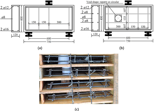
(a) Reinforcement details of beam without openings. (b) Reinforcement details of beams with an opening. (c) Formwork for beams with and without openings (dimensions in mm)
(a) Reinforcement details of beam without openings. (b) Reinforcement details of beams with an opening. (c) Formwork for beams with and without openings (dimensions in mm)
Beam B0 (Figure 2(a)) served as an unstrengthened control specimen without openings and constructed using high-strength concrete (HSC). Beam BF was a strengthened beam without an opening but with a 10 mm thick side-bonded reinforced ECC and one layer of unidirectional, externally bonded CFRP sheets with fibres oriented horizontally (Figure 2(b)). The CFRP sheets were applied on one-half of the beam over its entire depth on both sides of the cross-section. The ECC was reinforced with a galvanised steel welded wire mesh (GSWWM). The remaining four RC deep beams were identical to beam BF beam but had either a circular and square opening, and CFRP sheets were placed above and below the opening, as illustrated in Figures 2(c)–2(f).
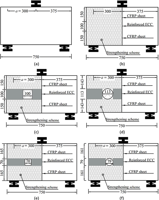
Geometry of test beams: (a) B0; (b) BF; (c) B-rec1; (d) B-cr1; (e) B-rec2; (f) B-cr2 (dimensions in mm)
Geometry of test beams: (a) B0; (b) BF; (c) B-rec1; (d) B-cr1; (e) B-rec2; (f) B-cr2 (dimensions in mm)
The deep beams with openings were categorised into two groups based on the shape and size of the openings.
- ▪
Group 1. Square opening of 100 mm × 100 mm (Figure 2(c)) or circular opening of diameter of 113 mm (Figure 2(d)).
- ▪
Group 2. Square opening of 70 mm × 70 mm (Figure 2(e)) or circular opening of diameter 79 mm (Figure 2(f)).
The specimens with square openings were designated as B-rec1 and B-rec2 for group 1 and group 2, respectively, while the specimens with circular openings were labelled B-cr1 and B-cr2 for group 1 and group 2, respectively. The areas of the circular and square openings were equal or very close to equal. Figure 1(c) shows the formworks for the specimens before concrete casting. Details of all the beams are provided in Table 1.
Beam specifications
| Beam | Shear opening configuration | ||||
|---|---|---|---|---|---|
| Opening shape | Dimensions: mm | Area: mm2 | Opening width/diameter in terms shear span (a) | Strengthening scheme | |
| Group 1 | |||||
| B0 | — | — | — | — | — |
| BF | — | — | — | — | ECC reinforced with GSWWM + external CFRP sheet |
| B-rec1 | Square | 100 mm × 100 mm | 10000 | 0.33a | |
| B-cr1 | Circular | Diameter = 113 mm | 10023 | 0.38a | |
| Group 2 | |||||
| B0 | — | — | — | — | — |
| BF | — | — | — | — | ECC reinforced with GSWWM + external CFRP sheet |
| B-rec2 | Square | 70 mm × 70 mm | 4900 | 0.23a | |
| B-cr2 | Circular | Diameter = 79 mm | 4900 | 0.26a | |
Material properties
Deep beam specimens were fabricated using two distinct concrete mixtures: HSC and ECC. The HSC mixture consisted of Portland cement (grade 52.50 N/mm2), natural sand, crushed limestone aggregates of size 10 mm and water for a designated water-to-binder (w/b) ratio of 0.35. The ECC mixture was made with sand, fly ash, polypropylene (PP) fibres and cement, tailored to achieve a specific compressive strength of 45 N/mm2. The inclusion of fly ash and the absence of coarse aggregate, along with the lower w/b ratio (binder = cement and fly ash) and the addition of PP fibres and high-range water reducer (HRWR) contribute to the distinct properties (highly ductile and crack resistant) of ECCs. The material proportions and mechanical properties of the HSC and ECC mixtures are presented in Tables 2 and 3, respectively. GSWWM (0.75 mm diameter and skewed opening of 12 × 12 mm), available in the Egyptian market, was used to strengthen the 10 mm thick ECC. According to the manufacturer’s technical data, the mechanical properties of the GSWWM were as follows: Young’s modulus of 175 GPa, proof stress of 380 MPa, proof strain of 0.13%, ultimate stress of 580 MPa and ultimate strain of 0.57%.
Mix proportions
| Ingredient: kg/m3 | |||||||
|---|---|---|---|---|---|---|---|
| Cement (grade 52.5R) | Fine aggregate | Coarse aggregate | Fly ash | PP fibre | HRWR: kg/m3 | w/b ratio | |
| HSC | 560 | 565 | 1020 | 125 | — | 18 | 0.35 |
| ECC | 558 | 436 | — | 665 | 20 | 15 | 0.23 |
Concrete properties
| Compression | Tension | |||||
|---|---|---|---|---|---|---|
| Concrete compressive strength, : N/mm2 | Strain at | Maximum strain | Concrete tensile strength, ft: N/mm2 | Strain at ft | Maximum strain | |
| HSC | 88 | 0.0018 | 0.0028 | 2.76 | 0.0002 | 0.0015 |
| ECC | 45 | 0.0031 | 0.005 | 5.92 | 0.022 | 0.038 |
Note: =, ft = concrete tensile strength
The mechanical properties of the CFRP sheets and steel rebars used in this study were specified by the manufacturers and verified through relevant tests. The mechanical properties are documented in Table 4. The woven CFRP sheets were 0.25 mm thick.
Mechanical properties of steel bars and CFRP sheet
| Function of reinforcement | Yield stress, σy: N/mm2 | Yield strain, εy: % | Ultimate stress, σu: N/mm2 | Ultimate strain, εu: % | Modulus of elasticity, E: GPa | |
|---|---|---|---|---|---|---|
| 8 mm bar | Stirrups | 281 | 0.149 | 438 | 12.11 | 188 |
| 12 mm bar | Compression and horizontal steel | 355 | 0.169 | 533 | 12.23 | 210 |
| 16 mm bar | Flexural steel | 363 | 0.174 | 539 | 13.98 | 208 |
| CFRP sheet | External shear strengthening | — | — | 3200 | 1.56 | 210 |
Casting and strengthening preparation
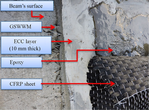
Following concrete curing for 28 days, the outer surfaces of the beams were roughened to ensure proper contact with the ECC layer. Holes were then drilled into the two shear sides of the beam to create anchor points for the strengthening materials (Figure 3(a)). Then, a liquid material was applied to the proposed shear surface for cleaning and priming purposes. Following this, 8 mm shear connectors were embedded into the drilled holes using a chemical epoxy to improve the bond between the existing concrete and the ECC layer, and the GSWWM was applied over the shear zone to reinforce the ECC (Figure 3(b)). A 10 mm thick flowable ECC was cast over the shear zone (Figure 3(c)) to achieve the desired strengthening effect. When the ECC had hardened, a layer of CFRP sheets was applied over the ECC using chemical epoxy (Figure 3(d). An illustration of the shear strengthening to the sides of the tested beams is shown in Figure 4.
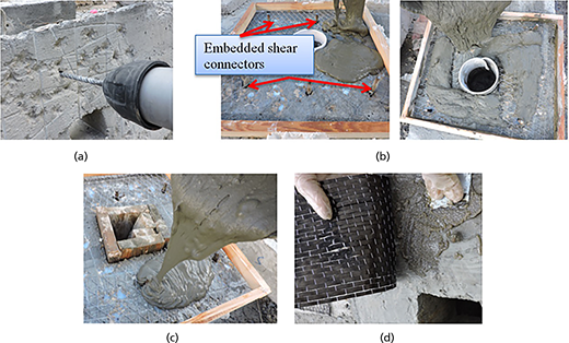
Sequence of shear strengthening implementation: (a) roughening and perforation; (b) casting of ECC for beams with circular opening; (c) casting of ECC for beams with rectangular opening; (d) bonding of CFRP sheets to ECC surface
Sequence of shear strengthening implementation: (a) roughening and perforation; (b) casting of ECC for beams with circular opening; (c) casting of ECC for beams with rectangular opening; (d) bonding of CFRP sheets to ECC surface
Test setup and procedure
Experiments were conducted in a testing machine at Kafr El-Sheikh University (Figure 5). The concrete specimens were prepared for testing through a three-step process: cleaning, application of white paint and careful positioning in the testing machine with an overhead crane. The white paint coating facilitated visual observation and documentation of cracking patterns and failure modes during testing through photographs. The hydraulic machine could exert forces up to 2500 kN on each deep beam.
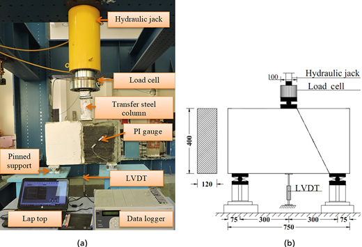
The test setup consisted of a hinged support at one extremity of the beam and a roller support at the other, creating an effective span of 600 mm. A linear variable displacement transducer (LVDT) was positioned at midspan to record deflection measurements (Figure 5). The concrete beams were subjected to incremental loading in steps of 5 kN. At each load stage, cracks were marked for reference, photographed for documentation and deflection readings were logged electronically.
Test results and discussion
Cracking and failure modes
Control beam B0 (an unstrengthened deep beam without openings) exhibited a diagonal cracking pattern on the beam side with 300 mm spacing between stirrups, indicative of a shear failure mode and bearing failure mechanism, as illustrated in Figure 6(a). This failure mode is typical for simply supported deep beams, and consistent with the typical behaviour reported in prior studies (Mansour and El-Maaddawy, 2021). The high shear stresses developed within the beam led to the formation of shear splitting cracks along the diagonal compression strut between the support and load location.
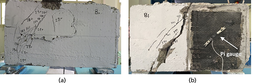
The strengthened control beam (BF) exhibited a shear failure mode on the half with a 150 mm stirrup spacing where the strengthening system was not applied, as shown in Figure 6(b). Although the other half of the deep beam had a 300 mm stirrup spacing, the hybrid ECC–CFRP strengthening increased the shear capacity beyond that of the side with a 150 mm stirrup spacing. The wider stirrup spacing in this area ensured that the shear stresses were primarily resisted by the concrete and the ECC–CFRP system, as intended. On the contrary, the other half of the beam, which lacked the additional shear reinforcement provided by the strengthening system, remained vulnerable to shear stresses.
For the deep beam specimens with openings, the observed failure modes were as follows.
- ▪
Beam B-rec1 (100 mm × 100 mm square opening). As shown in Figure 7(a), this beam showed diagonal cracks between the opening and the support on the side with the hybrid ECC–CFRP strengthening. A major diagonal shear crack existed on the side of the square opening and passed through the top corner of the opening, creating signs of concrete crushing. As expected, the square opening made the developed diagonal deviate from the normal path between the load location and the support, as noted in specimens B0 and BF. Additionally, deterioration was observed at the two opposite corners of the opening, which could be attributed to stress concentrations and potential bearing failures at these locations. One may conclude that the square opening likely disrupted the load-transfer mechanism, leading to localised failures near the opening.
- ▪
Beam B-cr1 (113 mm dia. circular opening). This deep beam exhibited hairline inclined cracks around the circular opening, suggesting a different crack propagation pattern than that for the square opening (Figure 7(b)). At the same loading stage, shear cracks were also generated in the unstrengthened half with a stirrup spacing of 150 mm. It is believed that the circular shape of the larger opening allowed for a greater shear capacity of the strengthened side, to the extent that the shear failure occurred in the unstrengthened part with the 150 mm stirrup spacing.
- ▪
Beam B-rec2 (70 mm × 70 mm square opening). Diagonal shear cracks were generated between the opening and the support and between the opening and the loading point. However, no deterioration was observed around this smaller square opening (Figure 7(c)), unlike the specimen with the larger square opening (Figure 7(a)). Additionally, shear cracks were generated in the unstrengthened half with a stirrup spacing of 150 mm. However, these shear cracks occurred after the shear cracks were generated beside the opening. The failure mode of B-rec2 is thought to be different from that of B-rec1 owing to the smaller size of the square opening, which had less impact on the load-transfer mechanism.
- ▪
Beam B-cr2 (79 mm dia. circular opening). Shear cracks were generated in the unstrengthened half of the beam with a stirrup spacing of 150 mm. However, neither diagonal shear cracks nor deterioration were detected around the smaller circular opening (Figure 7(d)). The failure mode of B-cr2 is believed to be different from that of B-cr1 owing to the smaller size of the circular opening, which may have allowed for a more effective load transfer compared with the larger opening in B-cr1.
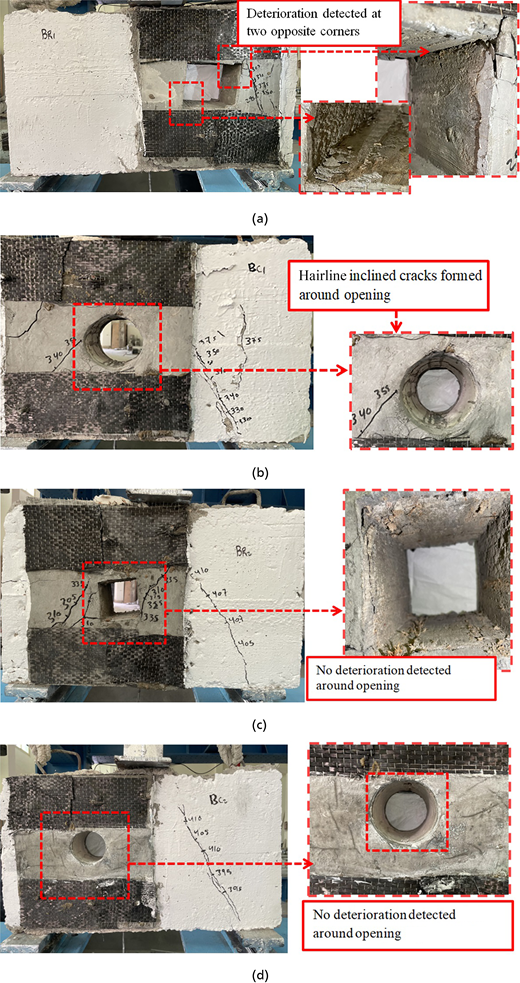
Crack pattern and failure modes of strengthened deep beams with opening: (a) B-rec1; (b) B-cr1; (c) B-rec2; (d) B-cr2
Crack pattern and failure modes of strengthened deep beams with opening: (a) B-rec1; (b) B-cr1; (c) B-rec2; (d) B-cr2
The failure modes of the beams were thus influenced by the shape and size of the openings, as well as the presence and location of the strengthening system. The larger openings (specimens B-rec1 and B-cr1) appeared to have a more significant impact on the load-transfer mechanism, resulting in localised failures and crack patterns around the openings themselves. In contrast, the smaller openings (specimens B-rec2 and B-cr2) seemed to have less effect on the overall failure mode, with shear cracking occurring primarily in the unstrengthened regions. As expected, the specimens with circular openings (B-cr1 and B-cr2) exhibited different crack propagation patterns than the specimens with square openings, potentially owing to the influence of the opening shape on stress distributions and load-transfer mechanisms.
The test results are presented in Table 5, from which a few key observations can be made regarding the ultimate capacity, absorbed energy and stiffness of the different beam specimens. For all the specimens with openings (B-rec1, B-cr1, B-rec2 and B-cr2), the ultimate load-carrying capacity (Pu) was greater than that of the control beam without an opening (B0). Specifically, the increase in ultimate capacity compared with the control beam was 33% for B-rec1, 33% for B-cr1, 44% for B-rec2 and 47% for B-cr2. These results suggest that the presence of an opening in the deep beams did not decrease their load-carrying capacity when strengthened using a combination of ECC and CFRP sheets applied at the top and bottom of the opening.
Test results
| Beam | Ultimate stage | Absorbed energy, E | Stiffness, K | Mode of failurea | ||||
|---|---|---|---|---|---|---|---|---|
| Pu: kN | Gain: % | Δu: mm | E: kN.mm | E/EB0 | K: kN/mm | K/KB0 | ||
| Group 1 | ||||||||
| B0 | 283 | — | 4.36 | 825 | 1.00 | 89 | 1.00 | S + B |
| BF | 424 | 49 | 2.90 | 1774 | 2.15 | 182 | 2.04 | S |
| B-rec1 | 377 | 33 | 4.02 | 1943 | 2.35 | 117 | 1.31 | S |
| B-cr1 | 376 | 33 | 2.93 | 2334 | 2.83 | 133 | 1.49 | S |
| Group 2 | ||||||||
| B0 | 283 | — | 4.36 | 825 | 1.00 | 89 | 1.00 | S + B |
| BF | 424 | 49 | 2.90 | 1774 | 2.15 | 182 | 2.04 | S |
| B-rec2 | 409 | 44 | 3.58 | 2679 | 3.25 | 137 | 1.54 | S |
| B-cr2 | 416 | 47 | 4.54 | 3287 | 3.98 | 137 | 1.54 | S |
S = shear failure; B = bearing failure
Additionally, it can be observed that specimens B-rec2 and B-cr2, with smaller openings, exhibited greater ultimate shear capacity than specimens B-rec1 and B-cr1 with larger openings (by 8.5% and 10.6%, respectively). This finding indicates that the size of the opening has an effect on shear capacity, with a smaller opening leading to an increase in the ultimate shear capacity of deep beam compared with a larger opening.
Comparing the strengthened deep beams with openings (B-rec1, B-cr1, B-rec2 and B-cr2) to the strengthened deep beam without an opening (BF), the ultimate shear capacity of beam BF was greater than those of the strengthened beams with an opening. This is attributed to the fact that the CFRP strengthening was applied over the entire beam depth for BF, while it was applied only above and below the opening in the other beams. The results in Table 5 also show that the specimens with openings generally exhibited higher absorbed energy (E) and stiffness (K) than the control beam (B0), indicating improved ductility and overall structural performance owing to the ECC–CFRP strengthening system.
In summary, the test results demonstrate that using the ECC–CFRP strengthening technique effectively mitigated the potential reduction in shear capacity caused by openings in deep beams. Furthermore, smaller opening sizes resulted in a smaller decrease in ultimate shear capacity compared with larger openings, highlighting the importance of optimising the opening size when designing such structural elements.
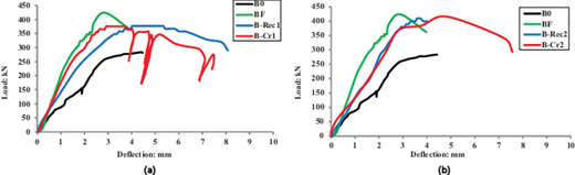
Load–deflection curves and absorbed energy
The midspan deflection of the concrete deep beams during loading was recorded by the LVDT and the load–deflection curves are shown in Figure 8. The peak deflections (Δu) are listed in Table 5. As shown in Figure 8, control beam B0 initially behaved elastically until cracking (linear response). Then, it underwent plastic deformation and hardening until the peak load, experiencing abrupt failure afterwards. The strengthened deep beams demonstrated superior load capacity and ductility compared with B0. These beams exhibited extended hardening beyond cracking before failing. Table 5 shows that the strengthening method substantially increased energy absorption, with values ranging from 34% to 380% compared with B0.
Numerical simulation
Finite-element (FE) modelling plays a crucial role in numerical investigations of structural performance under increasing load to collapse. Non-linear three-dimensional FE analysis was conducted using Abaqus to model the structural behaviour of the tested deep beams. To ensure the reliability and accuracy of the results, the numerical data obtained from all the modelled specimens underwent rigorous validation by comparison with the experimental observations. Through the application of FE modelling, this research achieved a detailed understanding of the performance characteristics of deep beams reinforced with ECC and CFRP sheets.
The concrete damaged plasticity (CDP) model in Abaqus was employed in this study owing to its proven ability to simulate the complex behaviour of concrete. The CDP model combines plasticity formulations for modelling the inelastic behaviour of concrete under compression and damage mechanics to represent the degradation of elastic stiffness induced by cracking in tension. This combined approach enables the CDP model to accurately capture the non-linear stress–strain response of concrete under arbitrary loading conditions. The widespread adoption and successful implementations of the CDP model for non-linear analysis of concrete structures across numerous studies have validated its capability and flexibility as an advanced constitutive model (Barros and Figueiras, 1999; Carreira and Chu, 1985; Nataraja et al., 1999).
Defining the stress–strain relationship for concrete is critical for accurate material modelling. To quantify this behaviour, experimental testing was conducted, including splitting tensile and compressive strength tests on concrete samples, as shown in Table 3. The key parameters used for the CDP model were based on the work of Carreira and Chu (1985), as illustrated in Figures 9(a) and 9(b). As recommended in previous studies (Hamoda and Hossain, 2019; Hamoda et al., 2021; Jin et al., 2022; Lee and Fenves, 1998; Lubliner et al., 1989), the dilation angle (ψ), viscosity relaxation parameter (μ), eccentricity (e), ratio of biaxial to uniaxial compressive yield stresses and the ratio of the second stress invariant on the tensile to the compressive meridian were chosen as 35°, 0, 0.1, 1.16 and 0.66, respectively.
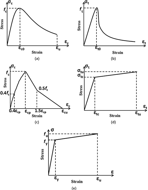
Stress–strain curves: (a) concrete in compression (Carreira and Chu, 1985); (b) concrete in tension (Carreira and Chu, 1985); (c) ECC in compression (Zhou et al., 2015); (d) ECC in tension (Zhou et al., 2015); (e) steel
Stress–strain curves: (a) concrete in compression (Carreira and Chu, 1985); (b) concrete in tension (Carreira and Chu, 1985); (c) ECC in compression (Zhou et al., 2015); (d) ECC in tension (Zhou et al., 2015); (e) steel
For the ECC material, the stress–strain curve was based on the work done by Zhou et al. (2015), as shown in Figures 9(c) and 9(d).
Steel material behaviour was modelled using a two-step material definition to capture both the elastic and plastic responses. This approach involved defining an initial elastic stage followed by a plastic hardening rule. Firstly, elastic properties such as Young’s modulus and Poisson’s ratio were specified. Subsequently, a hardening rule was defined to describe the material’s plastic behaviour after exceeding the elastic limit, as shown in Figure 9(e).
In the Abaqus FEM (Figure 10(a)), the HSC, ECC, loading plate and supporting plate were modelled using solid elements (C3D8R), while the reinforcement and stirrups were modelled using truss elements (T3D2). Four-node quadrilateral shell elements with reduced integration (S4R) were employed to simulate the response of the CFRP sheets used for shear strengthening.
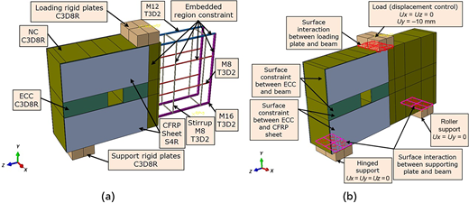
Embedded region constraints available in Abaqus were employed to accurately capture the interaction between the concrete and the reinforcing bars and stirrups. In this approach, the concrete was designated as the host region, and the vertical reinforcing bars and stirrups were defined as embedded elements within the concrete (Figure 10(a)).
The interface behaviour between the HSC and the ECC and between the ECC and CFRP sheet was represented using surface-to-surface constraints. Additionally, a surface-to-surface contact interaction property was utilised to model the interface behaviour between the HSC and both the loading and support plates. This contact interaction imposed a hard pressure-overclosure behaviour in the normal direction. In contrast, the tangential interactions were governed by the Coulomb friction model, implementing a friction coefficient of 0.25 as recommended in the literature (Jin et al., 2022). The boundary conditions are illustrated in Figure 10(b).
The Abaqus model replicated the three-point loading setup from the experiments, as shown in Figure 10(b). Coupling constraints were employed to connect the reference points to the loading and supporting plates, where the applied loads and boundary conditions were introduced. Specifically, a vertical downward displacement equal to 10 mm was applied at the reference point of the upper loading plate to simulate the experimental loading procedure.
Validation of the FEM
The FEM was rigorously validated against the experimental findings to ensure its accuracy and reliability in predicting the behaviour of deep beams reinforced with ECC and CFRP sheets. A comparison of the predicted failure modes and the observed experimental results demonstrated excellent agreement, thus providing confidence in the numerical simulations.
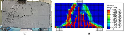
For control beam B0, both the observed and predicted crack patterns showed a major diagonal cracking pattern in the zone with a stirrup spacing of 300 mm, accompanied by minor cracks in the zone with a tighter stirrup spacing of 150 mm, as depicted in Figure 11. This behaviour aligns with the expected shear failure mode typically observed in deep beams without strengthening schemes.
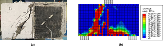
In the case of beam BF, which was strengthened with ECC-CFRP layers on one side, the FEM accurately captured the observed shear failure mode width diagonal splitting crack in the unstrengthened zone with a stirrup spacing of 150 mm, as depicted in Figure 12. This failure in the unstrengthened region was consistent with the experimental observations, highlighting the effectiveness of the strengthening system in enhancing the shear resistance on the strengthened side.
For the beams with openings, it is essential to note that shear distortions were noticed in the strengthened layers during the experiments. However, the underlying crack patterns were obscured by the CFRP layers. In Figures 13 and 14, the CFRP layers were hidden in the FEM contours to facilitate a more comprehensive comparison, revealing the cracks within the ECC layer.
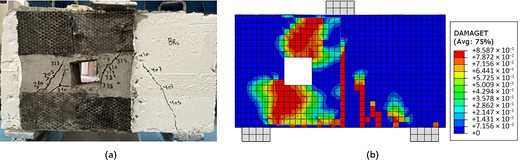
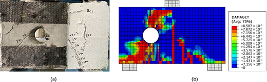
Beams B-rec1 and B-cr1 beams, with the larger square and circular openings, exhibited failure around the openings that extended towards the loading and supporting plates, with less intensive shear cracks in the unstrengthened zones. While some of these cracks were visible in the experimental observations, the distortions in the strengthened layers indicated the presence of cracks between the openings and the loading and supporting plates. The FEM results shown in Figures 13 and 14 provided a more detailed and comprehensive representation of the crack propagation patterns, as the CFRP layers were removed from the visualisation, exposing the underlying cracks within the ECC layer. This enhanced visibility offered by the numerical simulations allowed for a clearer understanding of the crack propagation mechanisms in the beams, further emphasising the significance of FEMs in obtaining a more comprehensive picture of structural behaviour. Notably, the FEM accurately captured the observed failure modes and crack patterns, validating its ability to reliably simulate the complex behaviour of deep beams reinforced with ECC and CFRP sheets.
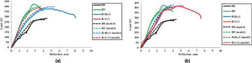
Validation of the FEM was further strengthened by the remarkable agreement between the experimental and numerical load–deflection responses, as shown in Table 6 and Figure 15. The average ratios of the FEM predictions to the experimental data for ultimate loads and corresponding deflections were 0.99 and 0.94, respectively, with low coefficients of variation (CoV) of 0.045 and 0.059 (Table 6). These ratios, close to unity, demonstrate the high accuracy of the FEM in predicting the ultimate load-carrying capacity and the associated deflections of the deep beam specimens. Moreover, comparison of the experimental and FEM load–displacement behaviours revealed close agreement up to the ultimate load levels, further validating the model's ability to capture the overall structural response accurately. Notably, the FEM simulated the initial linear elastic response with high precision, indicating its effectiveness in modelling the early stages of the load–deflection behaviour before the onset of non-linear effects. The strong correlation between the numerical and experimental results, coupled with the low variability in the prediction ratios, ensured the reliability of the proposed FEM for analysing the behaviour of deep beams reinforced with ECC and CFRP sheets.
Experimental and numerical ultimate capacities
| Beam | Ultimate capacity, Pu | Ultimate deflection, Δu | ||||
|---|---|---|---|---|---|---|
| Pu,exp: kN | Pu,FEM: kN | Pu,exp/Pu,FEM | Δu,exp: mm | Δu,FEM: mm | Δu,exp/Δu,FEM | |
| B0 | 283 | 271.44 | 1.04 | 4.36 | 4.27 | 1.02 |
| BF | 424 | 402.52 | 1.052 | 2.90 | 3.13 | 0.93 |
| B-rec1 | 377 | 397.36 | 0.948 | 4.02 | 4.22 | 0.95 |
| B-cr1 | 376 | 386.01 | 0.97 | 2.93 | 3.29 | 0.89 |
| B-rec2 | 409 | 427.53 | 0.96 | 3.58 | 4.08 | 0.88 |
| B-cr2 | 416 | 419.65 | 0.99 | 4.54 | 4.59 | 0.99 |
| Mean | 0.99 | Mean | 0.94 | |||
| SD | 0.044 | SD | 0.056 | |||
| CoV: % | 0.045 | CoV: % | 0.059 | |||
| Error: % | 5 | Error: % | 14 | |||
Parametric study
With the FEM verified, a parametric study was conducted to study the effect of the presence and amount of ECC layers and CFRP sheets on the ultimate load-carrying capacity of the deep beam with the larger square opening (B-rec1). The ECC layer thickness was taken as 5, 10, 15 and 20 mm, while the number of the CFRP layers was taken 1, 2, 3 and 4. The numerical findings are summarised in Figure 16 and Table 7. The control unstrengthened deep beam with no opening (B0) was found to have an ultimate load of 271 kN (Table 6). The ultimate load was reduced to 190 kN (Table 7) when a 100 mm × 100 mm square opening existed in the beam (a reduction of 30%). Table 7 shows that the ultimate capacity of the deep beam with an opening increased by 58%, 84%, 95% and 100% with, respectively, 1, 2, 3 and 4 CFRP layers, compared with the unstrengthened beam with square opening. The ultimate capacities increased were by 26%, 109%, 123%, 124% and 125% with the addition of a 10 mm thick ECC layer along with 0, 1, 2, 3 and 4 CFRP layers, respectively, compared with the unstrengthened beam with a square opening (BF).
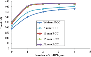
Effect of thickness of ECC and number of CFRP layers on the ultimate load capacity of deep beam with 100 mm × 100 mm square opening (B-rec1)
Effect of thickness of ECC and number of CFRP layers on the ultimate load capacity of deep beam with 100 mm × 100 mm square opening (B-rec1)
Effect of the presence of ECC and CFRP layers on the ultimate load the capacity of deep beam with 100 mm × 100 mm square opening (B-rec1)
| ECC thickness: mm | Ultimate load capacity, Pu: kN | ||||
|---|---|---|---|---|---|
| Number of CFRP layers | |||||
| 0 | 1 | 2 | 3 | 4 | |
| No ECC layer | 190 | 300 | 350 | 370 | 380 |
| 5 | 218 | 344 | 379 | 392 | 402 |
| 10 | 240 | 397 | 425 | 426 | 428 |
| 15 | 250 | 400 | 428 | 428 | 428 |
| 20 | 256 | 405 | 428 | 428 | 428 |
To reach the original capacity of B0 (271 kN), using a 20 mm thick ECC layer was not enough to accommodate a square opening as the corresponding ultimate capacity was only 256 kN. On the other hand, using one CFRP layer without the ECC layer led to an ultimate capacity of 300 kN, which was enough to bring the capacity of the beam with a square opening to more than that of the unstrengthened beam with no opening.
An increase in the thickness of the ECC layer increased the ultimate capacity of the deep beam with the larger square opening. Although Table 7 shows that increasing both the ECC layer thickness and the number of the CFRP layers increased the ultimate capacity, an insignificant increase was observed for ECC layer thickness beyond 10 mm and a number of CFRP layers beyond one. This is attributed to the fact that an increase in the amount of strengthening around a square opening shifts the shear failure from the opening side to the other side of the beam, which was without both opening and strengthening. The capacity of this other side was dependent on the capacity of both the concrete and the steel stirrups, which were identical in all specimens. As shown in Table 7, the greatest capacity was 428 kN. Based on the numerical findings of this example, it may be concluded that the verified FEM was capable of providing the optimum design with respect to the proper thickness of the ECC layer and the associated number of CFRP layers to bring the capacity of the beam with an opening to that without an opening.
Conclusions
The effectiveness of a novel strengthening technique that combines ECC reinforced with GSWWM and externally bonded CFRP sheets for enhancing the shear strength of simply supported deep beams with openings was investigated. Through a comprehensive experimental programme and advanced FE modelling, the key outcomes of this work are as follows.
- (a)
The proposed hybrid strengthening approach, incorporating reinforced ECC and externally bonded CFRP sheets, effectively mitigated the reduction in shear capacity caused by the presence of openings in deep beams. Specimens strengthened with this technique exhibited higher ultimate load-carrying capacities than unstrengthened control beams.
- (b)
The shape and size of the openings influenced the extent of shear capacity reduction and the observed failure modes. Smaller openings generally resulted in a smaller decrease in ultimate shear capacity compared with larger openings. Additionally, circular openings exhibited different crack propagation patterns than square openings owing to the influence of the shape of the opening on stress distributions and load-transfer mechanisms.
- (c)
A FEM, developed using Abaqus and employing the CDP model, accurately predicted the failure modes, crack patterns and load–deflection responses observed in the experimental programme. The strong agreement between the numerical simulations and experimental results validated the reliability and predictive capabilities of the FEM.
- (d)
The FEM provided a detailed representation of crack propagation patterns, offering insights into the underlying mechanisms that were not fully captured by the experimental observations alone. This enhanced visibility into structural behaviour highlights the significance of numerical simulations in complementing experimental studies.
- (e)
The proposed hybrid strengthening technique effectively improved the ductility, energy dissipation capacity and overall structural performance of deep beams with openings, as evidenced by the increased absorbed energy and stiffness observed in strengthened beams compared with unstrengthened beams.
The findings from this research provide valuable guidelines for the practical implementation of this hybrid strengthening technique. Combining reinforced ECCs and externally bonded CFRP sheets offers a promising solution for enhancing the shear capacity and overall performance of deep beams with openings, addressing a critical need in various construction projects.
Acknowledgements
The co-authors would like to acknowledge the first author for personally funding this research project. The authors are extremely grateful for use of the laboratory at Kafrelsheikh University for the tests. The authors would also like to thank the researchers of King Saud University in Riyadh, Saudi Arabia, for their invaluable support under project number RSP2024R343.
