


This paper proposes an approach for the development of a dynamic maintenance policy for the railway rolling stock system considering the dynamic characteristics of the system, the operation environment, and the maintenance process. The proposed approach can also be applied to other similar complex technical systems.
This study explores the state-of-the-art in dynamic maintenance policy development for railway rolling stock to identify the research gap. The proposed approach is demonstrated through a case study on dynamic maintenance policy development for railway rolling stock maintenance support planning, emphasising constant assessment and improvement in the maintenance policy.
This study emphasises on the need for an effective, efficient, and dynamic maintenance policy that adapts to evolving system requirements such as organisational contexts, technological advancements, and regulatory requirements. This study finds that there are specific dynamic characteristics in each step of the maintenance policy development process. These dynamic characteristics are dependent on the changes in system requirements, the environment and in the maintenance process. The proposed approach for dynamic maintenance policy development provides a framework for the identification of these dynamic characteristics for different complex technical systems operating in a specific context.
Despite the significant impact of railway rolling stock maintenance on railway system availability, research in this area is limited. The proposed approach for maintenance policy development for rolling stock integrates adaptability and responsiveness to dynamic factors in the maintenance process and the system requirements. Thus, the proposed approach provides a guide for industry professionals and directions for future research in dynamic maintenance policy development for other similar complex technical systems.
1. Introduction
An effective and efficient maintenance policy plays a pivotal role in ensuring the availability of a complex technical system. An optimised maintenance policy may reflect the conditions of a system when it was designed. However, there is a continuous evolution of system dynamics in complex systems that are influenced by factors such as shifting operational requirements, changing system configuration, and technological developments. These dynamics make static maintenance policy obsolete over time. Complex technical systems require an evolving maintenance policy throughout their lifecycle to enhance maintenance effectiveness. A dynamic maintenance policy is based on considerations from system design as well as, alignment with changing system requirements, operating environments, and constraints, during the operation and maintenance phase.
Changes in system requirements lead to modifications in maintenance processes, subsequently influencing the demand for maintenance and maintenance support, and consequently impacting the maintenance policy. When maintenance is perceived as a value-added process it can emphasise organisational goals such as corporate sustainability, and wider economic social, and environmental imperatives (Liyanage and Kumar, 2003). To emphasise and be aligned to organisational goals, the maintenance policy of an organisation must be dynamic, adaptive, and responsive to the system requirements, organisational goals, and technological factors.
The measurement of the performance of an existing maintenance policy is complex when it comes to linking the performance indicators at the operational level and strategic level (Parida and Kumar, 2006). The maintenance policy must be assessed against the achievement of strategic business objectives using qualitative and quantitative approaches to maintenance such as RAMS (reliability, availability, maintainability, safety), LCC (Life-cycle costing), TPM (total productive maintenance), OEE (overall equipment effectiveness) etc.; (Kumar et al., 2013; Parida et al., 2015; Parida and Kumar, 2009).
Railway rolling stock is a complex technical system with dynamic system requirements and operational conditions. Enhancing rolling stock reliability involves integrating stakeholder data, effectively utilising the collected information, and ensuring responsive and efficient maintenance management (Hakim and Kusumah, 2022). Leveraging data-driven maintenance decisions, which integrate input from various stakeholders, can significantly enhance rolling stock fleet reliability, particularly when the maintenance strategy adopts a dynamic approach that combines preventive and predictive maintenance strategies (del Castillo et al., 2023).
The development of a dynamic maintenance policy is expected to address several challenges related to the maintenance of the railway rolling stock fleet. Trains are designed to operate for 30–40 years, and during their lifetime, the rolling stock system has different maintenance needs for optimal operation, emphasising the need for reactive maintenance based on dynamic thresholds (Turgis et al., 2021). The most significant factors influencing rolling stock maintenance involve the dynamic aspects of the inventory supply chain, the necessity for knowledge and competency development, and the equipment selection for maintenance and maintenance support, all of which are integral components of the maintenance policy (Idris et al., 2023). Maintenance management and scheduling also require consideration of dynamic aspects such as the unavailability of rolling stock on the scheduled maintenance due to operational requirements or unplanned in-service failures (Louadah et al., 2024). These challenges emphasise the need for a dynamic maintenance policy that reflects changing system requirements, operational conditions, and maintenance needs for railway rolling stock.
To facilitate the development of a dynamic maintenance policy for railway rolling stock, this research seeks to address a fundamental question: How can we integrate the dynamics of the railway rolling stock system, its operational conditions, and maintenance processes into the formulation of a dynamic maintenance policy? Within this overarching inquiry, the research pursues two specific objectives: (1) To determine the essential parameters crucial for the development of the maintenance policy, and (2) To establish the optimal frequency for updating these parameters to ensure that the maintenance policy remains aligned with the evolving system requirements. By addressing these objectives, the research aims to devise a maintenance policy that effectively adapts to the dynamic nature of railway rolling stock that is aligned to system requirements and organisational goals.
To answer the above-stated research question, a holistic and systematic approach to dynamic maintenance policy development has been proposed in this research. This approach integrates the considerations of rolling stock system requirements, operational contexts, and maintenance processes. The theoretical framework for the development of this approach is based on structured and semi-structured interviews with domain experts in the maintenance of railway rolling stock in Sweden, a systematic literature survey on maintenance policies in general and maintenance of rolling stock in particular, and reference to best practices and international standards on asset management, and dependability management.
The proposed approach for dynamic maintenance policy development has been implemented to plan maintenance and maintenance support for heavy maintenance actions on high-value components like engines, compressors, and braking systems for a fleet of railway rolling stock. This implementation provides a roadmap on how a dynamic maintenance policy can be developed for a multi-stakeholder environment including resource dependencies created by aspects of fleet management of railway rolling stock. The implementation also demonstrates how and why is it essential to consider dynamic aspects in maintenance policy for complex technical systems. Overall, this research provides practical guidance for improving the reliability and availability performance of railway rolling stock systems through the adoption of a dynamic maintenance policy.
2. Methodology
This research is based on three analytical research approaches, i.e. (1) literature survey, (2) study of standards related to asset management and maintenance, (3) case study in the maintenance of high-value components for railway rolling stock fleet.
A literature review serves as the basis for the development of new knowledge and the identification of new research areas (Webster and Watson, 2002). In this research, a literature review has been used to identify the challenges in the development of a dynamic maintenance policy in general and the development of a dynamic maintenance policy for railway rolling stock in particular. The keywords used for the literature review were, “maintenance policy”, “maintenance strategy”, “maintenance concept”, “railway rolling stock”, “asset management strategy”, “maintenance challenges”, and “dynamic maintenance policy”. These keywords were combined using “AND”, “OR” operators to refine the search results. Synonyms of the keywords such as railway vehicle, and railway fleet, were also considered to refine the search results. To ensure the inclusion of high-quality research, peer-reviewed journal articles, conference proceedings, and academic dissertations were included. The research articles that were not specifically focused on the maintenance of rolling stock, were limited to the maintenance of industrial systems. The keywords were searched in the title of published articles. Articles published after the year 2020 were given priority, so that new research challenges and areas can be identified.
The approach for maintenance policy development is adapted from Dependability Management, Part 3–14: Application Guide, Maintenance, and Maintenance support (IEC, 2004). The international standard on dependability management provides a general approach to maintenance and maintenance support with a focus on complex systems. It addresses the case of complex systems in the context of adjustment of maintenance and maintenance support to specific situations during the design phase as well as the operation and maintenance phase. The framework for consideration of railway system requirements has been based on International standard ISO55001, Asset management-management system requirements, guidelines for applications (SS-ISO 55002, 2018). This standard was used to adopt a structured approach for consideration to context of the railway organisation, and the alignment of maintenance policy to organisational objectives. The UIC Railway Application Guide that provides practical implementation of Asset management through ISO 55001 was also referred (UIC, 2016). The guidelines provided by the UIC railway application guide, were used to identify the need and benefits of utilising asset management concepts for the railway system.
The case study research method is known to provide in-depth insights into complex phenomena within real-life contexts (Yin, 2018). The case study method was used in this research to develop insights into the complex process of dynamic maintenance policy development with the help of a real-world case study. The case study used in this research is on the maintenance policy development for high-value components for railway rolling stock in Sweden. This project was executed as part of the ‘AI factory for Railways' project (Karim et al., 2023). The data sources used in this project were obtained from vehicle owners, operators, and maintenance service providers. Several semi-structured and unstructured interviews with railway stakeholders were conducted to identify the needs and requirements for the maintenance plan for rolling stock. The data sources as shown in Figure 1 were received from various stakeholders for railway rolling stock in Sweden. These data sources were integrated to develop a holistic maintenance plan. The process of the development of this real-world maintenance support plan formed the foundation for the identification of the dynamic elements in the maintenance policy development process. Apart from this major case study, a few minor case studies with semi-structured and unstructured interviews with industry participants responsible for operation and maintenance in the mining, aviation, and construction industries were also considered.
 The first box is titled “Preventive maintenance plan” and contains two header cells labeled “P K” and “Fleet name”, followed by entries: “Component Description”, “P M action”, “P M interval K M”, “P M interval month”, and “P M interval days”. The second box is titled “Operation Prognosis” with header cells “P K” and “Fleet name”, followed by entries: “Fleet Name”, “Operation prognosis per year”, “Vehicle owner”, and “Vehicle operator”. The third box is titled “High value component configuration” with header cells “P K” and “Article number”, followed by entries: “Fleet name”, “Vehicle number”, and “Component description”. The fourth box is titled “Vehicle configuration” with header cells “P K” and “Fleet name”, followed by entries: “Vehicle number”, “Fleet NAme”, “Wagon number”, “E V N Code”, “Vehicle owner”, “Vehicle operator”, and “Maintenance provider”. The fifth box is titled “Preventive maintenance history” with header cells “P K” and “Artcl n r. + I D n r.”, followed by entries: “Article number”, “I D number”, “P M date”, “P M action”, and “P M interval days”.
Data sources for maintenance support planning of high value components
The first box is titled “Preventive maintenance plan” and contains two header cells labeled “P K” and “Fleet name”, followed by entries: “Component Description”, “P M action”, “P M interval K M”, “P M interval month”, and “P M interval days”. The second box is titled “Operation Prognosis” with header cells “P K” and “Fleet name”, followed by entries: “Fleet Name”, “Operation prognosis per year”, “Vehicle owner”, and “Vehicle operator”. The third box is titled “High value component configuration” with header cells “P K” and “Article number”, followed by entries: “Fleet name”, “Vehicle number”, and “Component description”. The fourth box is titled “Vehicle configuration” with header cells “P K” and “Fleet name”, followed by entries: “Vehicle number”, “Fleet NAme”, “Wagon number”, “E V N Code”, “Vehicle owner”, “Vehicle operator”, and “Maintenance provider”. The fifth box is titled “Preventive maintenance history” with header cells “P K” and “Artcl n r. + I D n r.”, followed by entries: “Article number”, “I D number”, “P M date”, “P M action”, and “P M interval days”.Data sources for maintenance support planning of high value components
3. Theoretical framework
3.1 Literature survey and gap analysis
3.1.1 Issues and challenges in maintenance of railway rolling stock
More specifically, when the maintenance of rolling stock is considered, there are a number of unique challenges that are encountered, such as those related to the cross-organisational operation and maintenance, organisational structure, context-aware analytics, fleet and individual vehicle maintenance, change management, sharing of the pool of high-value components, and the complex technical system-of systems configuration of the rolling stock system (Kumari, 2022).
The lack of proper, timely, and inaccurate maintenance of rolling stock may lead to decreased operational performance or even safety challenges with respect to the whole railway system, such as derailments (Chatzimichailidou et al., 2018). The lack of ability to adjust maintenance management programs for rolling stock, to factors such as operational schedules, fleet performance based on the lifecycle stage of the fleet, maintenance echelons, and maintenance support services, may result in decreased overall performance of the railway system (Weiss, 2013). Management of spare parts forms an important part of maintenance support and hence, maintenance policy for rolling stock. It was observed that of the highest influential costs for maintenance in rolling stock are 13.8% for spare parts, 11% for life cycle cost, 6.4% for preventive maintenance, and 4.6% each for workforce, corrective maintenance, and cost of ownership (Idris et al., 2022).
3.1.2 Dynamic maintenance policy
A dynamic maintenance policy for systems with repairable components to reflect the current initial age of the components at the time of inspection was proposed using a reliability and maintenance model (Yousefi et al., 2020). Maintenance policy optimisation for a multi-components system considering the characteristics of a dynamic environment was based on a diagnostic probability threshold as a condition for preventive action (Misaii, 2022). A maintenance policy analysis for a multi-unit system that considers not only the dynamic states of the components but also the inter-relationship among the states was developed to address the issue of gradual performance degradation in multi-unit systems (Lee, 2020).
Another approach for a maintenance policy for a multi-component system has been proposed, that considers the dependence between components and their dynamic importance based on their degradation and reliability (Zhang et al., 2022). There are some more studies related to the development of a dynamic maintenance policy for different multi-component, multi-state, complex systems working under varying operational contexts, that are focussed on capturing the dynamicity in the degradation of a single component or a group of components in the systems (Khoury et al., 2011; Liu, 2015; Gupta et al., 2005; Gen-bao et al., 2013).
An optimum condition-based maintenance policy with dynamic inspections to reduce the life cycle cost through reducing the number of inspections based on the asset condition was proposed (Cheng et al., 2022). A dynamic update of degradation parameters using to predict remaining useful life and time between two successive inspections, has been used to develop a dynamic auto-adaptive maintenance policy (Omshi et al., 2020). A dynamic condition-based maintenance policy was developed to enable the dynamic revision of optimal preventive maintenance threshold for heterogeneous degradation rate of components (Lu and Luo, 2024).
A dynamic grouping of scheduled maintenance actions of each component for road infrastructure, to ensure proper functioning of the system and to minimise maintenance cost, has been proposed (Najeh et al., 2021). A dynamic inspection and maintenance scheduling for a multi-state system using decision epochs to reduce inspection and maintenance costs was developed to optimise maintenance policy (Chen et al., 2023). Data-driven predictive maintenance policy has been proposed to obtain a continuous probability distribution of system states dynamically to predict the remaining useful life and make maintenance decisions (Xie et al., 2023).
An approach for dynamic scheduling of preventive maintenance actions under stochastic environments in a multi-component system to obtain an optimal maintenance policy has been proposed (Fan et al., 2023). Another approach for optimising maintenance policy has been proposed that considers the dynamic impact of the environment on system degradation to aid maintenance decisions (Luo et al., 2024). A preventive maintenance policy considering dynamic environmental shock arrivals and their effect on component degradation has been developed to enhance system performance and reduce maintenance costs (Wei et al., 2023; Misaii et al., 2022).
3.1.3 Dynamic maintenance policy for rolling stock
A condition-based maintenance policy for failure of critical systems was developed to optimise the RAMS parameters of rolling stock (Alkali et al., 2017). A study on optimising the maintenance policy for rolling stock optimises the existing preventive maintenance interval for braking system, based on RAMS and maintenance cost (Kraijema, 2015). One approach proposed for dynamic maintenance policy development for rolling stock is updating the maintenance schedule continuously, based on dynamically updated remaining useful life (RUL), maintenance limitations, and operational requirements (del Castillo et al., 2023).
A lifecycle costing (LCC) framework for operation, maintenance, and replacement of mission-critical components in rolling stock was developed, for selecting an appropriate maintenance scenario (Fourie and Tendayi, 2016). A framework for selection of preventive or corrective maintenance strategy for spare parts management of rolling stock based on cost, reliability, safety, quality, and efficiency, concluded that preventive maintenance is a better strategy and safety is the most important selection factor for rolling stock (Cheng et al., 2006). The research on maintenance policy for rolling stock focusses on the selection or demonstration of one of the many approaches for maintenance management, such as reliability centred maintenance (RCM) (Kang, 2010), risk management (Lyashenko and Muratov, 2022), cost management (Choi et al., 2011), life-cycle management (Ruitenburg et al., 2015), predictive maintenance (Wu and Lai, 2018), and condition-based maintenance (Ho and Bentley, 2021), and total productive maintenance (Nakajima, 1988).
3.1.4 Gap analysis
Despite the challenges related to maintenance of rolling stock and their strong impact on the availability of the railway system, it is observed that only less than one sixth of the published research on maintenance of railway is focussed on the maintenance of rolling stock. Additionally, when searched with higher abstraction level maintenance terms such as, maintenance policy, maintenance management, maintenance strategy, and maintenance concept, around 230 studies show up for railway infrastructure, opposed to only 50 on rolling stock/railway vehicle. Therefore, there is an evident lack of research in the field of maintenance policy development for rolling stock.
The literature survey highlights the benefits of implementing dynamic maintenance policies, which adapt to the current age and condition of components, optimising maintenance actions and reducing life cycle costs. Dynamic parameters such as component degradation, reliability, and environmental factors are considered in these approaches for developing an optimal maintenance policy. The research on dynamic maintenance policy is limited to demonstrating an approach on how to capture certain changing parameters in specific components of the system and update the maintenance policy respectively. Similarly, the state-of-the-art in maintenance policy development for rolling stock involves developing condition-based policies, optimising preventive maintenance intervals using RAMS parameters and cost considerations.
However, there is lack of a holistic approach for maintenance policy development, that establishes the interconnection, and flow of information through various stages of the maintenance process, and various approaches towards maintenance. Additionally, there is a need for a holistic perspective that recognises the inter-relationship among system requirements and maintenance processes, while identifying the key dynamic characteristics within this interrelationship. The development of such a holistic approach for dynamic maintenance policy development can enable effective and efficient decision-making, ensuring system function and availability while minimising maintenance costs by considering several dynamic characteristics within the system.
3.2 Basic maintenance concepts
Maintenance is a combination of all technical and administrative actions, intended to retain an item in or restore it to a state in which it can perform a required function. Maintenance policy is the general approach that is adopted for the provision of maintenance and maintenance support based on the objectives and policies of the system. The planning and execution of maintenance and maintenance support are ensured through the establishment and implementation of maintenance processes that are tailored based on the requirements of the system. The general essential maintenance processes are maintenance management, maintenance support planning, maintenance preparation, maintenance execution, maintenance assessment, and maintenance improvement (IEC, 2004).
The relationship between, maintenance policy and maintenance concept has been demonstrated in Figure 2. The maintenance concept is developed based on two key concepts: (1) indenture levels and (2) maintenance echelons. The indenture levels are the item hierarchy in the system configuration based on prescribed levels of maintenance or set of maintenance tasks. A level of maintenance is mapped to a purpose guided by the system requirements. An indenture level may be mapped to one or more maintenance echelons, which are organisational units with maintenance support where maintenance tasks are carried out.
 At the top is a box labeled “Maintenance policy for rolling stock”, with three arrows pointing downward to three separate boxes. On the left is an “Item hierarchy” box showing a structure where “Fleet” branches into two “Vehicle” boxes, which further branch into three “H V C” boxes. On the right is a box labeled “Organization providing maintenance”, listing: “replacement facility”, “repair shop”, “planning”, and “area”. In the center is a box labeled “Maintenance resources”, listing: “spare parts”, “people”, “information”, “facilities”, “support equipment”, and “finances”. All three upper boxes connect downward into a central box labeled “Maintenance concept”, with a side label “Indenture levels” on the arrow coming from the item hierarchy and “Maintenance echelons” on the arrow from the organization box. Below “Maintenance concept”, a downward arrow leads to “Preventive maintenance”. From “Maintenance concept”, an arrow branches right to “Corrective Maintenance”, which further splits into “Immediate Maintenance” and “Deferred Maintenance”. From “Preventive maintenance”, two paths are shown: a downward arrow leading to a box labeled “Predetermined (time or mileage based)”, and an arrow leading left to a box labeled “Condition based”. At the bottom, a long dashed rectangle contains six labeled boxes: “cleaning”, “lubrication”, “replacement”, “repair”, “adjustment”, and “refurbishment”. Arrows from “Condition based”, “Predetermined (time or mileage based)”, “Immediate Maintenance”, and “Deferred Maintenance” lead downward to this dashed box.
The relationship between maintenance policy and maintenance concept, adapted/inspired from IEC 60300
At the top is a box labeled “Maintenance policy for rolling stock”, with three arrows pointing downward to three separate boxes. On the left is an “Item hierarchy” box showing a structure where “Fleet” branches into two “Vehicle” boxes, which further branch into three “H V C” boxes. On the right is a box labeled “Organization providing maintenance”, listing: “replacement facility”, “repair shop”, “planning”, and “area”. In the center is a box labeled “Maintenance resources”, listing: “spare parts”, “people”, “information”, “facilities”, “support equipment”, and “finances”. All three upper boxes connect downward into a central box labeled “Maintenance concept”, with a side label “Indenture levels” on the arrow coming from the item hierarchy and “Maintenance echelons” on the arrow from the organization box. Below “Maintenance concept”, a downward arrow leads to “Preventive maintenance”. From “Maintenance concept”, an arrow branches right to “Corrective Maintenance”, which further splits into “Immediate Maintenance” and “Deferred Maintenance”. From “Preventive maintenance”, two paths are shown: a downward arrow leading to a box labeled “Predetermined (time or mileage based)”, and an arrow leading left to a box labeled “Condition based”. At the bottom, a long dashed rectangle contains six labeled boxes: “cleaning”, “lubrication”, “replacement”, “repair”, “adjustment”, and “refurbishment”. Arrows from “Condition based”, “Predetermined (time or mileage based)”, “Immediate Maintenance”, and “Deferred Maintenance” lead downward to this dashed box.The relationship between maintenance policy and maintenance concept, adapted/inspired from IEC 60300
The maintenance process is the implementation of the maintenance concept. Maintenance support planning is a part of the maintenance process. The maintenance support planning includes defining the maintenance support and identifying maintenance tasks and resources. The different maintenance and maintenance support activities across various lifecycle stages of a system have been demonstrated in Figure 3.
 The activities are arranged horizontally from left to right. Each stage is represented by a vertical label with a semicircular life-cycle icon beside it. The first stage, labeled “Concept and Definition”, includes the activities “Maintenance and maintenance support objectives” and “Maintenance and maintenance support definitions”. The second stage, labeled “Design and Development”, includes the activities “Maintenance and maintenance support planning” and “Optimisation of functional needs, capability, R A M S, L C C”. The next stages are “Manufacturing” and “Installation”, each shown with a semicircle symbol but without additional text. The “Operation and Maintenance” stage lists two activities: “Provision of maintenance and maintenance support resources” and “Improvement of maintenance and maintenance support”. The final stage, labeled “Disposal”, appears on the far right with a semicircle icon but no further text.
Maintenance and maintenance support activities at various life cycle stages of a system, inspired by IEC 60300
The activities are arranged horizontally from left to right. Each stage is represented by a vertical label with a semicircular life-cycle icon beside it. The first stage, labeled “Concept and Definition”, includes the activities “Maintenance and maintenance support objectives” and “Maintenance and maintenance support definitions”. The second stage, labeled “Design and Development”, includes the activities “Maintenance and maintenance support planning” and “Optimisation of functional needs, capability, R A M S, L C C”. The next stages are “Manufacturing” and “Installation”, each shown with a semicircle symbol but without additional text. The “Operation and Maintenance” stage lists two activities: “Provision of maintenance and maintenance support resources” and “Improvement of maintenance and maintenance support”. The final stage, labeled “Disposal”, appears on the far right with a semicircle icon but no further text.Maintenance and maintenance support activities at various life cycle stages of a system, inspired by IEC 60300
3.3 Case study description
The rail transport in Sweden is spread over 15,545 km of railway track (Trafik Analys, 2020). The Swedish railway system is deregulated and has multiple stakeholders such as infrastructure manager, product owner, transport owner, transport operator, train operator, locomotive maintenance workshops, wagon maintenance workshops, and spare parts maintenance workshops (Palo, 2014). The railway traffic across Sweden is handled by different regional transport authorities. The transport authorities are responsible for the operation and maintenance of multiple fleets of rolling stock in their region. The vehicles in a fleet share a pool of high-value components. The high-value components (HVC) are critical components in the vehicle such as, bogies, wheelsets, braking systems etc. Each type of HVC has a time/mileage based preventive maintenance (PM) interval. The PM threshold is generally defined by a (1) minimum value – above which the component can be maintained, (2) an optimum value – above which the component must be maintained, and (3) a maximum value above which the component is not fit for operation.
The unavailability of the required HVCs in the inventory, can lead to delay in maintenance, which in turn may cause operational disruption or safety risks in case of operating with components that have crossed the maximum PM threshold value. To avoid this scenario, the transport authorities require maintenance support planning for the fleet of rolling stock that is managed by them. They need to predict the upcoming need for HVCs in different fleets based on the PM thresholds of the different HVCs. If the PM interval is time based, it gets precedence during maintenance planning, as the component must be maintained after the threshold time irrespective of whether it was in operation or not. When the PM interval is mileage based, the kilometres of operation of the component since it was configured in a railway vehicle, must be considered for planning. To derive a futuristic resource planning for HVCs, in this case, an estimation of the kms run by the fleet of vehicles is needed to prognose the number of different HVCs required for the fleet in upcoming months and years.
The existing maintenance policy for the replacement of HVCs is based on time/mileage-based PM intervals. The maintenance preparedness for the fleet of rolling stock is increased through prognosis of the HVC requirement. However, when maintenance preparedness increases, it also brings in additional costs due to storage, transport, and management of spare parts in the inventory. Even if the required number of spare parts are always in the inventory, when a HVC reaches its PM threshold, there may still be delay in maintenance due to other factors such as continuous increase in railway traffic, operational schedules, availability of maintenance support, and distance of the vehicle from the maintenance depot (Ivina and Palmqvist, 2023). Additionally, there are other dynamic factors in maintenance support planning for HVCs such as change in the mileage of the fleet, and unwanted failures. Therefore, maintenance support planning based on an existing maintenance policy is not effective. The existing policy should be able to sense the dynamic factors in the maintenance process, and their impact on organisational goals, and adapt itself accordingly.
4. Results and discussions
The proposed approach for dynamic maintenance policy development for rolling stock has been shown in Figure 4. The following subsections include a description of the proposed approach and its implementation for maintenance policy development for railway rolling stock.
 On the far left, a vertical column labeled “Requirements” lists ten stacked boxes containing: “System”, “Stakeholder”, “Economical”, “Governance”, “Regulatory”, “Sustainability”, “Societal”, “Lifecycle”, “R A M S”, and “Technological”. To the right, the main process flow is shown horizontally. An arrow labeled “frame” from “Requirements” leads to a box labeled “Maintenance policy”. “Maintenance policy” connects downward to two subordinate boxes labeled “Maintenance” and “Maintenance support”. The “Maintenance policy” box outputs to the right with an arrow labeled “defines”, leading to a box labeled “Maintenance Concept”. “Maintenance Concept” connects upward to two subordinate boxes labeled “Indenture levels” and “Maintenance echeleons”. The “Maintenance Concept” box connects via an arrow labeled “implements” to a “Maintenance Process” box. Below the “Maintenance Process” box is a cluster of six smaller connected boxes forming the internal components of the process: Top row (left to right): “Maintenance management”, leading to “Maintenance support planning”, which leads to “Maintenance preparation”. Bottom row (left to right): “Maintenance improvement”, “Maintenance assessment”, and “Maintenance execution”. “Maintenance execution” leads to “Maintenance assessment”, which leads to “Maintenance improvement”. “Maintenance improvement” leads to “Maintenance support planning”. An arrow from the flow between “Maintenance improvement” and “Maintenance assessment” leads upward to “Maintenance preparation”. From the “Maintenance Process” box, an arrow labeled “guides” leads to “Maintenance policy assessment”. Above “Maintenance policy assessment”, a line leads to a group containing two subordinate boxes labeled “Requirement mapping” and “F M E C A”. The “Maintenance policy assessment” box sends an arrow labeled “informs” to the final box, “Maintenance policy improvement”. On the far right, beneath “Maintenance policy improvement”, six boxes are grouped to show advanced functions: “Condition monitoring”, “R U L estimation”, “Parameter Optimisation”, “Data Integration”, “Analytics”, and “Visualisation”. Dashed arrows from “Requirements” flow to the right to each box, representing “adaptation”. From each box on the right, dashed arrows loop back to “Requirements”, representing “interaction”.
An approach for dynamic maintenance policy development for railway rolling stock
On the far left, a vertical column labeled “Requirements” lists ten stacked boxes containing: “System”, “Stakeholder”, “Economical”, “Governance”, “Regulatory”, “Sustainability”, “Societal”, “Lifecycle”, “R A M S”, and “Technological”. To the right, the main process flow is shown horizontally. An arrow labeled “frame” from “Requirements” leads to a box labeled “Maintenance policy”. “Maintenance policy” connects downward to two subordinate boxes labeled “Maintenance” and “Maintenance support”. The “Maintenance policy” box outputs to the right with an arrow labeled “defines”, leading to a box labeled “Maintenance Concept”. “Maintenance Concept” connects upward to two subordinate boxes labeled “Indenture levels” and “Maintenance echeleons”. The “Maintenance Concept” box connects via an arrow labeled “implements” to a “Maintenance Process” box. Below the “Maintenance Process” box is a cluster of six smaller connected boxes forming the internal components of the process: Top row (left to right): “Maintenance management”, leading to “Maintenance support planning”, which leads to “Maintenance preparation”. Bottom row (left to right): “Maintenance improvement”, “Maintenance assessment”, and “Maintenance execution”. “Maintenance execution” leads to “Maintenance assessment”, which leads to “Maintenance improvement”. “Maintenance improvement” leads to “Maintenance support planning”. An arrow from the flow between “Maintenance improvement” and “Maintenance assessment” leads upward to “Maintenance preparation”. From the “Maintenance Process” box, an arrow labeled “guides” leads to “Maintenance policy assessment”. Above “Maintenance policy assessment”, a line leads to a group containing two subordinate boxes labeled “Requirement mapping” and “F M E C A”. The “Maintenance policy assessment” box sends an arrow labeled “informs” to the final box, “Maintenance policy improvement”. On the far right, beneath “Maintenance policy improvement”, six boxes are grouped to show advanced functions: “Condition monitoring”, “R U L estimation”, “Parameter Optimisation”, “Data Integration”, “Analytics”, and “Visualisation”. Dashed arrows from “Requirements” flow to the right to each box, representing “adaptation”. From each box on the right, dashed arrows loop back to “Requirements”, representing “interaction”.An approach for dynamic maintenance policy development for railway rolling stock
4.1 Requirements
The system requirements serve as the foundation for the development of a maintenance policy for railway rolling stock.
The railway rolling stock in Sweden has a multi-stakeholder environment with several internal (employees, functional groups, owners, operators, shareholders), and external stakeholders (end users, contractors, government and non-government organisations, community, society, and investors). Any change in the intrinsic or extrinsic factors of any of these stakeholders introduces a dynamic parameter in the stakeholder requirements.
The economic requirements are generally stated by performance indicators that incur or generate direct and indirect costs to the railway system. Governance requirements for the rolling stocks are related to standard asset management and quality control practices followed in the organisation to facilitate accountability, and transparency among stakeholders. Due to its vast social impact, the railway system includes dynamic regulatory compliance, safety, and security requirements due to changes in local, state, national, and international policies. Long-term sustainability goals require significant changes to current rolling stock maintenance policies.
Societal requirements of the railway rolling stock systems are constantly changing due to profound factors such as climate change, technological advancements, wars, and pandemics or subtle factors such as gender roles, digital connectivity, the mean age of the population, changes in travel preferences etc.
Lifecycle requirements for railway rolling stock assets are related to factors such as interoperability with the existing railway infrastructure, safety and security regulations, varying safety, and maintenance thresholds, varying operational requirements based on the lifecycle stage, and so on. RAMS requirements ensure some of the key system requirements of the rolling stock system such as operational reliability, system dependability, availability, systematic maintenance planning, and passenger and freight safety.
Consideration of changes in technological requirements that arise due to rapid development of monitoring, analytics, and visualisation capabilities for asset data, can aid in the development of an effective and efficient maintenance policy.
It is important to sense and adapt to these requirements dynamically during maintenance policy development. The proposed approach for dynamic maintenance policy development integrates these requirements at based on feedback from each stage of the maintenance policy development and implementation.
Dynamic parameters identified at the requirements identification stage:
changing system requirements
changing inter-dependence between requirements
4.1.1 Optimal frequency of updating system requirements
The frequency of updates of system requirements is event-based. These requirements are updated when there is a change in the social, governmental, environmental, organisational technical, or technological ecosystem. The frequency of updates for change in lifecycle-based requirements for railway rolling stock can be time/mileage-based, depending on the degradation phenomena of the assets or event based.
4.2 Maintenance policy
Maintenance policy influences the maintenance decisions throughout the asset life cycle. Maintenance policy specifies the resources required, to maintain an item, and the conditions for the provision of those resources.
For the maintenance of railway rolling stock, these resources are (1) personnel such as trained maintenance engineers and technicians, (2) information such as maintenance schedules, plans, and training manuals, (3) support equipment such as mounting, demounting, and transport equipment, (4) spare parts such as high-value components and sub-components, (5) maintenance facilities such as warehouse and overhaul facilities, and (6) finances such as the budget for maintaining inventory, spare parts logistics, performing maintenance, etc.
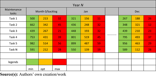
The fleet of rolling stock in Sweden shares a pool of components called high-value components (HVC). The HVCs are critical components in the vehicle such as bogies, wheelsets, braking systems etc. Each type of HVC has a time/mileage-based preventive maintenance (PM) interval for various maintenance tasks. As shown in Figure 5, the PM threshold is generally defined by a (1) minimum value – above which the component can be maintained, (2) an optimum value – above which the component must be maintained, and (3) a maximum value above which the component is not fit for operation. Based on these PM intervals, maintenance support planning is developed. This planning includes the number of maintenance tasks that is due in each month of the look-ahead time (N years) for which the maintenance plan is to be developed. An illustration of this planning is provided in Table 1
 On the left, the lowest step displays a green train icon positioned above a horizontal ledge, labeled “Minimum P M threshold value”. In the center, a slightly higher step shows a yellow train icon above a ledge labeled “Optimum P M threshold value”. On the right, the highest step displays a red train icon above a ledge labeled “Maximum P M threshold value”. The three steps rise progressively from left to right.
Critical threshold levels for PM tasks of HVC in rolling stock
On the left, the lowest step displays a green train icon positioned above a horizontal ledge, labeled “Minimum P M threshold value”. In the center, a slightly higher step shows a yellow train icon above a ledge labeled “Optimum P M threshold value”. On the right, the highest step displays a red train icon above a ledge labeled “Maximum P M threshold value”. The three steps rise progressively from left to right.Critical threshold levels for PM tasks of HVC in rolling stock
4.2.1 Dynamic parameters in the preventive maintenance policy.
The count of the expected number of planned maintenance tasks for the look-ahead time will be updated e.g. every month or when a certain number of maintenance tasks have been executed.
The number of expected maintenance tasks is dependent on the mileage of the fleet in which HVC is mounted for that particular year. Therefore, when there is a change in the mileage of any of the fleet, the count of expected maintenance tasks may change.
4.2.2 Optimal frequency of updating preventive maintenance policy
The count of expected PM tasks is updated every 15 days or monthly, based on how often the maintenance plan is to be provided to different stakeholders. The yearly mileage of the fleet is based on the operation plan for fleet performance in kilometres.
4.3 Maintenance concept
The maintenance concept for railway rolling stock includes the indenture levels and maintenance echelons of the components for which the maintenance policy is being developed. HVCs are the indenture level for which maintenance tasks are prescribed. Each task is mapped to the required resources and maintenance echelons. This mapping describes the maintenance concept. The maintenance concept is executed through preventive and corrective maintenance actions based on the maintenance policy, i.e. time/mileage-based preventive maintenance actions for HVCs.
4.3.1 Dynamic parameters
The existing indenture levels and maintenance echelons may need to adapt to evolving system requirements.
There may be changes to the existing levels of maintenance due to technology enablement or increased operational needs.
Tools and technologies for maintenance planning and execution may bring a change in scalability and modularity of the existing item hierarchy.
The maintenance echelons may be affected by changing system requirements as they may become more adaptive and rather predictive to improve the RAMS requirements on the system.
The ratio of preventive/corrective maintenance may change due to feedback from maintenance process or due to for e.g. technology enablement.
4.3.2 Optimal frequency of updating the maintenance concept
The updates in indenture-levels, maintenance echelons, and levels of maintenance should happen based on sensing the change in system requirements. This change can be sensed through the connection between the system requirements and maintenance concepts as shown in Figure 2.
4.4 Maintenance process
The maintenance process in this article is focussed on the maintenance resources planning for HVCs of railway rolling stock. A monthly maintenance resource planning for HVCs must contain the number of different maintenance tasks on HVCs for the look-ahead time, N. The formulations to achieve this maintenance support planning have been shown below. Table 2 contains the description of the notations used in the formulations.
Case 1: when the PM interval of a maintenance task for HVC is time-based.
Notations used in formulations
| Maintenance planning timeline in days | |
| The date when maintenance plan is being developed (e.g. today) | |
| The date when the last PM action was performed | |
| Lookahead time in years | |
| The number of PM actions performed over the maintenance timeline for a maintenance task of type k | |
| The PM interval of a maintenance task of type k | |
| The date for the ith occurrence of a maintenance task k over the maintenance timeline |
Source(s): Authors’ own creation/work
In this scenario, the dates of the next PM action are independent of the vehicle/fleet configuration of the HVC. The HVC is taken for maintenance after the specified time-based PM interval irrespective of being in operation or not.
To find the dates of number of PM actions of type k performed on a HVC over the look-ahead time L, first the maintenance planning timeline in days is given by:
The number of PM actions for a maintenance task performed during the maintenance planning timeline is given by:
To develop the plan monthly, the dates of expected PM actions are required. This can be calculated by:
where i = 1 to .
Now, if or occurs in the past, that is on a date before the , it is assumed for maintenance support planning purposes, to allocate all the backlog PM actions the . Therefore, the date for the ith PM action can now be given by:
By placing the for all ks, i.e. for each type of maintenance task, month wise, the requirement on the number of maintenance tasks for every month of the look ahead time can be obtained.
It should be noted, that for each record, the number of PM actions in the look ahead time should be calculated separately. Although each occurrence of a PM task k has the same PM interval, they may have a different date when the last PM action was performed on a particular HVC and vehicle configuration. Due to this, the number of PM actions during the look ahead time may vary.
In the above equations, the general term is used to denote the PM interval for a maintenance task of type k. As stated in the notations table, the interval can be substituted by , , or , based on the criteria for maintenance support planning, i.e. maximum, optimum, or minimum PM interval respectively.
Case 2: when the PM interval of a maintenance task of type k is mileage-based
To develop a time-based maintenance support plan, maintenance tasks with a mileage-based PM interval, should be converted to time-based PM interval. In this scenario, the time taken by the HVC to travel the distance in kms specified by the mileage-based PM, can be calculated based on the mileage of the vehicle in which the HVC is configured.
The railway organisations provide an estimated mileage for each of their vehicle fleets per year. This is based on monthly performance of the vehicles in the fleet as shown in Table 3. The prognosis on future mileage of the fleet is based on past performance as well as several other factors such as operation planning, state of the asset, and expected passenger or freight traffic. The monthly mileage for each year in the lookahead time can be calculated by dividing the annual mileage of the year by 12.
The monthly and average yearly performance in million kms of railway vehicle in fleet
| Vehicle | Aug-22 | Sep-22 | Oct-22 | Nov-22 | Dec-22 | Jan-23 | Feb-23 | Mar-23 | Apr-23 | May-23 | Jun-23 | Jul-23 |
|---|---|---|---|---|---|---|---|---|---|---|---|---|
| FI-VI | 2.35 | 2.37 | 2.38 | 2.40 | 2.42 | 2.42 | 2.42 | 2.44 | 2.46 | 2.48 | 2.50 | 2.52 |
| FI-V2 | 2.43 | 2.44 | 2.47 | 2.48 | 2.49 | 2.52 | 2.54 | 2.55 | 2.57 | 2.58 | 2.59 | 2.61 |
| FI-V3 | 2.48 | 2.51 | 2.52 | 2.54 | 2.56 | 2.57 | 2.59 | 2.61 | 2.64 | 2.65 | 2.66 | 2.67 |
| FI-V4 | 2.50 | 2.52 | 2.54 | 2.55 | 2.57 | 2.59 | 2.62 | 2.63 | 2.65 | 2.68 | 2.69 | 2.71 |
| FI-V5 | 2.50 | 2.51 | 2.53 | 2.54 | 2.56 | 2.59 | 2.60 | 2.62 | 2.64 | 2.66 | 2.68 | 2.70 |
| FI-V6 | 1.89 | 1.90 | 1.92 | 1.94 | 1.97 | 1.98 | 2.00 | 2.02 | 2.03 | 2.05 | 2.07 | 2.08 |
| FI-V7 | 1.87 | 1.89 | 1.91 | 1.93 | 1.94 | 1.97 | 1.97 | 2.00 | 2.01 | 2.03 | 2.04 | 2.04 |
| FI-V8 | 1.84 | 1.86 | 1.87 | 1.89 | 1.91 | 1.93 | 1.95 | 1.97 | 1.98 | 2.01 | 2.02 | 2.04 |
| FI-V9 | 1.88 | 1.88 | 1.90 | 1.92 | 1.94 | 1.97 | 1.99 | 2.00 | 2.02 | 2.05 | 2.06 | 2.08 |
| FI-VIO | 1.88 | 1.90 | 1.92 | 1.94 | 1.96 | 1.97 | 1.99 | 2.00 | 2.02 | 2.04 | 2.06 | 2.07 |
| FI-VII | 1.90 | 1.92 | 1.93 | 1.96 | 1.98 | 2.01 | 2.03 | 2.05 | 2.06 | 2.07 | 2.09 | 2.11 |
| FI-V12 | 1.79 | 1.81 | 1.82 | 1.84 | 1.85 | 1.87 | 1.87 | 1.88 | 1.90 | 1.91 | 1.92 | 1.93 |
| FI-V13 | 1.85 | 1.87 | 1.90 | 1.91 | 1.91 | 1.93 | 1.96 | 1.97 | 1.99 | 2.01 | 2.03 | 2.04 |
| FI-V14 | 0.66 | 0.68 | 0.70 | 0.72 | 0.73 | 0.75 | 0.77 | 0.79 | 0.81 | 0.83 | 0.85 | 0.87 |
| FI-V15 | 0.61 | 0.63 | 0.65 | 0.67 | 0.69 | 0.72 | 0.73 | 0.75 | 0.75 | 0.77 | 0.79 | 0.80 |
| FI-V16 | 0.71 | 0.74 | 0.75 | 0.77 | 0.79 | 0.81 | 0.83 | 0.86 | 0.87 | 0.89 | 0.91 | 0.93 |
| FI-V17 | 2.47 | 2.49 | 2.51 | 2.52 | 2.54 | 2.56 | 2.57 | 2.60 | 2.61 | 2.63 | 2.65 | 2.68 |
| FI-V18 | 2.65 | 2.68 | 2.70 | 2.72 | 2.74 | 2.76 | 2.78 | 2.80 | 2.82 | 2.84 | 2.85 | 2.86 |
| Average | 1.90 | 1.92 | 1.94 | 1.96 | 1.98 | 1.99 | 2.01 | 2.03 | 2.05 | 2.07 | 2.08 | 2.10 |
| 2024 | 2025 | 2026 | 2027 | |
|---|---|---|---|---|
| FI | 23.059 | 21.906 | 19.715 | 16.758 |
| F2 | 23.501 | 22.326 | 20.093 | 17.079 |
| F3 | 24.367 | 23.149 | 20.834 | 17.709 |
| F4 | 24.572 | 23.343 | 21.009 | 17.857 |
| F5 | 24.97 | 23.721 | 21.349 | 18.147 |
| F6 | 22.84 | 21.698 | 19.528 | 16.599 |
Source(s): Authors’ own creation/work
The algorithm to calculate the number of PM tasks in each month of the look ahead time is then given by the following steps.
Define a list of years between and
Create new columns for “monthly mileage” for each year.
Define a mapping for “fleet” values to monthly mileage values.
Extract numeric values from in kilometres and create column by multiplying the PM interval for each task to the mileage of the fleet each year.
Continue with the calculations in Case 1.
The operator requirement for maintenance support planning has been shown in Figure 6, where the planned maintenance tasks for each month of the look ahead time can be visualised. It must be noted that the planned PM actions do not always happen on time, therefore there are several pending PM actions on the maintenance planning date. These pending PM actions are referred to as backlog and put under “month 0”. The formulations to develop this plan have been discussed below:
 The horizontal axis is labeled “month 0 to 12” and displays months from month 0 through December. The vertical axis is labeled “number of pending P M tasks” and ranges from 0 to 70 in increments of 10 units. Data points labeled “task 1” through “task 20” are plotted, as indicated in the legend. Month 0 shows a tight cluster of very high values between approximately 30 and 65 tasks across all twenty categories. From January onward, the plotted points are widely dispersed but consistently lower, generally ranging between 0 and 30 tasks depending on the category. Across the year, values fluctuate slightly month to month but remain far below the initial month-zero levels, indicating that pending tasks decrease sharply after the starting point and then stabilize with modest variation across categories. Note: All numerical values are approximated.
Maintenance support planning to visualise the number of planned preventive maintenance tasks
The horizontal axis is labeled “month 0 to 12” and displays months from month 0 through December. The vertical axis is labeled “number of pending P M tasks” and ranges from 0 to 70 in increments of 10 units. Data points labeled “task 1” through “task 20” are plotted, as indicated in the legend. Month 0 shows a tight cluster of very high values between approximately 30 and 65 tasks across all twenty categories. From January onward, the plotted points are widely dispersed but consistently lower, generally ranging between 0 and 30 tasks depending on the category. Across the year, values fluctuate slightly month to month but remain far below the initial month-zero levels, indicating that pending tasks decrease sharply after the starting point and then stabilize with modest variation across categories. Note: All numerical values are approximated.Maintenance support planning to visualise the number of planned preventive maintenance tasks
The developed maintenance support planning is used to plan when the maintenance tasks should be performed. The maintenance task consists of a series of maintenance activities. The scheduling of these activities will depend on the provisioning of resources that are mapped to them.
One of the KPIs for maintenance assessment for HVC in rolling stock is the number of unwanted failures. Figure 7 shows the maintenance assessment and maintenance improvement by comparing Nf (number of unplanned failures in HVCs) to a predetermined threshold value Nt (threshold limit for number of unplanned failures in HVCs). If Nf > Nt, then a Failure mode effect and criticality analysis is conducted (FMECA). This is done, by studying the impact of the failure mode on vehicle and on overall fleet performance. If the criticality score, Cr from the FMECA is greater than Crt, then a root cause analysis of the failure is conducted.
 The flowchart begins with a box stating “Analyse the results from maintenance process”, followed by a decision diamond comparing “N f greater than N t”, where a “No” arrow leads to a box reading “Continue with existing policy” and a “Yes” arrow leads downward to a box labeled “F M E C A”; the next decision diamond compares “C r greater than C r t, where a “No” arrow again leads to “Continue with existing policy” and a “Yes” arrow leads to “Root cause analysis”, followed by a final box labeled “Recommend preventive actions”. An arrow points from this flowchart to the funnel diagram, which contains overlapping circles labeled “Equipment and system design”, “Condition monitoring or analytics or predictive technology”, and “Spare parts or maintainability or tools”, all feeding into a lower output labeled “Preventive maintenance strategy (interval based or condition-based)”.
Maintenance policy assessment and maintenance policy improvement process
The flowchart begins with a box stating “Analyse the results from maintenance process”, followed by a decision diamond comparing “N f greater than N t”, where a “No” arrow leads to a box reading “Continue with existing policy” and a “Yes” arrow leads downward to a box labeled “F M E C A”; the next decision diamond compares “C r greater than C r t, where a “No” arrow again leads to “Continue with existing policy” and a “Yes” arrow leads to “Root cause analysis”, followed by a final box labeled “Recommend preventive actions”. An arrow points from this flowchart to the funnel diagram, which contains overlapping circles labeled “Equipment and system design”, “Condition monitoring or analytics or predictive technology”, and “Spare parts or maintainability or tools”, all feeding into a lower output labeled “Preventive maintenance strategy (interval based or condition-based)”.Maintenance policy assessment and maintenance policy improvement process
The maintenance improvement consists of recommended preventive actions based on maintenance assessment. PM recommendations can be made by considering the interdependence between factors such as system design, available condition monitoring and predictive technologies, maintainability of the system and availability of resources for maintenance.
4.4.1 Dynamic parameters:
The estimated mileage of the fleet over the look ahead time
The deviation between the estimated mileage of a vehicle to that of the fleet
The deviation between annual estimated mileage and monthly estimated mileage
Unplanned failures
4.4.2 Optimal frequency of updating the maintenance process/maintenance resource planning
The yearly mileage of the fleet will be updated annually. The deviation between individual vehicle and fleet mileage should be sensed based on the performance plan and history of individual vehicles. The deviation between annual and monthly estimated mileage will be updated monthly. The prognosis on unplanned failures can be updated either based on events, i.e. updating the unplanned failure prognosis after a certain number of unplanned failures have occurred or based on a fixed time/mileage-based interval depending on the business requirements on accuracy of the developed maintenance resource plan.
4.5 Maintenance policy assessment and improvement
Maintenance policy assessment requires KPIs against which the existing maintenance policy can be assessed. These KPIs are specified by the system requirements in the first step of dynamic maintenance policy development.
The maintenance policy assessment and improvement process for HVC maintenance planning has been illustrated in Figure 7. In this study, the two KPIs that have been considered for the maintenance assessment of HVC in rolling stock are (1) Nf – number of unplanned failures at a fleet level per month, and (2) Nbacklog number of backlogs of PM tasks on the MPd. These two KPIs are assessed against pre-determined threshold values to identify the need for update in the maintenance policy. The maintenance policy assessment KPIs can be the cost incurred to maintain inventory and maintenance support for the planned PM and number of delays/safety incidents caused due to backlog PM actions.
The suggestions for maintenance policy improvement must contain objective changes in the existing maintenance policy. In the considered case study, based on the KPIs for maintenance policy assessment, changes in the existing PM policy are suggested. These changes are related to.
The revised optimisation of preventive and corrective maintenance activities.
The revised optimisation of existing PM intervals.
Reconsideration of time/mileage-based PM intervals to condition-based PM intervals.
The above improvements can be suggested, not only on the performance of the KPIs, but also based on sensing changes in the system requirements that leads to enablement of maintenance policy improvement.
4.5.1 Dynamic parameters
Unplanned failures.
Parameters leading to unplanned failures.
PM backlogs.
Parameters that affect timely maintenance leading to backlogs.
Availability and accessibility and cost of technology to enable the suggested maintenance policy improvement measures.
Change in the accuracy and precision of existing predictive models, or availability of new more efficient and effective predictive models.
4.5.2 Optimal frequency of updating the maintenance concept
The frequency of detecting unplanned failures and parameters leading to unplanned failures is event based. Firstly, it depends on the occurrence of a certain threshold number of failures. Secondly, it depends on the diagnostics of failure and the consequent identification of characteristics that impact them. A time-based monitoring of parameters such as maintenance turn-around time, and logistics time can be used to update the information on PM backlogs. The sensing of dynamic technological developments should be based on events of relevant technological advancements.
5. Conclusion and future work
A maintenance policy tailored to the initial system state may lack to optimise system availability and efficient maintenance planning for its current state. There is a need for a dynamic maintenance policy that is optimised to the current requirements and constraints of the system. The existing research on dynamic maintenance policy development has been focussed on certain dynamic characteristics within the system related to degradation or the environmental impact on degradation. In addition to dynamic degradation rates of assets, there are several other dynamic characteristics that should be considered such as internal and external system requirements, technological advancements, and development and implementation of the maintenance policy and maintenance process. However, it is a complicated task to track the dynamic parameters in the system, the environment, and the maintenance processes associated to complex technical systems due to challenges such as multi-stakeholder environment, complex system configuration, lifecycle management, resource planning and allocation etc.
A holistic, systemic, and systematic approach for maintenance policy development provides a framework for identification of these dynamic parameters. Additionally, such an approach also provides a foundation to establish the flow of information between system requirements and the maintenance process. This paper proposes an approach for dynamic maintenance policy development for railway rolling stock that is based on identification of system requirements, maintenance concepts and domain specific challenges in the maintenance support planning for railway rolling stock. The proposed approach provides a framework for constant interaction and upgrade in the maintenance policy based on changing system requirements, and changes in the maintenance process. Such an approach enables the identification of dynamic characteristics, as well as the frequencies of updates of those characteristics.
This approach can be used by stakeholders for railway rolling stock to develop a maintenance policy and plan that is aligned to the requirements of each stakeholder and is being regularly updated to reflect the backlogs and updates in the availability of resources for maintenance and maintenance support. This can be used to provide a common maintenance plan to different stakeholders enabling a common and holistic assessment of the maintenance effectiveness and efficiency of rolling stock assets. An implementation of this dynamic approach to a practical case must include sensing the relevant dynamic parameter at each stage of the approach, assessing it with change in the system requirements and adapting the existing maintenance policy accordingly.
The proposed approach for dynamic maintenance policy development has been demonstrated for maintenance support planning for railway rolling stock in this article. However, the underlying structure of the approach is generic to most complex technical systems and the maintenance process. Therefore, it can be used to develop a holistic approach for dynamic maintenance policy in other similar industrial contexts such as mining, aviation, and construction industries to identify and adapt to dynamic characteristics of the system. The future research in this direction should include the dynamic maintenance policy development with a focus on other phases of the maintenance process than maintenance support planning such as, maintenance management, preparation, improvement, assessment, and execution. Future research directions can also include the incorporation of detailed components into the proposed approach, aligning with emerging trends like predictive maintenance, and Industry 5.0.
We would like to convey our appreciation to Sweden’s Innovation Agency Vinnova, JVTC (Luleå Railway Research Center), Trafikverket, Alstom, Tågföretagen, Norrtåg, Infranord, Trasnitio, Bombardier, Sweco, Omicold, and Damill and partners for their financial support to carry out this work within the AIFR (AI Factory for Railways) project.

