


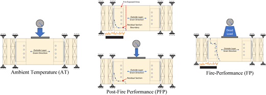
3-ply cross-laminated timber (CLT) is used to investigate the thermo-mechanical performance of intermediate-size assemblies comprised of T-shaped welded slotted-in steel doweled connections and CLT beams at ambient temperature (AT), after and during non-standard fire exposure.
The first set of experiments was performed as a benchmark to find the load-carrying capacity of the assembly and investigate the failure modes at AT. The post-fire performance (PFP) test was performed to investigate the residual strength of the assembly after 30-min exposure to a non-standard fire. The fire-performance (FP) test was conducted to investigate the thermo-mechanical behavior of the loaded assembly during non-standard fire exposure. In this case, the assembly was loaded to 67% of AT load-carrying capacity and partially exposed to a non-standard fire for 75 min.
Embedment failure and plastic deformation of the dowels in the beam were the dominant failure modes at AT. The load-carrying capacity of the assembly was reduced to 45% of the ambient capacity after 30 min of fire exposure. Plastic bending of the dowels was the principal failure mode, with row shear in the mid-layer of the CLT beam and tear-out failure of the header sides also observed. During the FP test, ductile embedment failure of the timber in contact with the dowels was the major failure mode at elevated temperature.
This paper presents for the first time the thermo-mechanical performance of CLT beam-to-girder connections at three different thermal conditions. For this purpose, the outside layers of the CLT beams were aligned horizontally.
Load-carrying capacity and failure modes of CLT beam-to-girder assembly with T-shaped steel doweled connections at ambient temperature presented.
Residual strength and failure modes of the assembly after 30-min partially exposure to the non-standard fire provided throughout the post-fire performance test.
Fire resistance of the assembly partially exposed to the non-standard fire highlighted.
Graphical Abstract
1. Introduction
In comparison to other types of construction materials, cross-laminated timber (CLT) has advantages in architectural appearance, constructability, cost and sustainability (Barber, 2018). As such, the use of CLT has been on the rise in Europe and more recently in North America (Smith and Frangi, 2014; Grasser, 2015; Pei et al., 2016). Although CLT has been employed mainly as large dimensional wall and floor panels in contemporary heavy timber structures, it is also possible to bring CLT into service as a 2D beam element (Tuhkanen et al., 2018). It has been assumed that using the CLT beam will improve the performance of the beam member against brittle splitting failure. There are different retrofitting methods such as FRP strengthening (Gilfillan et al., 2003; Dempsey and Scott, 2006; Li et al., 2014; Solarov and Glišić, 2014), utilizing steel strips (Franke et al., 2015) and self-drilling screws (Blaß and Schmid, 2001; Palma et al., 2013) to overcome this undesirable failure; however, these solutions may cause a negative influence on the performance of the member at the dowel locations during the fire (Martin and Tingley, 2000; Blaß and Schmid, 2001; Palma et al., 2013). Additionally, steel connections play a crucial role in both seismic and fire performance (FP) of contemporary timber structures, increasing the ductility and thereby improving the seismic performance of the structure against lateral forces.
In contrast, steel connections may be seriously affected by fire, losing strength and stiffness, leading to large plastic deformations and contributing to progressive collapse. In general, FP of steel connections in timber structures is influenced by parameters such as material thermal properties, temperature dependent mechanical properties and geometry of the assembly. This is a complex thermo-mechanical problem and the research conducted on the FP of the doweled steel connections is limited to the fire tests performed in accordance with the standard fire curves (Erchinger et al., 2010; Moss et al., 2010; Peng et al., 2012; Khelifa et al., 2014; Audebert et al., 2014; Palma, 2016; Hofmann et al., 2016). These standard fire curves are mostly adopted by prescriptive codes, while most of the contemporary timber structures with different amount of exposed combustible timber material have been designed through performance-based design (PBD) guidelines. The design fires determined for the PBD method include but are not limited to the standard fire curves. The heat flux of these design fires plays a significant role in charring depth, and as a result, load-carrying capacity of the structural timber elements.
Additionally, most of the standard fire curves do not capture the decay phase of the real-fire and they are more suitable for comparing the performance of different type of assemblies with each other. Furthermore, performing the standard fire test in the furnace restricts the loading condition, measurements and visual access (Gales et al., 2021). To overcome some of these restrictions, a set of experiments was designed to investigate the thermo-mechanical behavior of CLT beam-to-girder assemblies connected by T-shaped slotted-in doweled type connections before, during and after non-standard fire.
In a previous study, thermo-mechanical performance of glulam beam-to-column connections were investigated at ambient and fire conditions (Palma, 2016). Results showed reducing the gap between connecting members improved the FP of the connection. A recent study, however, showed that removing the gap between connecting members led to undesirable brittle splitting failure in the glulam members (Shabanian and Braxtan, 2022a). This study presented ambient, post-fire performance (PFP) and FP tests of glulam beam-to-girder connections with full contact (no gap) between connecting elements. Results showed that ductile dowels were critical in connection performance where brittle splitting failure in the glulam beam members was delayed or eliminated. Splitting failure in the glulam beam occurred at ambient temperature (AT), but only after large deformations in the connection; splitting failure was not observed in the PFP and FP tests on the fire exposed connection as charring during the fire degraded the wood properties and decreased the contact between connected elements. Embedment failure in the glulam beam was the controlling failure mechanism during the fire and post-fire tests.
Another study presented ambient, PFP and FP tests of glulam beam to CLT wall connections with full contact (no gap) between connecting elements to consider the effect of changing the geometry and timber lamination orientation of the header (Shabanian and Braxtan, 2022b). Results showed that the controlling failure mechanism remained to be splitting failure at AT and embedment failure in the beam during PFP and FP tests despite this change in geometry.
The current study presents a CLT beam-to-girder connection in an effort to reduce the splitting failure in the beam members. AT, PFP and FP tests were considered in this research. The CLT beam-to-girder connection is a more unique configuration and research is limited on the subject.
2. Experimental program
2.1 Assembly description
Experimental tests were conducted on symmetric, intermediate-size CLT beam-to-girder assemblies. Figure 1 illustrates the CLT beam-to-girder assembly and its geometry. Each assembly was comprised of two 3-ply CLT girders connected to a CLT beam with steel connections. Each steel connection included 4 full-length steel dowels to the joist member and 20 Type 316 stainless steel screws to each girder. Table 1 provides more detailed information on the dimensions and material type of each component.
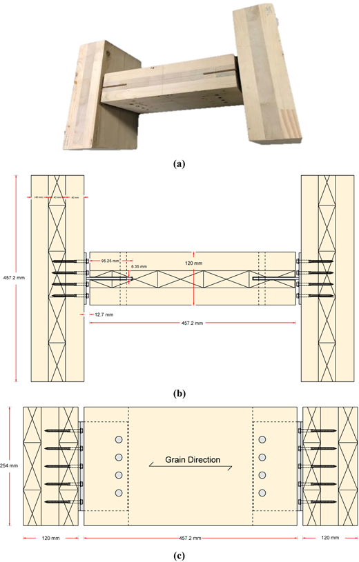
Components of the CLT beam-to-girder assembly
| Parts | Quantity | Material | Dimensions (mm) |
|---|---|---|---|
| Headers | 2 | 3-Ply CLT Girders | 254 × 120 × 457.2 mm |
| Joist | 1 | 3-Ply CLT Beam | 254 × 120 × 457.2 mm |
| Hangers | 2 | Steel Connection A572 Gr. 50 | Plate A: 114.3 × 190.5 × 4.76 mm |
| Plate B: 101.6 × 190.5 × 4.76 mm | |||
| Dowels | 2 × 4 | Steel A572 Gr. 50 | D = 12.7 mm, L = 120 mm |
| Screws | 2 × 20 | Low-carbon Steel Wire Grade 1022 | D = 6.35 mm, L = 76.2 mm |
2.2 Material description
2.2.1 Cross-laminated timber (CLT)
Both the beam and girders in the assembly studied were 457 mm long by 254 mm deep, 3-ply spruce CLT with total thickness of 120 mm. A VOC-free, formaldehyde-free, PUR adhesive was used over the entire surface of joints. The adhesive was classified as a TYPE 1 adhesive and has been approved to produce load-bearing timber components. The CLT panels had an average moisture content (MC) of 12% ( ± 2%) on delivery date and density of 5.5 kN/m3. According to the CLT manufacturer, the CLT panels had nominal char rate of 38 mm/h and flame spread index of classification B. All the samples were loaded in the gravity direction at the mid-span of the beam, in the direction perpendicular to the grain of the outside layers and parallel to the grain of the mid-layer. Table 2 shows the allowable design capacities of the CLT material used for this research.
2.2.2 Steel connection
The custom T-shaped welded steel doweled connection fabricated from gauge 7 ASTM A572 Gr 50 (ASTM A572, 2021) structural steel welded with 3.175 mm full-length fillet weld on both sides. Figure 2 displays the welded steel doweled connection and its geometry.
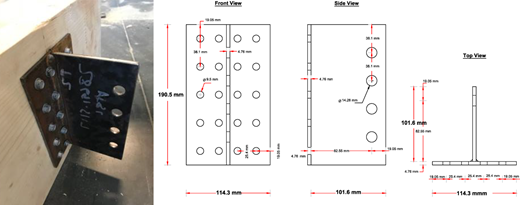
2.2.3 Steel dowels and fasteners
The full-length dowels (120 mm) are cut from 12.7 mm diameter steel rods with similar material properties as the steel connection (ASTM A572 Gr 50). The 6.35 mm diameter heavy-duty hexagonal connector screws with 76.2 mm length and 50.8 mm thread are manufactured from low-carbon steel wire grade 1022. This fastener has 1,130 MPa bending yield strength, 6.36 kN allowable tensile capacity and 3.5 kN allowable shear capacity. Plate 1 shows the steel dowels and screws placed on top of the CLT beam.
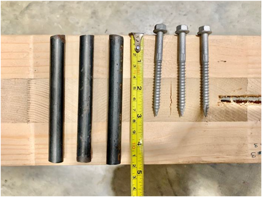
2.3 Experimental setup
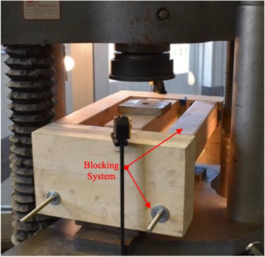
Six CLT beam-to-girder assemblies were tested in total – four at AT, one post-fire and one during fire. Plate 2, Figures 3 and 4 show the AT, PFP and FP test setup, respectively.
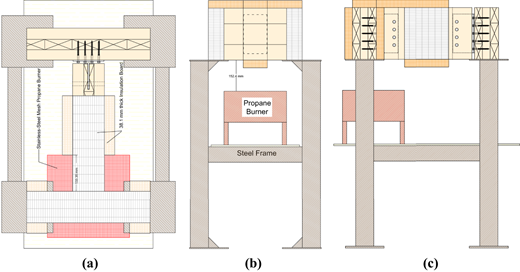
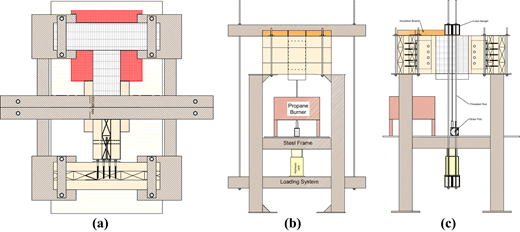
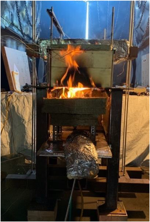
To approximate the real boundary conditions of the connections in all the fire tests, the CLT beams were exposed on 3-sides and only the top surface of the assembly was covered by insulation board. The ignition source of the non-standard fire tests was a gas burner with a nominal 305 mm by 305 open top surface, covered with stainless steel mesh. The fuel flow was manually controlled. During the FP test, the sample was fixed to the test frame with custom designed mechanical clamps.
Plate 3 shows photos of the two-step PFP test, including 30 min of non-standard fire exposure of approximately 480 °C and subsequent cooling, followed by mechanical loading to failure.
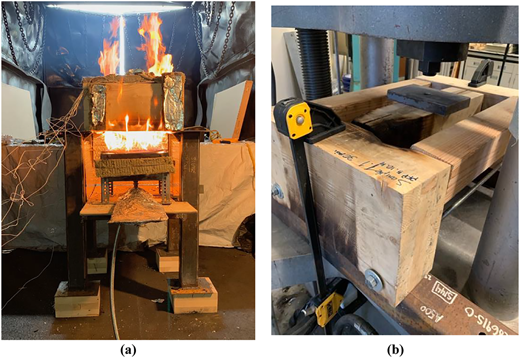
PFP30 test procedure: (a) non-standard fire test and (b) loading at ambient temperature
PFP30 test procedure: (a) non-standard fire test and (b) loading at ambient temperature
Plate 4 shows a photo of the FP test, including the application of constant mechanical load equivalent to 66% of the AT assembly capacity along with non-standard fire exposure of approximately 480 °C until failure. This higher than usual mechanical load was prescribed to accelerate the failure time of the assembly and to study the thermo-mechanical behavior of the steel connection within the assembly under a greater state of stress.
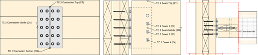
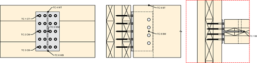
Figures 5 and 6 show the locations of the k-type thermocouples used in the fire tests. Detailed information on the test set-up is provided in related research (Shabanian, 2020).
3. Test results
3.1 Ambient temperature results
Four replicas of the CLT beam-to-girder assembly were tested at AT. The first two tests were stopped after initial failure occurred and investigated to establish the primary failure modes. Assemblies 3 and 4 were loaded until failure and the load-carrying capacity and deflection at the mid-span of the assemblies were recorded. Figure 7 shows the load-displacement of the CLT beam-to-girder assemblies tested at AT for replicas 3 and 4. The average load-carrying capacity of this assembly was 146.7 kN. The elastic region of the curve has an average slope of 10.5 kN/mm.
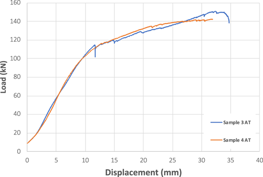
Load-displacement of the CLT beam-to-girder assembly at ambient temperature (AT)
Load-displacement of the CLT beam-to-girder assembly at ambient temperature (AT)
Plate 5 shows the failure modes that occurred during the AT test in the order observed. The failure in this assembly was triggered by the plastic embedment failure and bending of the dowels. Then row shear failure occurred in the mid-vertical layer of the CLT beam loaded in shear parallel to the grain at the dowel location (shown as sudden drops in load-displacement curves between 10 and 15 mm displacement) and finally the test was stopped after the partial splitting failure occurred at the outside layer of the CLT beam and girders. In the outside layers where the dimensional lumbers were laid out horizontally, the transferred shear load produced a tension perpendicular to the grain direction and a brittle splitting failure occurred.
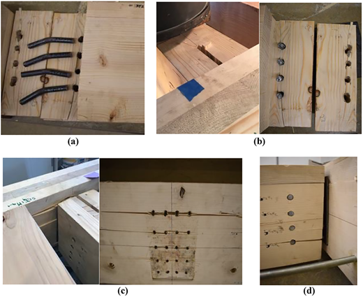
Ambient temperature failure modes sequence (a) embedment and bending of the dowels, (b) Row shear in the mid-layer, (c) splitting failure of the header side and (d) splitting failure of the beam side
Ambient temperature failure modes sequence (a) embedment and bending of the dowels, (b) Row shear in the mid-layer, (c) splitting failure of the header side and (d) splitting failure of the beam side
3.2 Post-fire performance test results
One sample was tested to study the PFP, stiffness degradation and residual load-carrying capacity of the CLT beam-to-girder assembly after heating and subsequent cooling. The results of the 30-min PFP (PFP30) test include the heat distribution during the 30 min of fire exposure and the load-displacement behavior of the burnt sample at the mid-span.
Figure 8 shows heat distribution along the sample during the 30 min fire exposure. The burner temperature rapidly increased for the first 3–4 min to approximately 480 °C and then ranged from approximately 340 °C–560 °C for the duration of the fire, with the slight fluctuations in temperature due to the manually control of the gas flow. The figure also shows the ASTM E119 standard fire curve for comparison.
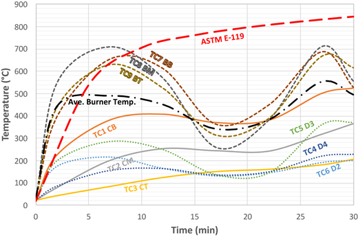
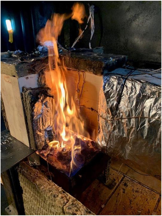
The beam temperatures at the location of TCs 7, 8 and 9 (bottom, middle and top of the beam) reached the wood ignition temperature (300 °C) and then began to increase in comparison to the burner temperature after one minute. Plate 6 shows visual confirmation of ignition over the height of the beam 1 min into the fire test.
Temperature of the three lower dowels at their tips was recorded by TCs 4, 5 and 6. The temperature of the dowel tips followed the same fluctuation pattern as the beam and burner and reached a maximum temperature of 370 °C. TCs 1, 2 and 3 recorded the temperature at the bottom, middle and top of the steel connection. After 30 min of fire exposure the maximum temperature in the bottom of the connection was 525 °C and the difference between bottom, middle and top of the connection was approximately 140 °C. According to the former studies (Lee et al., 2012; Sajid and Kiran, 2019) the post-fire mechanical properties of ASTM A572 Gr 50 remain unaffected after exposure to temperatures up to 600 °C. Therefore, no reduction in residual strength of the steel connection is expected.
In the next step, the burned sample was cleaned up and loaded at the mid-span, subject to similar boundary conditions to the AT tests. The PFP30 loading test terminated when the sample experienced major failures similar to what was observed in the AT tests and when the extension at the mid-span was around 15 mm. According to Figure 9, the load-carrying capacity of the assembly after 30 min of fire exposure was reduced to 82.5 kN, 55.8% of the AT capacity. Since the steel connection itself is expected to maintain its AT strength, this reduction in capacity is attributed to a gross loss of wood cross-section due to charring and loss of strength in the thermal penetration zone behind the char layer.
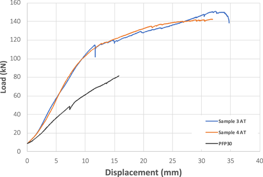
Load-displacement of CLT beam-to-girder assembly loaded after 30 min fire exposure
Load-displacement of CLT beam-to-girder assembly loaded after 30 min fire exposure
Plate 7 shows the failure modes in the PFP test replica. The embedment failure around the dowels was the dominant failure mode followed by row shear of the mid-layer of the CLT beam and plug shear of the CLT girder. In the PFP30 loading test, the steel dowels did not experience a similar level of plastic deformation and bending in comparison to the AT tests. This observation is predictable based on Figure 9 and considering that the PFP30 sample did not experience the same level of plastic deformation that AT samples went through. It is interesting to notice that the maximum plastic deformation in the dowels formed where the most degradation and charring occurred in the CLT beam. In this case, maximum charring depth in the joist member occurred at the lower end of the joist, and it was approximately 70 mm while charring depth at the dowel location section was approximately 30 mm.
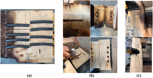
Post-fire performance failure modes sequence (a) embedment failure, (b) row shear in the mid-layer and (c) tear-out of the header sides
Post-fire performance failure modes sequence (a) embedment failure, (b) row shear in the mid-layer and (c) tear-out of the header sides
3.3 Fire-performance test results
The fire resistance (FR) of the CLT beam-to-girder assembly was studied through the coupled application of thermal and mechanical loading. A constant load equal to 98.6 kN (approximately 67% of the expected load-carrying capacity of the assembly at AT) was imposed while a non-standard fire of approximately 480 °C was applied until failure.
Figure 10 shows the heat distribution along the exposed area during the FP test. According to the recorded heat distribution, the bottom of the CLT beam ignited after 2 min. This statement is confirmed by the visual observations and recorded videos. The beam bottom temperature increased until the 9th minute and then decayed for the remainder of the fire loading. The connection temperature reached its maximum temperature of 760 °C after 40 min in the bottom (at the middle and along the edge of the weld). Between minutes 40 and 75 the temperature of the middle and top of the connection increased significantly, and the steel connection reached nearly 595 °C at the end of the test. At these temperatures, a reduction in strength and stiffness of the steel connection is expected. However, due to the reserve strength of the capacity during design, the steel connection itself does not experience failure.
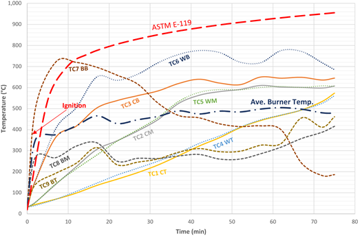
Figure 11 shows the deflection of the CLT beam at the mid-span recorded during the FP test. According to this figure, the sample failed after 55 min of non-standard fire exposure. The maximum displacement ratio occurred at this point, and it was 0.32 mm/min.
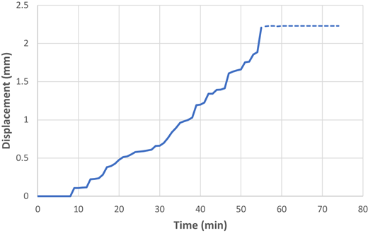
Displacement vs time at the mid-span of the CLT beam during the fire-performance test
Displacement vs time at the mid-span of the CLT beam during the fire-performance test
Plate 8 shows a series of video captures taken from recordings during the FP test. Onset of ignition at the beam bottom can be seen at 2 min. The charring development around the connection is obvious in these pictures. The CLT beam started charring from the bottom corner and the lowest dowel was exposed after 30 min to the fire. This was where the embedment failure of the CLT beam was captured for the first time. By the end of the test, the lowest dowel was only surrounded with char.
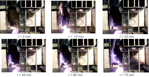
Plate 9 shows the failure modes captured during the FP test. The failure initiated by embedment failure around the lower dowels (Plate 9a) and followed by bending in the top dowel (Plate 9b).
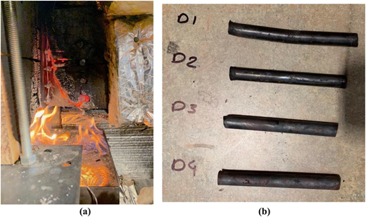
FP test images: (a) embedment failure of the beam at the lower dowel location and (b) bending of the dowel 1 (D1) at the end of FP test
FP test images: (a) embedment failure of the beam at the lower dowel location and (b) bending of the dowel 1 (D1) at the end of FP test
Returning to Figure 10, the temperature of the connection at the time of failure at 55 min was nearly 650 °C at the bottom of the connection. At 650 °C the steel is expected to maintain only 35% of its AT yield strength. Failure, however, was not observed in the steel connection itself, but instead in the timber elements. This is attributed to the extensive charring that occurred in the timber which in turn weakened the timber and led to the embedment failure in the beam.
Plate 10 shows the residual section of the CLT beam-to-girder assembly after the FP test. Extensive charring occurred around the steel connection. The maximum char depth on the header side occurred at the bottom and was equal to 40 mm. The charring progressed faster in the mid-layer of the CLT-beam in comparison with the exterior layers. In the assembly, changes in the geometry and boundary condition caused a rotation in the steel connection. However, as there was no contact between beam and girder, this rotation followed by a plastic deformation in the lower edge of the steel connection.
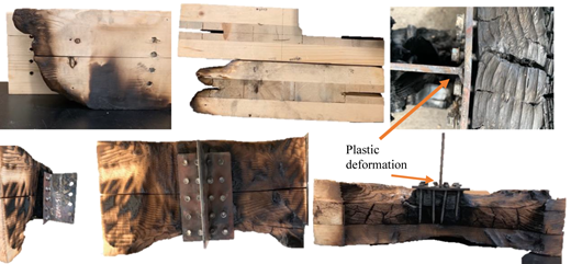
Residual section of the CLT beam-to-girder assembly after the fire-performance test
Residual section of the CLT beam-to-girder assembly after the fire-performance test
4. Discussion and conclusions
This experimental study demonstrated the performance of a CLT beam-to-girder assembly connected with T-shaped connections subject to vertical load before, during and after non-standard fire.
For the assemblies tested at AT, ductile embedment failure of the CLT-beam around the dowels and plastic bending of dowels were the dominant failure modes. This is significant inasmuch that brittle, splitting failure of the beam was not the controlling failure mechanism as is often seen in similar connections with timber elements loaded perpendicular to the grain. The samples also experienced secondary failures due to row shear failure in the mid-layer of the CLT-beam and splitting failure between the screws and finally at the outside layers of the CLT-beam.
For the assembly loaded after 30 min non-standard fire exposure (PFP test) embedment failure, bending of the dowels, row shear failure of the beam, and plug shear of the headers occurred, but importantly, no splitting occurred in the CLT members. The load-carrying capacity of the assembly was reduced by 44% compared to the ambient capacity. The maximum recorded temperature of the steel connection during the PFP test was 525 °C. Therefore, the reduction in load-carrying capacity of the assembly is attributed to the gross loss of wood cross-section due to charring and loss of strength in the thermal penetration zone behind the char layer.
For the loaded assembly tested during the non-standard fire (FP test), ductile embedment failure and bending of the top dowel were the only failure modes observed when the specimen failed after 55 min of coupled fire and mechanical loading, with an imposed load of 67% of ambient capacity. In this case, the steel connection deformed slightly in the lower edge.
All the deformed dowels in this research experienced second mode of failure (Johansen, 1949) and only one plastic hinge formed in the middle of the dowels. Increasing the side member thickness (joist width) with a larger embedment length and using longer dowels could increase the ductility and load-bearing capacity of the connection for this research. This could also improve the FP of the connection.
In both the PFP and FP tests, extensive charring in the assemblies caused a degradation of timber strength and gross loss of section. The presence of the steel connection promoted the charring process and facilitated the failure of the wooden beam at the connection area.

