Contribution by W. M. Jenkins
I was surprised that the work in Sebastian (2009) was done without the use of the computer. Computationally the problem can be placed in the field of structural reanalysis, since this is what is required each time a design feature is changed. I put one of the examples through my own general plane frame reanalysis software (Jenkins, 2001, 2002, 2003a, 2003b) in which a network (not actually a neural network but in the style of one) is used iteratively to update the analysis each time a design change is made. When the system is running and the analysis option is called, the network continues from the present state and iterates to a new equilibrium solution, the current analysis forming the starting point for the revision. An appropriate data base of sections, springs and plate properties needs to be provided for the designer. All design variables can be changed during the process. Starting from the initial design cross-section in Section 5.2, my design reached a satisfactory state after three design changes, introducing reinforcing plates of 20 and 25 mm thickness.
The advantages of this approach are
(a) speed of computation
(b) ease of communicating design changes to the software
(c) all results can be displayed including displacements – incidentally these can be critical in the example quoted
(d) intermediate designs can be retained in memory for subsequent recall
(e) formulae not required
(f) the spans are represented by varying segment lengths, which can be controlled by changing the node positions
(g) the segment representation can be refined by introducing more nodes thus increasing the number of segments.
The fundamental development of engineering formulae remains crucially important and students would be well advised to read this paper before using any software.
Authors' reply
Advances in computers have been exploited in studies by the contributor and others (e.g. Apostol and Santos (1996); Cherkaev and Cherkaev (2008); Friedmax and Fuchs (1987); Kanagasundaram and Karihaloo (1983)), leading to iterative computational tools that efficiently gravitate towards design solutions for complex structures.
For application of a UDL to a hyperstatic span comprising two stiffness zones, scrutiny of results from parametric structural analyses by computer may lead to awareness of a coincidence between the point of stiffness change and the point of contraflexure, both along the span when moment extrema occur, but that awareness remains merely an observation for the specific examples considered. By contrast, the algebraic derivations given in Sebastian (2009) constitute formal proofs of the extrema criterion. Further, as regards the use of reanalysis software, the statement ‘formulae not required' is at odds with the myriad stiffness formulae that underpin computer structural analysis.
Turning now to Section 5.2 of Sebastian (2009) where, in Figure 9(b), λ = 8 should be γ = 8. In that section, extra plating in the negative moment zone was considered for various rotational spring stiffnesses at the inner support. An alternative, for any given spring stiffness, is to use different thickness plates in the negative and positive moment zones. Any assumed plate in the positive moment zone creates a known section capacity there and so – given the applied load – leads to a known required negative moment capacity over the inner support. The minimum plated section needed to carry this negative moment is one consideration. The stiffness profile along the span – and so the minimum extra plate thickness in the negative moment zone – needed to cause at least that negative moment to develop is a separate consideration.
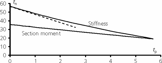
These issues were investigated by programming relevant expressions – including Equation 10 and a suitably rearranged form of Equation 8 from Sebastian (2009) – into a spreadsheet. Figure 11, where tn and tp refer to plate thickness in the negative and positive moment zones respectively, shows results for γ = 8. It is immediately apparent that, for 0 ≤ tp≤ 5·7, the stiffness profile requirement governs. Note how tn varies rapidly and nonlinearly with tp, particularly at small tp (dashed tangent line) – increasing tp from 0 to only 5·7 mm causes tn to drop dramatically from 57 mm to 19 mm – and so a designer must exercise caution in this regime. It is such global perspectives on the problem, rather than isolated plate solutions, that are of interest here. Of course the practicalities of connecting thin plates (bonding may be preferable to welding), plate buckling (to which bonding may provide more resistance), deflections, shear in the webs, transfer stresses in the medium (welds, adhesive) connecting the plates to the original beam (stated in Sebastian (2009)) and so on should all be checked for the plated beams.
Since the publication of Sebastian (2009), the author has pursued further algebraic analyses of continuous end spans with the added complexities of differential settlement between supports and of travelling point loads along the spans. The results, published in Sebastian (2010), reveal that moment extrema again occur when the points of contraflexure and of stiffness change coincide. Another key discovery presented in Sebastian (2010) is that there is a unique point of stiffness change along the span for which the moments are insensitive to the stiffness ratio along the span. This latter discovery is counter-intuitive, as the received wisdom is that alteration of stiffness distribution along a hyperstatic span leads to change of the moment distribution along the span under a given load form. In addition to its scientific significance, this discovery may be usefully applied in design as discussed in Sebastian (2010).
The papers (Sebastian, 2009, 2010) and the present discussion are useful to students, designers and researchers who appreciate interaction with computational routines and who also seek penetrative insights into the influence of stiffness profiles on moments in loaded hyperstatic spans.