This paper aims to investigate and compares the performance of mould inserts with conformal cooling channels (CCC), fabricated via additive manufacturing (AM), and conventional cooling systems, both made from aluminium alloys. The comparative analysis encompasses simulation results, critical manufacturing considerations and part quality, focusing on warpage and crystallinity.
A test part was designed to assess warpage and crystallinity using conventional and conformal cooling systems. Six CCC configurations were simulated, with one selected due to its improved performance. Injection moulding simulations enabled to compare the performance between conventional and conformal cooling systems. Structural simulation analysis of the AM mould with CCC ensured mechanical suitability and mass reduction through topology optimization and lattice structures integration. Mould inserts were manufactured, and parts were fabricated with amorphous and semicrystalline materials to compare warpage and crystallinity.
AM moulding inserts with CCC and topology optimization achieved over 50% material reduction, a 15% decrease in mass and 36% waste savings. CCC lowered mould insert temperatures by 4.8% on average, reducing crystallinity by 4.1 ± 2.89% due to improved cooling rates.
Most studies on CCC focus on steel-based moulding inserts. This research investigates aluminium alloys for conventional and conformal cooling systems, leveraging their superior thermal conductivity. The study combines simulation analysis with an evaluation of injected plastic part quality for semicrystalline and amorphous polymers. Future work encompasses exploring variations of the selected CCC design.
1. Introduction
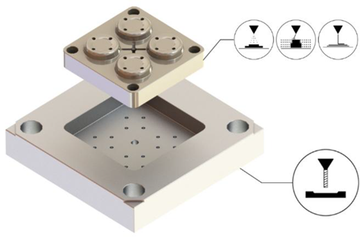
In response to market demands, the mould industry has integrated new technologies to accelerate product development, leading to the emergence of hybrid moulds (Figure 1). This concept involves combining traditional mould manufacturing techniques with additive manufacturing (AM), resulting in reduced production costs and shorter lead times for injection moulding components. Numerous studies have explored variations and advancements in these tools, highlighting their ability to produce parts with superior properties compared to those manufactured using conventional methods (Dimla et al., 2005; Saifullah and Masood, 2007; Au and Yu, 2007; Wang et al., 2011).
However, the economic implications of incorporating additive manufacturing (AM) into injection moulding inserts remain unclear and are highly case-dependent. Some studies suggest that subtractive manufacturing is more advantageous for producing moulding inserts intended for larger, less complex parts (Booysen et al., 2010; Ilyas et al., 2010). On the other side, despite the still relatively high cost of AM technologies, costs reductions of 75% and time savings up to 78% can be achieved using injection moulding inserts manufactured by these means (Combrinck et al., 2012; Boccardi et al., 2019; Kuo and Lin, 2012; Tosello et al., 2019). The main reason is the incorporation of conformal cooling channels (CCC), which can feature various cross-sections and significantly reduce cooling and cycle times. This innovation enhances productivity, lowers energy consumption, and results in higher-quality parts (Ilyas et al., 2010; Ahn et al., 2010; Park and Dang, 2017; Shinde and Ashtankar, 2017; Vojnová, 2016; Saifullah et al., 2016).
Some authors have studied design variations for CCC. Previous research indicates that using non-circular cross-sections, such as square channels, can improve cooling efficiency (Shayfull et al., 2002). Additionally, studies have analysed the effectiveness of cooling channels with variable spacing for mould tooling applications (Au and Yu, 2014). Moreover, the inclusion of lattice structures produced via AM may not only induce a turbulent regime in the cooling fluid but also reduce the mould’s mass while maintaining comparable thermomechanical performance. This approach can lead to energy cost reductions of up to 13% and mass savings of up to 30% compared to injection moulding inserts without lattice structures (Koresawa et al., 2016; Wu et al., 2016).
When comparing injection moulding inserts with CCC to conventional moulds made from highly thermally conductive materials, such as copper, the cycle times were similar; however, the inserts with CCC exhibited lower residual stresses (Luboš and Jozef, 2013). In other cases, moulding inserts made from low thermal conductivity materials, such as titanium alloys, and incorporating CCC demonstrated performance comparable to conventional steel injection moulding inserts, further validating the efficiency of CCC (Borg and Rochman, 2013). Although many studies have analysed CCC, steel is predominantly considered as building material for the moulding inserts (Arman and Lazoglu, 2023; Kanbur et al., 2020; Kanbur et al., 2022). CCC represent a promising solution for improving cooling efficiency, however, defining an optimal configuration remains challenging, particularly for parts with complex details, thin-walled features and deep grooves. Consequently, research has also explored the use of highly thermally conductive materials, such as nickel, aluminium, and copper, as alternatives to conventional steel moulds (Arman and Lazoglu, 2023). Despite the higher thermal conductivity of aluminium alloys compared to steel, studies focusing on their application in injection moulds remain limited. Aluminium has primarily been employed for simpler applications such as, blow moulding (Liew et al., 2018) and extrusion dies (Reggiani and Todaro, 2019; Özsoy, 2021) and, as a filler in epoxy-based injection moulds to enhance thermal conductivity (Altaf et al., 2013; Arman and Lazoglu, 2023). More recently, as a building material in powder bed fusion processes for mould fabrication (Kanbur et al., 2022). However, aluminium alloys exhibit lower rigidity, mechanical strength and durability than steel, requiring careful consideration of their mechanical limitations when leveraging their thermal advantages (Arman and Lazoglu, 2023). While CCC facilitate uniform cooling, reducing warpage and cycle time (Arman and Lazoglu, 2023; Kanbur et al., 2020), the use of highly conductive materials enables efficient heat transfer across broader mould surfaces. Integrating CCC into moulds manufactured from materials such as aluminium alloys remains an underexplored strategy, yet it holds potential for further enhancing cooling performance and improved productivity (Arman and Lazoglu, 2023).
Additionally, while significant work has been done on the numerical evaluation of CCC designs, fewer studies assess the quality of the plastic parts produced using moulds with conformal cooling (Dimla et al., 2005; Saifullah et al., 2007; Au and Yu, 2007; Wang et al., 2011).
This study aims to analyse various designs of CCC for application in injection moulding inserts used to produce plastic parts. The CCC designs were evaluated through computational fluid dynamics (CFD) simulations using ANSYS Fluent, and the shrinkage of plastic parts for each design was predicted using Moldex3D simulations. Given the lower structural strength of aluminium alloys compared to steel, the injection moulding insert with the optimal CCC design underwent a mechanical performance evaluation using ANSYS Static Structural, considering the stresses from injection moulding cycles.
2. Materials and methods
As injection materials, two different materials were considered: an amorphous General-Purpose Polystyrene, GPPS 165H from INEOS Styrolution Group GmbH and a semicrystalline homopolymer Polypropylene, PP 579S supplied by SABIC®. Matrices with different degree of crystallinity and molecular weight were chosen because, under controlled cooling conditions, it is possible to evaluate the volume of crystallites and hence the degree of crystallinity.
The materials considered for the mould inserts include an aluminium alloy AW-6082 from Universal Afir - Aços e Ligas Especiais S.A. for the conventional manufacturing of mould inserts with straight-drilled cooling channels, and another aluminium alloy CL31AL (AlSi10Mg) supplied by Concept Laser GmbH for mould inserts with CCC. The properties of the materials used were set according to previous characterization studies (Silva et al., 2022) and are shown in Table 1.
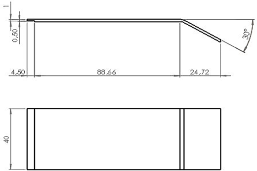
The test part (Figure 2) was designed to monitor thermal behaviour when processed by the different moulding inserts. With a nominal angle of 30°, it is also well-suited for assessing one of the main defects caused by non-uniform cooling, namely, warpage.
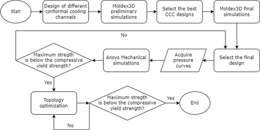
The procedure for selecting the optimal injection moulding inserts (Figure 3) begins with the design of various CCC configurations. These designs are initially tested through Moldex3D preliminary simulations to identify those with the most potential for application in injection moulding inserts. Next, full injection moulding process simulations are conducted for the selected cooling systems, maintaining consistent cooling times. For the final CCC configuration, pressure curves are generated and used in mechanical simulations via ANSYS Static Structural to ensure that the maximum stress remains below the compressive yield strength of the material. If this condition is met, the moulding inserts intended for AM can undergo topology optimization to reduce mass, minimize material usage, and improve production speed, without compromising structural performance. A final verification ensures that the results from the topology optimization meet the required mechanical performance standards.
3. Moulding inserts development
3.1 Conformal cooling system design
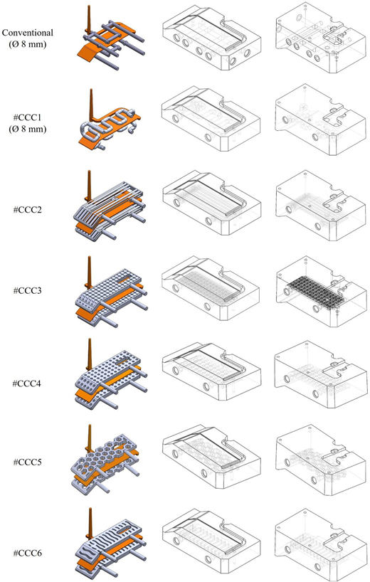
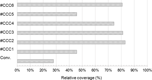
The cooling system geometries defined and analysed are summarized in Figure 4, where the grey volumes indicate water-filled regions.
The conventional cooling channel consists of straight-drilled channels with a diameter of 8 mm, positioned at a distance ranging from 18 mm to 31 mm from the part (Figure 4, Conventional). For all conformal cooling channel (CCC) designs, this distance is consistently maintained at 18 mm. Geometry #CCC1 represents the most common CCC configuration, featuring a channel diameter of 8 mm. Alternative CCC geometries were developed based on a “bain-marie” concept, wherein nearly the entire geometry of the part is surrounded by water (Figure 5) (Booysen et al., 2010). Specifically: Geometry #CCC2 incorporates a distributor and collector channel design; Geometry #CCC3 is based on a lattice structure configuration that was used for heat sink applications with the purpose of enhancing cooling efficiency (Silva, 2024); Geometry #CCC4 includes turbulence-inducing pins in the shape of cylinders placed equidistantly over the available space to ensure uniform coolant flow throughout the channel (Ilyas et al., 2010); Geometry #CCC5 is inspired by honeycomb structures for improved heat dissipation; Geometry #CCC6 employs wavy blades to optimize coolant flow dynamics by forcing it to do a specific predetermined trajectory.
The thermal performance of the various cooling systems designs was evaluated using Moldex3D software. Initially, a mesh study was conducted on the conventional moulding inserts, resulting in the selection of 2-mm mesh elements for the filling and packing analysis. The viscosity behaviour of the injection moulding materials was modelled using Modified Cross Models. Key process parameters were chosen based on the recommendations provided by the material suppliers (Table 2).
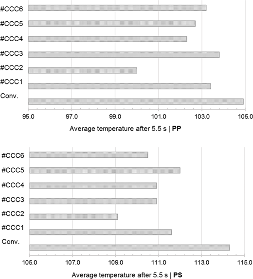
To comprehensively evaluate the performance of the different cooling channel designs, the average packing temperature was recorded (Figure 6) at a specific time point (5.5 s after the packing phase) ensuring that the part temperature was below the ejection temperature, allowing a meaningful comparison between designs. The results indicated that, for both amorphous (GPPS) and semicrystalline (PP) polymers, the average temperature after the packing phase was up to 4.7% lower for #CCC2. In addition to providing a faster cooling rate, CCC2 also demonstrated more uniform cooling and improved part quality, which contributed to its selection as the optimal design. Consequently, the mechanical strength of the moulding inserts with these cooling channels was analysed using ANSYS software and considering a Static Structural analysis.
3.2 Mechanical simulations
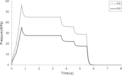
Based on the results of the injection moulding process simulations, the filling pressure curves generated in Moldex3D (Figure 7) were imported into ANSYS software to assess the structural performance of the AlSi10Mg moulding inserts considering a Static Structural simulation analysis.
The loads were applied over the cavity and core surface of the mould inserts while the constraints were defined over the lateral surfaces, perpendicular to the cavity and core surface. All degrees of freedom were constrained not allowing translational or rotational motion. Stress and displacement contours were generated to evaluate their distribution across the mould inserts. The mechanical simulations aimed not only to validate the structural performance of the non-conventional moulding inserts but also to apply principles of topology optimization. This involved reducing material in areas with the lowest stress levels while staying within the available volume constraints. To achieve this, arrays of auxetic unit cells were incorporated around the injection moulding inserts. These cells featured a periodic rib/strut length of 2 mm, a diameter of 0.6 mm, and an angle of 30°, as shown in Figure 8.
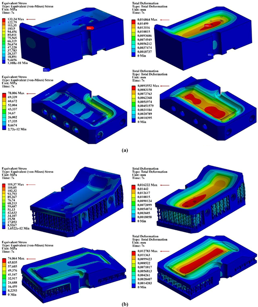
Figure 9 (a-b) presents the simulation results, highlighting the maximum values of Von Mises stress and total deformation for the core and cavity of the analysed moulds. A summary of the main results is provided in Table 3. The results showed a similar or even better mechanical performance for these lighter moulding inserts. Weight and volume were reduced at least 15%, with lower von-Mises stresses. Core displacement was the same while in the cavity increased only three thousandths of a millimetre.
Since the compressive stress in both moulding inserts was less than half of the values reported in the experimental characterizations (Silva et al., 2022), the mass and volume optimizations were considered effective for subsequent steps.
3.3 Injection moulding process simulations
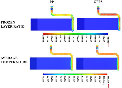
To complete the analysis of the developed injection moulding inserts (both conventional and non-conventional), simulation analysis of the entire injection moulding cycles was conducted using the same parameters presented in Table 2. The cooling time for conventional cooling channels was adjusted to ensure that the frozen layer ratio exceeded 50% and that the average temperature throughout the part’s thickness and feed system remained below the freezing temperature. Specifically, the freezing temperature was set at 110°C for PP and 104°C for PS (Figure 10). This adjustment resulted in cooling times of 17 s for PP and 20 s for GPPS.
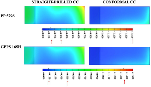
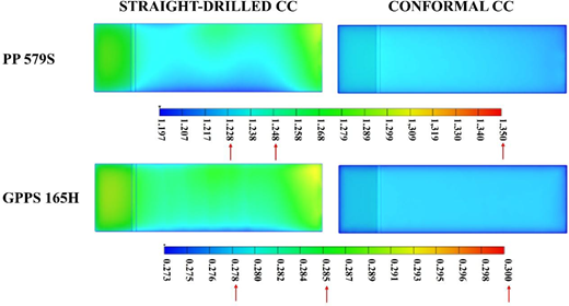
Figure 11 presents the numerical simulation results for the part temperature differences using injection moulding inserts with straight-drilled cooling channels and CCC. The main temperature values, including the maximum and the most frequently observed temperatures for each material and type of cooling channel, are indicated with arrows. In straight-drilled cooling channels, sharp turns at the intersections between adjacent channels hinder coolant flow, causing a sudden pressure drop. This reduces the downstream cooling capacity and further enhances uneven cooling (Saifullah and Masood, 2007). By contrast, with the same cooling time, CCC provides significantly lower and more uniform surface temperatures across the part.
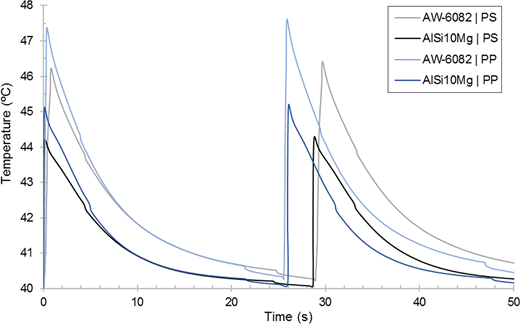
The impact of conformal cooling channels is also evident in the evolution of the cavity surface’s average temperature over two injection cycles (Figure 12). When using AlSi10Mg with CCC, the average temperature of the moulding inserts can be reduced by approximately 3% for amorphous polymers and 2% for semicrystalline polymers. This indicates that the reduction is more pronounced for materials with higher crystallinity.
Thermal and pressure gradient are the most important parameters influencing material shrinkage and warpage (Kurt et al., 2009). Figure 13 shows the volumetric shrinkage result, highlighting both the maximum value and the values corresponding to the most frequently occurring colour ranges, for both materials and types of cooling channels. As expected, the results show that shrinkage is higher for the semicrystalline polymer (PP). The influence of the cooling channel type reveals that, in both cases, shrinkage not only decreases when the mould insert incorporates CCC but also becomes more uniformly distributed, resulting in reduced warpage.
3.4 Production of the moulding inserts
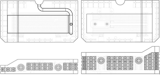
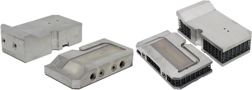
The conventional moulding inserts (Figure 14, left) were manufactured using AW-6082 aluminium alloy through subtractive manufacturing on a DMU 50 universal CNC milling machine from DMG Mori. In contrast, the optimized moulding inserts with CCC (Figure 14, right) were produced using the aluminium alloy AlSi10Mg and AM via powder bed fusion (PBF) on an M2 Cusing machine from Concept Laser GmbH. The AM process utilized a layer thickness of 50 µm and an upright orientation to minimize build height for time efficiency and to reduce the need for support structures. The remaining parameters were a laser power of 370 W with a spot size of 60 µm, scanning speed and hatch spacing of 1400 mm/s and 90 µm, in an atmosphere inert with nitrogen to prevent oxidation and reactivity, with a maximum oxygen content of 0.2%. To avoid the influence of residual thermal stress, the building platform is heated at 200°C during the entire production. To facilitate post-processing with CNC milling machine, all external surfaces were intentionally oversized by 0.5 mm to 1 mm. This allowed for subsequent machining of as-built surfaces and manual threading of holes for water inlets, outlets and sensor installations.
The total production time, including pre-production and post-production operations, as well as material consumption for both manufacturing approaches, is summarized in Table 4.
Analysing the data in Table 4, it is important to highlight that while the production time is longer for moulding inserts manufactured via AM, the operator involvement is limited to less than 16 h, covering pre- and post-production operations. In contrast, subtractive manufacturing requires operator involvement for nearly the entire production time. The production time for AM mould inserts is long, partly due to the integration of complex structures. Although lattice structures reduce material usage, the sintering process is time-consuming because of intricate scanning paths and extended laser exposure times (Colombini et al., 2024; Tancogne-Dejean et al., 2016; Yan et al., 2012). Regarding economic feasibility, the conventional manufacturing of the analysed mould inserts is less expensive in terms of both material and production. However, when comparing a hybrid mould integrating conformal cooling solutions, lattice structures for mass reduction, and a highly conductive aluminium alloy with a fully conventional mould made from a different aluminium alloy, it is important to consider the productivity advantages of the hybrid design. These advantages include the ability to produce high-quality plastic parts at a faster rate, lower energy consumption, greater design flexibility for complex shapes (e.g. conformal cooling channels and lattice structures) and easier mould handling due to the reduced weight. Furthermore, the use of AM for moulding inserts resulted in a material reduction of over 50% and a final mass decrease of approximately 15%, significantly minimizing material wastage.
4. Injection moulding
For the experimental trials, an Engel 200V/45 injection machine was used, equipped with a Ø30 screw diameter and a clamping force of 450 kN. The initial injection moulding parameters for both moulding inserts and injection materials were based on Moldex3D simulations (Table 2). Only adjustments had to be made to the cushion to get completely full and compliant parts. The cooling time was fixed for both cooling configurations to isolate the effects on part quality being 17 s for PP parts and 20 s for GPPS parts. The cooling fluid was water.
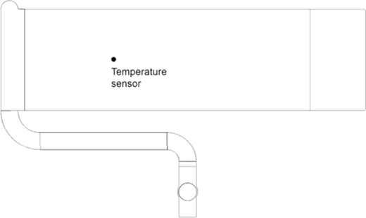
After process stabilization, 10 shots were produced for each material and moulding insert, and temperature values were recorded using a Type-K thermocouple and data acquisition systems. The sensor location is shown in Figure 15. Experimental temperature measurements revealed variations in the average temperature of the moulding inserts, summarized in Table 5. The use of additively manufactured moulding inserts resulted in a more noticeable reduction in average temperature, especially for the semi-crystalline polymer, as predicted by the simulations. In summary, with CCC, the average temperature of the moulding inserts decreased by up to 4.8%.
5. Part analysis
5.1 Warpage
The first criterion used to compare the conformally cooled mould with the conventionally cooled mould was the degree of part warpage. The tab angle of five injection-moulded specimens was measured using the Vision Measurement System ZEISS COMET®6 3D Scanner, with a resolution of 117 µm. The measurements taken on the core side are presented in Table 6 and indicate improvements in the plastic parts’ angle. As expected, these improvements were more pronounced in parts produced with the semi-crystalline polymer, while they were almost negligible in parts produced with the amorphous polymer. Predicted warpage is always below average warpage, reaching deviations of around 3% for semi crystalline mouldings and 1% for amorphous mouldings.
5.2 Relative crystallinity
Differential scanning calorimetry (DSC) analysis was conducted using a Netzsch DSC 200 F3 Maia. For each injection moulding insert, three polypropylene (PP) samples, each weighing 10 mg, were analysed over a temperature range of 30°C to 200°C at a heating rate of 10°C/min. The enthalpy of fusion for each sample was calculated using Netzsch Proteus software. The cooling rate was found to have a significantly stronger influence on the crystallinity of polymers. Relative crystallinity was determined based on the heat required to melt the semicrystalline polymer. The heat associated with fusion was reported as percent crystallinity by normalizing the observed heat of fusion to that of a 100% crystalline sample of the same polymer. According to TA Instruments (Blaine, 2002), the heat of fusion for 100% crystalline PP is 207 J/g. The results, summarized in Table 7, indicate a decrease in crystallinity when AM moulding inserts were used. The higher cooling rate associated with AM inserts reduces the melt crystallization temperature and the amount of polymer that crystallizes from the molten state (Saifullah and Masood, 2007).
6. Conclusions and future work
This study involved the development of moulding inserts with advanced temperature control systems. Among six designs of CCC, the design based on the distributor concept demonstrated the most promising results. To accommodate the pressures encountered during the injection moulding process for both materials (a semicrystalline homopolymer polypropylene [PP] and an amorphous general-purpose polystyrene [GPPS]), the chosen cooling channel design underwent mechanical validation following topology optimization for mass reduction. Two types of moulding inserts were manufactured: one with straight-drilled cooling channels produced via conventional machining in AW-6082 aluminium, and the other with conformal cooling channels fabricated using additive manufacturing (AM) in AlSi10Mg aluminium alloy. The AM process achieved material waste savings of approximately 36%, even after considering the subsequent machining required for finishing the inserts. Under identical injection moulding parameters, as predicted by Moldex3D simulations, mouldings produced with both moulds exhibit no significant differences in warpage and only minimal, yet perceptible, differences in crystallinity. Additionally, these parts displayed lower crystallinity due to the enhanced cooling efficiency provided by the AM-designed conformal cooling channels. Future work will focus on exploring new configurations and variations of the analysed CCC designs to further optimize cooling performance. Additionally, investigating advanced manufacturing approaches for hybrid moulds could be beneficial, particularly by integrating AM with conventional machining. For instance, initiating AM over a pre-machined mould plate could reduce production time, material usage, and overall costs. Another key aspect for future study is the durability of aluminium moulds when used with different polymer materials, including reinforced polymers, for higher-volume production and also considering parts with thin and delicate features. Understanding the wear and mechanical performance of aluminium moulds under extended operational conditions will help define their applicability and advantages compared to conventional steel moulds. Finally, further research into post-processing techniques (e.g. thin film deposition, application of coatings) can improve mould cavity quality, enhance structural integrity, and reduce wear, ultimately increasing the lifespan and efficiency of hybrid moulds with CCC.