The purpose of this study is to reduce wheel–rail vibration noise (with the noise level increasing by approximately 9 dB for every doubling of train speed) by enhancing wheel damping. Besides, it verifies the performance of the damping wheel and provides support for the engineering application of low-noise wheels.
This study takes the damping ring-constraint layer composite wheel as the research object. First, it proposes a wheel scheme combining a damping ring and constrained damping. Then, it verifies the natural frequency and damping of the proposed wheel via 3D finite element modeling and modal analysis. Finally, in the laboratory, the wheel–rail relationship test setup is used to conduct tests on two types of wheel structures (nondamping wheel and damping wheel) under radial and axial excitation.
The damping wheel significantly reduces the corresponding radiated sound power level, with an overall noise reduction of approximately 10 dB or more, especially in the high-frequency region (around 3,150 Hz). The damping ring reduces high-frequency noise, while the constraint layer suppresses medium-low frequency noise. The combined structure outperforms single-component structures in the full frequency range, as it can suppress both high-frequency whistling noise and medium-low rolling noise.
The originality of this study lies in proposing a wheel scheme that combines a damping ring and constrained damping. The study’s value is to provide a theoretical basis and technical guidance for the engineering application of low-noise wheels in rail vehicles.
1. Introduction
With the acceleration of urbanization and the increasing demand for transportation, urban rail transit, as an efficient and environmentally friendly mode of transportation, has made significant progress globally. With its rapid development, the problem of train noise has become increasingly prominent. It not only affects the environmental quality along the line, but also reduces the riding comfort of passengers. The noise generated by train operation can be divided into external noise and internal noise. External noise mainly includes aerodynamic noise, wheel–rail noise, and traction noise. Wheel–rail vibration noise is one of the main sources of noise in rail transit. Previous studies indicate that when the train speed is doubled, the increase in wheel–rail noise can reach approximately 9 dB (Lotz, 1977). Under high-speed conditions, wheels with thin-walled structures such as rims and spokes are the key parts where noise radiation occurs (Sheng, Jones, & Thompson, 2005). In addition, the vibrations generated during train operation can also propagate to nearby buildings through the ground, which can cause noticeable vibrations (4–80 Hz), as well as secondary structural noise indoors in nearby buildings (He, Zhang, Yao, He, & Sheng, 2023).
The noise inside urban rail transit vehicles is mainly caused by wheel–rail radiation noise transmitted through the air and structure. Low-frequency noise is mainly transmitted through the structure, while high-frequency noise is mainly transmitted through the air (Wang, Jiao, & Chen, 2019; Zhou, Feng, Yin, Luo, & Liu, 2023).
Generally speaking, the vibration of the wheels is transmitted upward through the structural components of the vehicle, forming a vibration transmission path from the axle box through the frame to the vehicle body (Jones & Thompson, 2000). In this transmission process, vibration energy is transmitted through the structure of the vehicle to the interior of the vehicle, especially the floor and other structural parts, which in turn generate secondary structural noise inside the carriage. When running in a small radius section, friction occurs between the wheel rim and the steel rail, causing more severe vibration. The secondary radiation of whistling becomes the dominant noise inside the car, seriously affecting the physical and mental health of passengers. (Zhou et al., 2023).
At present, the main methods for reducing railway noise include sound insulation walls along the line, track bed renovation and vibration and noise reduction of wheel bodies, etc (Song, 2023).Wheel damping technology, with its advantages of low cost and simple construction, has become an important development direction. Scholars have conducted extensive research on damping wheels: on the one hand, a visco-elastic damping layer is added to the surface of the wheel spoke plate to increase structural damping (Wang et al., 2019); on the other hand, damping rings are embedded on the inner side of the rim or the outer side of the wheel plate, and vibration is suppressed by energy dissipation through the friction interface. Many studies show that thickening the damping layer and the constraint layer can significantly enhance the vibration reduction effect (Cui, Zhou, Lu, & Wang, 2021). By adopting a combined design (such as a damping ring and a visco-elastic layer), it can simultaneously act on the mid-low frequency and high frequency bands, effectively reducing vibration noise across the entire frequency range.
However, systematic research on the application of damping rings and constraint layers to wheels is still rare. Therefore, this article proposes a design scheme of a structure with damping rings and constrained damping. Vibration reduction mechanism is analyzed, and its performance is verified through finite element simulation and experiments. It can provide a reference for the design and application of low-noise wheels for rail vehicles (Li et al., 2025).
2. Research background
The spokes of rail train wheels have a large area and a small wall thickness, making them the main area where vibration energy is concentrated.
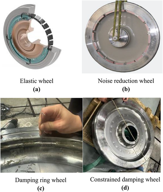
In the wheel–rail coupling system, the noise radiated by wheel vibration accounts for a large share of the wheel–rail noise. Especially in the wheel–rail whistling sound and rolling noise during high-speed driving, the high-frequency components originate from the intense vibration of the wheels. Recent researches show that adding damping materials to the wheel structure can effectively suppress vibration and noise. Common structural forms of damping wheels (Brunel, Dufrénoy, & Demilly, 2004) include: elastic wheels, noise reduction wheels, damping ring wheels and constrained damping wheels, as shown in Figure 1.
At present, damping wheels mainly include elastic wheels, resonant noise reduction block wheels, damping ring wheels and constrained damping wheels. Therefore, it is of great significance to develop a combined structure wheel with both frictional damping and visco-elastic shear damping. On the one hand, the damping ring provides mechanical contact energy dissipation and can significantly attenuate high-frequency vibrations (Mao, Yang, & Xu, 2021). On the other hand, the constraint layer increases the structural damping ratio, which can suppress low and medium-frequency resonance (Mao, Yang, Zhang, & Xu, 2019).
The utilization of the two damping mechanisms will effectively reduce the full-frequency vibration response and radiated noise of the wheels. Based on this background, this article studies and designs a combined wheel structure of damping ring and constrained damping, and conducts theoretical and experimental verification. The results can provide a reference for the low-noise wheel technology of rail transit.
3. Design and mechanism analysis
3.1 Structural design of damping wheels
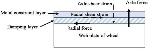
In this design scheme, the wheel is composed of a standard steel base layer, a damping layer and a constraint layer, and a damping ring is equipped at the rim position. The base layer is a traditional straight-spoke steel wheel shown in Figure 2, providing structural strength and support. The damping layer is arranged on the inner side of the wheel spoke plate or rim of the vehicle. It is made of elastic materials such as high-damping rubber and fixed to the surface of the base layer through bonding or clamping. During the vehicle vibration process, it undergoes deformation, converting mechanical vibration energy into internal heat energy. Its modulus and loss factor directly affect the vibration damping performance. Appropriately increasing the thickness of the damping layer or the loss factor can significantly enhance energy dissipation. The constraint layer is covered outside the damping layer, and high modulus steel plates are selected to form a typical visco-elastic sandwich structure with the damping layer (Ding, 2025).
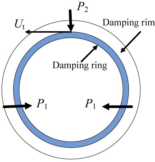
This structure restricts the deformation space of the damping layer, strengthens its shear strain field, enables the visco-elastic material to dissipate vibration energy more fully, and is connected to the base layer through reliable bonding or mechanical fasteners. The damping ring is an independent annular component installed in the center groove of the rim. It usually adopts a composite structure of metal-rubber-metal, with a concentric circular cross-section. The opening is closed and fixed by an elastic connecting piece (Xiong & Lei, 2006). It generates damping through dry friction at the interface when the wheel vibrates, and has a particularly significant inhibitory effect on high-frequency axial vibration. The damping ring and the constrained damping layer work in coordination to reduce the wheel vibration response and noise radiation over a wide frequency range.
3.2 Vibration reduction mechanism of damping wheel
The composite ring design enables the damping ring to possess the dual characteristics of friction damping and visco-elastic shear damping, which can meet the vibration control requirements in the medium and high frequency bands (Brunel, Dufrénoy, Charley, & Demilly, 2010).
The analysis of the damping mechanism shows that this combined structure integrates two energy dissipation mechanisms. Firstly, the damping ring directly dissipates the vibration energy through interfacial friction, which is particularly significant in suppressing high-frequency excitation and can weaken the corresponding modal responses under both radial and axial vibrations. Secondly, the constraint visco-elastic layer significantly increases the damping ratio of the low and medium frequency modes through shear deformation, and reduces the amplitude of the resonant peak by changing the natural frequency distribution of the structure and increasing the loss factor. The research results also show that appropriately increasing the thickness of the damping layer and the constraint layer is conducive to further enhancing the energy dissipation capacity (Chen et al., 2024).
In summary, the damping ring and the constrained damping layer not only expand the vibration damping frequency band, but also take into account the energy dissipation paths of multiple vibration modes, thereby achieving efficient and wideband vibration and noise control. Vibration reduction analysis of damping rings is shown in Figure 3.
4. Modal simulation analysis
4.1 Establishment of wheel model
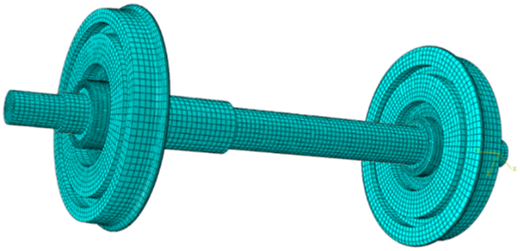
The test wheel is a straight spoke wheel with an outer diameter of 840 mm, a tread width of 135 mm, a spoke thickness of 36 mm and a shaft hole diameter of 205 mm. The wheel material is steel, with a density of 7,800 kg/m3, a modulus of 2.1e11 Pa and a Poisson's ratio of 0.3. A finite element model of the wheel is established, as shown in Figure 4, and the wheel is meshed with 30,524 elements.
4.2 Modal analysis and results
The model includes a standard steel wheel body, a visco-elastic damping layer attached to the web (and its steel restraint layer), and a composite damping ring on the inner side of the rim. The material properties adopt the linear elastic model of steel and the frequency-dependent loss factor parameter of visco-elastic materials. The model mesh adopts tetrahedral solid elements, especially densified at the interface between the damping layer and the constraint layer, to accurately capture shear deformation. The damping ring structure is also meshed to simulate the contact relationship between its elastic connectors and the wheel.
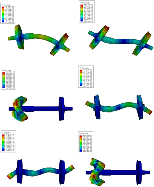
Free mode analysis is conducted in the range of 0–5,000 Hz to obtain the main vibration modes and natural frequencies of the wheel set. The simulation indicates that the 0-pitch circle (axial direction of the rim), 1-pitch circle (axial direction of the spoke plate) and radial modes are the mode groups that contribute the most to wheel–rail noise. After introducing the loss factor of visco-elastic materials into the modal dissipation model, the increase in the damping ratio under the influence of damping measures is calculated. Analyzing the impact on the system response, the results can be obtained. Modal vibration mode diagram of wheel set is shown in Figure 5.
The natural frequency and mode shape of the model are calculated by using the free modal analysis method, and the measured modal damping ratio is introduced into the simulation to reflect the damping energy dissipation effect (Qiu, 2022). The simulation results show that the first few modes of the wheel are the vertical bending mode, the radial bending mode and the torsional mode in sequence, which are consistent with the theoretical expectations (Gao, Xu, Pang, Li, & Wang, 2024). The calculated natural frequency is in good agreement with the experimentally measured value, with an error of less than 5%.
It can be seen from this that the established finite element model can accurately reflect the vibration characteristics of the damping combined wheel. Further comparative analysis reveals that, compared with the standard wheel, the addition of the damping layer and the constraint layer causes a slight change in the natural frequency of the structure and significantly increases the damping ratio of each mode. In the subsequent simulation, the modal superposition method is applied to estimate the vibration response and acoustic radiation of the wheel after adding damping measures, in order to guide the experimental design and result verification.
5. Experiment analysis
To evaluate the vibration and noise reduction performance of the combined damping wheel, a variety of test conditions and measurement schemes were designed. Frequency response tests and acoustic tests were conducted under static suspension conditions to obtain the frequency response function and sound power level of the wheels, respectively. The above tests were repeated under different excitation directions and load conditions to verify the vibration and noise reduction effects of the damping structure under various working conditions (radial excitation, axial excitation, etc.). In addition, the comparative test also included the testing of standard undamped wheels under the same conditions to obtain reference data.
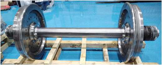
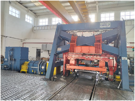
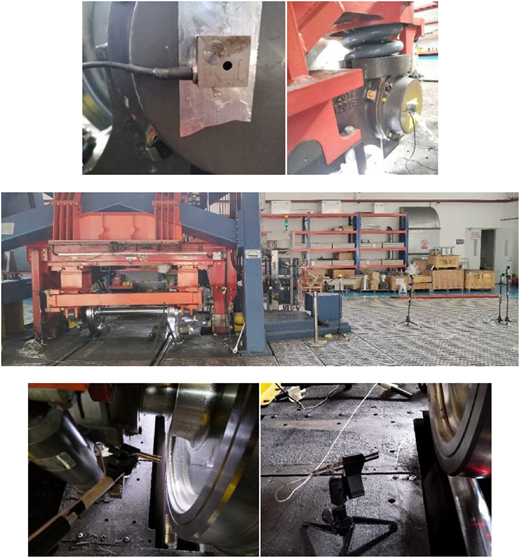
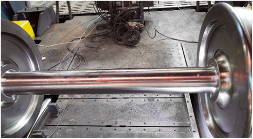
Using a 1:1 high-speed wheel–rail relationship test bench to conduct vibration and noise tests on low-noise wheelsets with different structures, analyze the vibration and noise test data and compare the noise reduction effect of low-noise wheels. The schematic diagram of the tested wheel set is shown in Figure 6 and the test wheelset is shown in Figure 7.
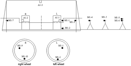
In this test, the measurement points were arranged to install acceleration sensors along the wheel structure at the tread, rim and web, etc., to collect vibration acceleration signals in different directions. For the sound radiation test, the sound pressure level was measured in a semi-anechoic chamber by using ball impact excitation (steel balls fall radially and hit the rim), and 20 microphones (in compliance with ISO3745 standard) were arranged in an array on the spherical surface around the wheels. All sensors recorded signals in real time through a data acquisition system, and usually high-speed ADCs and signal processing software were used to obtain frequency domain and time domain data. The layout diagram of the measurement points for this test is shown in the following Figure 8. The schematic diagram of the layout of measuring points in this experiment is shown in the following Figure 9.
Through the above experiments, parameters such as the acceleration spectrum, transfer function and overall sound power level at each measurement point of the wheel were obtained, providing a basis for the subsequent comparative analysis of the effects of different damping structures. All signals were analyzed by FFT spectrum to calculate the vibration transmission gain and sound level variation, and then the vibration reduction and noise reduction efficiency were evaluated.
6. Analysis of experimental results
6.1 Analysis of undamped wheel test results
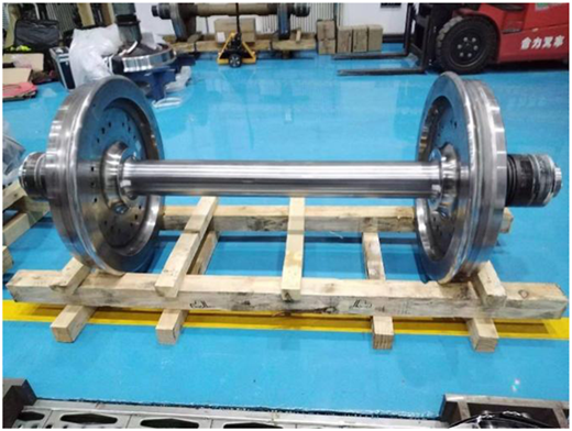
The undamped structural wheelset is shown in Figure 10, without damping rings or other damping structures. Vibration and noise tests are conducted on the wheelset under different working conditions, and the test results are shown in the following text.
6.1.1 Vehicle speed range of 50 km/h-R300 m working condition
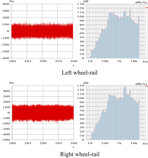
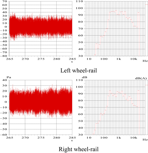
The time-domain and frequency-domain analysis results of different noise measurement points at different positions under the operating conditions of 50 km/h-R300 m are shown in Figure 11.
The equivalent continuous A-weighted sound pressure level results calculated under the operating conditions of a vehicle speed of 50 km/h-R300 m are summarized in Table 1.
6.1.2 Vehicle speed range of 100 km/h-R500 m working condition
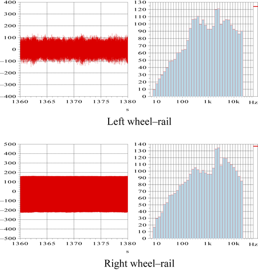
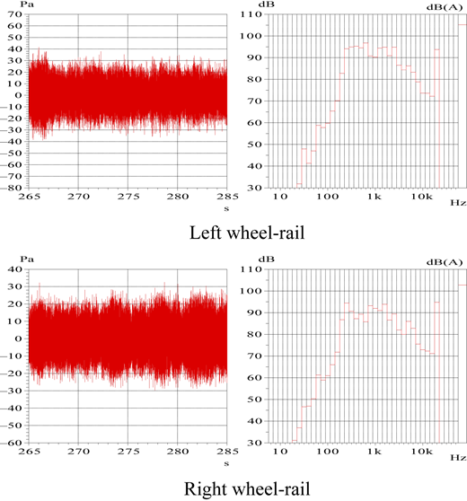
The time-domain and frequency-domain analysis results of different noise measurement points at different positions under the operating conditions of 100 km/h-R500 m are shown in Figure 12.
The equivalent continuous A-weighted sound pressure level results calculated under the operating conditions of a vehicle speed of 100 km/h-R500 m are summarized in Table 2.
6.1.3 Comparison of results under different working conditions
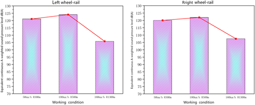
Through the wheel–rail test device, experiments under other working conditions were conducted using the same method. The working conditions included 100 km/h-R500 m and 160 km/h-R1300 m. The experimental results under different working conditions were compared and analyzed. The equivalent continuous A-weighted sound pressure level noise test results obtained at different positions under different working conditions are shown in Figure 13.
From the above figure, it can be seen that the A-level of wheel–rail noise decays as the distance from the sound point to the center of the wheel axle increases. As the wheel speed increases, the noise level also increases. Meanwhile, as the radius of the curve decreases, the noise level also significantly increases.
6.2 Analysis of damping wheel test results
The wheelset with a damping ring and overall constrained damping structure, as shown in Figure 14, was subjected to vibration and noise tests under different working conditions. The test results are shown in the following text.
6.2.1 Vehicle speed range of 50 km/h-R300 m working condition
The time-domain and frequency-domain analysis results of different noise measurement points at different positions under the operating conditions of 50 km/h-R300 m are shown in Figure 15.
The results of the equivalent continuous A-weighted sound pressure level and effective acceleration values calculated under the operating conditions of a vehicle speed of 50 km/h-R300 m are summarized in Table 3. The acceleration direction shown in the table has been adjusted to the standard coordinate system direction of the rail vehicle.
6.2.2 Vehicle speed range of 100 km/h-R500 m working condition
The time-domain and frequency-domain analysis results of different noise measurement points at different positions under the operating conditions of 100 km/h-R500 m are shown in Figure 16.
The equivalent continuous A-weighted sound pressure level results calculated under the operating conditions of a vehicle speed of 100 km/h-R500 m are summarized in Table 4.
6.2.3 Comparison of results under different working conditions
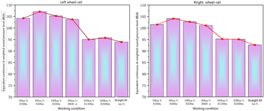
Through the wheel–rail test device, experiments under other working conditions were conducted using the same method. The working conditions included 80 km/h-R400 m, 100 km/h-R500 m, 60 km/h-R800 m, 160 km/h-R1300 m, 200 km/h-R2000 m and a straight line 80 km/h. The experimental results under different working conditions were compared and analyzed. The equivalent continuous A-weighted sound pressure level noise test results obtained at different positions under different operating conditions are shown in Figure 17.
From the above figure, it can be seen that under the condition of a curve radius of R300 m at a speed of 50 km/h, the noise level at the wheel–rail position is 104.2 dB (A); at a speed of 100 km/h with a curve radius of R500 m, the noise level at the wheel–rail position is 105.2 dB (A); The A-level of wheel rail noise gradually decays with the increase of the distance from the sound point to the center of the wheel axle. As the wheel speed increases, the noise level also increases; as the radius of the curve decreases, the noise value significantly increases.
6.3 Comparative analysis of damping structures
The sound pressure level results of non-brake disc wheelsets subjected to different damping and vibration reduction measures are analyzed, and the analysis results are as follows.
6.3.1 Vehicle speed range of 50 km/h-R300 m working condition
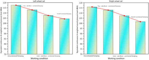
The equivalent continuous A-weighted sound pressure level noise test results of different damping structure wheelsets at different positions under the working conditions of 50 km/h-R300 m are compared, as shown in Figure 18.
From the above figure, it can be seen that under the working conditions of 50 km/h-R300 m, the wheel–rail noise value at the left wheel–rail without constrained damping is 117.5 dB (A), and after increasing the overall constrained damping, the noise value is 104.2 dB (A), a decrease of 13.3 dB (A). The noise values measured at other locations also have the same pattern.
6.3.2 Vehicle speed range of 100 km/h-R500 m working condition
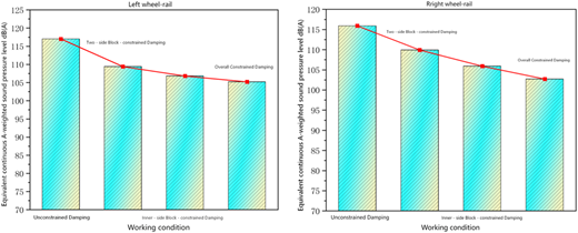
The equivalent continuous A-weighted sound pressure level noise test results of different damping structure wheelsets at different positions under the working conditions of 100 km/h-R500 m are compared, as shown in Figure 19.
As shown in the results, the test results are consistent with the simulation results. The damping structure significantly improves the vibration and noise characteristics of the wheel. Compared with standard wheels, damping rings and constrained damping layers play complementary roles in different frequency bands: damping rings effectively suppress high-frequency modes (>1,000 Hz), while constrained damping layers mainly reduce mid and low-frequency responses (200–1,000 Hz). The combination of the two can achieve a wider frequency band of vibration attenuation within the range of 200–5,000 Hz.
The damping ratio of the combined structure in multiple key modes is significantly improved, and the amplitude of vibration transmission is significantly reduced.
Noise tests show that under most working conditions, the overall sound power level reduction is larger than 10 dB, with the maximum reduction in the high-frequency band being approximately 13.3 dB(A), and there is also significant suppression in the low-frequency band.
In conclusion, the experiment verifies the synergistic effect of the damping ring and the constrained damping combined structure, which can significantly reduce the wheel vibration response and noise radiation in multiple frequency bands.
7. Conclusion
The simulation and test results show that the damping ring and the constrained damping layer play complementary roles in different frequency bands. The damping ring mainly suppresses the high-frequency modes (>1,000 Hz), while the constrained damping layer effectively reduces the mid and low-frequency responses (200–1,000 Hz). The combined structure exhibits significant vibration attenuation effects within the range from 200 Hz to 5,000 Hz. The damping ratio increases significantly in multiple key modes, and the vibration transmission amplitude is notably reduced.
The acoustic test results show that under most working conditions, the overall acoustic power level reduction of the combined damping wheel is ≥ 10 dB, and the maximum reduction in the high-frequency band (about 3,150 Hz) can reach 13.3 dB (A), and there is also significant suppression in the low-frequency band. This indicates that the combined structure can not only suppress high-frequency howling but also reduce the rolling noise of medium and low frequencies.
The test compares the wheel performance of a single damping ring, a single constrained damping layer and the combination of the two. The results show that the single damping ring wheel mainly reduces high-frequency noise, the single constraint layer wheel mainly suppresses medium and low-frequency noise, while the combined structure outperforms the single structure in all frequency bands and has a more stable noise reduction effect.
The engineering significance of this structure lies in providing a feasible low-noise wheel solution, which helps to meet the noise standards of urban rail transit and improve operational comfort. In the future, further research will be conducted on the dynamic performance in the actual operating environment, as well as the optimization strategies for working in coordination with noise reduction measures on the track side (such as track TMD), in order to comprehensively enhance the noise reduction capability of the vehicle-ground system.