


A user-friendly HTML-based open-source software has been developed for structural shielding design of medical X-ray imaging facilities. Based on values published by the NCRP Report N° 147 the software allows thickness calculations for different materials used in conventional X-ray rooms, mammography rooms and computed tomography rooms, diminishing errors resulting from the use of curves. The software focuses on the optimization principle by considering workload distributions instead of applying all the workload at a single high operating potential. The input data can be those recommended by the NCRP Report N° 147 or, if the facility has its own data, they can be used instead. With the implemented methodology, the code validation was performed by comparison of the results with a study case provided by the Report. The software application is available in two languages (English and Spanish) and provides the accuracy of the method presented, as well as assisting the physicist in shielding computations in a user-friendly manner. This software tool is available upon request to the corresponding author.
1. Introduction
In Argentina there are not any specific national standards about shielding design. However, in order to fulfil radiological protection requirements, the Spanish CSN 5.11 standard [1] and the NCRP Report N° 147 [2] are followed. The latter contains some new approaches and additional information compared to the Spanish guide. Previous research has shown the main differences between these reports: the NCRP Report N° 147 applies the workload distribution as a function of the peak kilovoltage (kVp) instead of performing the calculations assuming the work is carried out at the maximum kVp [3]. Unlike CSN 5.11 standard, allowance has been made for the shielding contribution made by attenuation by the image receptor assembly. This can be a major help in calculation of the amount of shielding under an imaging table, for example.
Although at first glance it might seem to be an easy and trivial job, shielding design for medical X-ray imaging facilities may be a difficult task since several variables and data must be taken into account, which means the calculation of barrier requirements include many uncertainties. It has been thoroughly and worldwide pointed out in the literature [4–6]. The design and shielding barriers in a diagnostic X-ray department generally follows the ALARA principle. It means that, in practice, the exposure levels are kept “as low as reasonably achievable”, taking into consideration economical and technical factors [7].
While practical shielding of diagnostic X-radiation is most often achieved with gross increments of sheets of lead, it can be replaced with a precise and accurate technique, with few assumptions and which allows a variety of more cost-effective materials to be considered for protective barriers.
The strategic planning concept involves the use of shielding options dictated by a knowledge of the radiation sources in a facility, the expected primary X-ray beam direction (use factor), the occupancy and usage of adjacent rooms (occupancy factor, controlled and uncontrolled areas), the type of radiation to be considered (primary, scattered or leakage radiation), construction characteristics of the facility existing walls (primary or secondary barriers, floors and ceilings), people to be protected (workers or members of the public) [2,8].
Different computer codes have been developed for the calculation of shielding [9]. However, currently use of applications tends to be mainly from portable devices such as cell phones, tablets and laptops [10]. Therefore, the design and development of software feasible of being installed in different electronic devices is very interesting, even more if they allow for the estimation and review of shielding thicknesses for medical X-ray rooms. This app was developed with the aim of applying an algorithm based on current regulations (NCRP Report N° 147), both in Spanish and English languages. Even though English is widely used in technical and scientific fields, the Spanish version makes this software truly useful and helpful in a very large geographical region such as Latin America and other countries where this language is vastly spoken. The calculation of shielding is simplified for each facility incorporated in the app avoiding errors resulting from the use of curves. While there is no substitute for experience in shielding design, almost anyone using this app should find it easy to understand and implement, since it includes worked‐out examples and a user’s help guide.
2. Materials and methods
This work focuses on shielding design for radiographic, mammography and computed tomography (CT) installations. The design is performed by applying a formalism based on the radiation energy distribution, which was obtained experimentally and takes into account both the buildup factor and the energy spectrum of X-ray beams. The NCRP Report N° 147 recommendations were followed, meaning, workload distribution, use and occupancy factors, attenuation factors, dose-length product (DLP), among others, were applied as suggested by this standard [1].
2.1 Shielding design criteria
Shielding design or verification criteria were established based on air kerma limits. These values depend on whether it is a controlled area or not. Following the NCRP Report N° 147 recommendations, a 5 mSv annual effective dose restriction for workers, which means a maximum air kerma rate of 0.1 mGy per week in controlled areas must be applied. Since the annual effective dose limit is 1 mSv for members of the public, a default 0.02 mGy per week value for air kerma in uncontrolled areas was used. However, users can modify this value when using the software, which gives the app more versatility to be used where the dose limits change depending on the installation or the country under consideration.
Regarding use and occupancy factors, default values are those suggested by the literature. Nevertheless, as mentioned in the previous paragraph, users can enter their own values when running the application. Also, for calculation purposes, all variables defined in the literature were used [3].
For the calculations of primary barriers, traditionally it is assumed that the primary beam hits the barriers without being previously attenuated. This is a fairly conservative assumption, since the intensity of the primary beam is significantly reduced by the attenuation produced by the patient and the image receptor. In the software the user can choose how to do the calculation considering the attenuation produced by the image receptor [11].
Shielding thickness results are obtained for five different materials: lead, standard concrete, gypsum, glass and solid wood. For each material the characteristic parameters of attenuation (α, β, γ) depend on whether the radiation is primary or secondary. In all cases these parameters are obtained from the NCRP Report N° 147 and cannot be entered by the user.
2.2 Calculation methodology
The procedure for calculating the thickness of primary barriers is described by the following equations:
Air kerma of the primary beam per unit of workload (mGy/mA.min) at one-meter distance from the X-ray emitting source. It is the so-called performance of the RX tube at each kVp.
Workload depending on the operating potential.
Air kerma one meter of the power RX per patient, for distribution of workload () unshielded.
: Average number of patients examined per week.
: Use factor.
Distance from the RX source to the primary barrier.
Total air kerma at the distance corrected by the use factor ().
: Maximum transmission allowed to the shielding so as not to exceed the maximum value of the kerma in air allowed (), corrected by the occupancy factor ().
: Air kerma limit, according to the type of adjacent area.
: Occupancy factor.
Thickness of the shielding material calculated for the primary barrier.
α, β, γ : Characteristic parameters of the attenuation of the material used as shielding.
The procedure for calculating the thicknesses of secondary barriers is described by the following equations:
: Air kerma due to leakage radiation one meter away from the RX source.
: Air kerma due to scattered radiation within one meter of the scattering source, with a determined scattering angle.
: Distance from the point of emission of the X-rays to the point of calculation.
: Distance from the point of dispersion to the point of calculation.
: Maximum transmission allowed to the shielding so as not to exceed the maximum value of the air kerma allowed (), corrected by the occupancy factor ().
2.3 Software architecture
HTML language was chosen because it allows publishing information globally. Calculations were carried out by applying JavaScript tools. The portability to different electronic devices is guaranteed by the Bootstrap framework applied.
HTML is the standard markup language for creating web pages and web applications. HTML can embed programs written in a scripting language such as JavaScript, which affects the behavior and content of web pages. JavaScript is a high-level, interpreted programming language characterized as dynamic, weakly typed, prototype-based and multi-paradigm. It enables interactive web pages and thus is an essential part of web applications. Bootstrap is a free and open-source front-end framework for developing websites and web applications. It contains HTML and CSS-based design templates for typography, forms, buttons, navigation and other interface components, as well as optional JavaScript extensions. It concerns itself with front-end development only.
3. Results
Figure 1 shows a flow diagram describing the app design. References:
- I.
Functions that make visible fields to be fulfilled in the forms (basic and advanced fields), according to the barrier (primary or secondary) selected. It is applied to conventional X-ray and dedicated chest rooms.
- II.
Function that makes visible fields to be fulfilled in both forms (basic and advanced fields) in order to estimate secondary barriers for mammography rooms.
- III.
Function that makes visible fields to be fulfilled in both forms (basic and advanced fields) in order to estimate secondary barriers for CT rooms. The form dedicated to advanced fields allows entering DLP values applied in different procedures instead of using those suggested by the NCRP Report N° 147.
- IV.
After the room and the barrier are selected, the user must decide if the form will be fulfilled for basic or advanced fields, taking account of the available information. Each form already has specific fields uploaded depending on the type of room and barrier under consideration. When estimating the primary barrier thickness, the attenuation or pre-shielding produced by the image receptor is considered.
- V.
Shielding thickness results are shown in a table for five different materials (lead, standard concrete, gypsum, glass and solid wood).
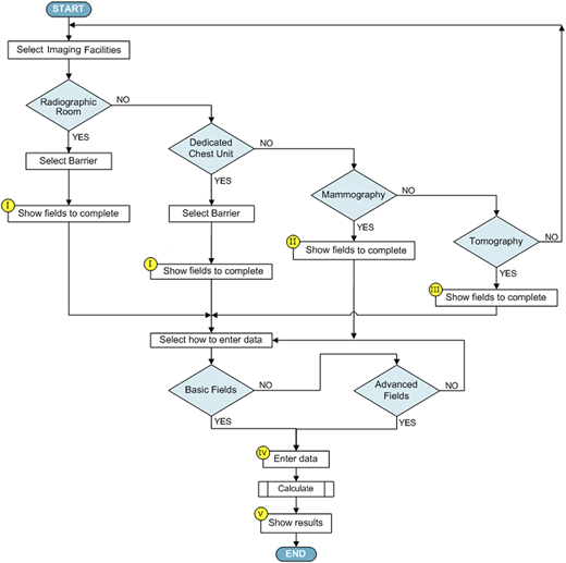
Figure 2 shows the main screen of the application, where the user must select the type of room, and whether the type of barrier corresponds. Only one option can be selected for both cases, however once the thicknesses have been calculated, the user can return to this tab, select another room or another barrier in the same room and perform the calculations for it.
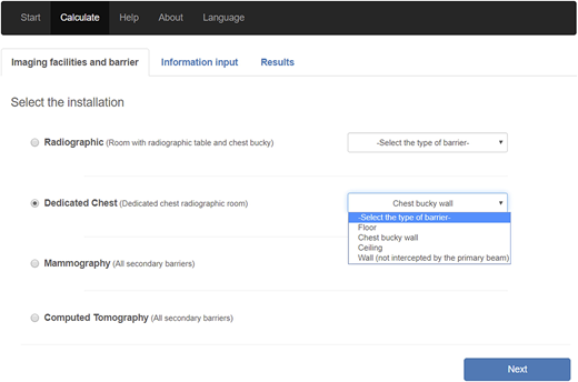
Main screen of the application, where the facility and type of barrier should be selected.
Main screen of the application, where the facility and type of barrier should be selected.
Calculations for primary barriers can be performed by:
fulfilling basic fields and taking account of default values provided by the NCRP Report N° 147 (Figure 3). Or,
fulfilling advanced fields, which allows entering the facility own information and data. In this case, because the app assumes the workload is performed at the kilovoltage entered by the user, the results are more conservative than in the other option (Figure 4).
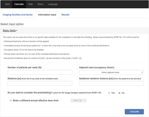
Screenshot of the input information tab, basic fields form, conventional X-ray or dedicated chest room.
Screenshot of the input information tab, basic fields form, conventional X-ray or dedicated chest room.
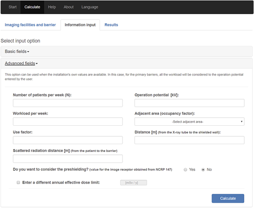
Screenshot of the input information tab, advanced fields form, conventional X-ray or dedicated chest room.
Screenshot of the input information tab, advanced fields form, conventional X-ray or dedicated chest room.
Due to the complexity of obtaining some parameters to calculate the secondary barriers, these are calculated by applying input data from the NCRP Report N° 147 [9].
The results will be added in the table below those calculated previously. Figure 5 shows the screenshot of the Results tab.
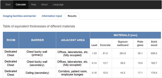
Screenshot of the results tab. The results table shows the selected facility and barrier and the thicknesses (in millimeters) of the barriers for five types of materials (lead, standard concrete, plaster, glass and solid wood).
Screenshot of the results tab. The results table shows the selected facility and barrier and the thicknesses (in millimeters) of the barriers for five types of materials (lead, standard concrete, plaster, glass and solid wood).
Figure 6 shows how the application interface adapts when used on mobile devices. In this screenshot it can be observed that, with respect to the interface for larger resolutions, the fields are kept reorganizing their distribution and size, this is the characteristic that the Bootstrap framework provides.
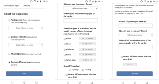
Screenshot on cell phone for the Selection Facility tab (left), Input Information tab in Basic fields for Tomography (center), Input Information tab for mammography (right).
Screenshot on cell phone for the Selection Facility tab (left), Input Information tab in Basic fields for Tomography (center), Input Information tab for mammography (right).
To validate the computer code, it was used a modeling problem provided by NCRP Report N° 147. The exercise determined thickness values for radiographic room shown in Figure 7. Based on the design presented, the Table 1 shows a comparison between the results obtained with the computational code and the results of NCRP Report N° 147.
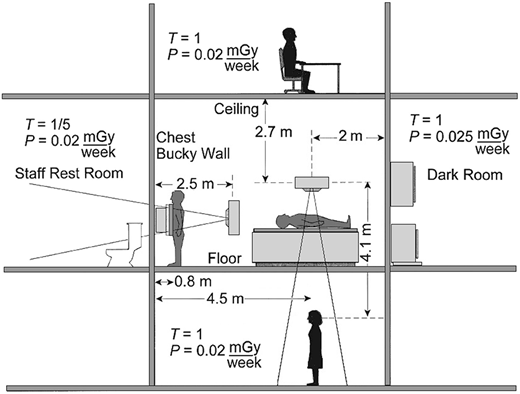
Modeling problem provided by NCRP-147 Report. It shows a Radiographic Room with necessary information for the shielding calculation.
Modeling problem provided by NCRP-147 Report. It shows a Radiographic Room with necessary information for the shielding calculation.
Comparison between the results obtained with the App and the results of NCRP Report N° 147.
| Type of barrier | NCRP-147a | Appa,b |
|---|---|---|
| Floor (primary) | 104.4 mm (concrete) | 104.4 mm (concrete) |
| Ceiling (secondary) | 39 mm (concrete) | 40 mm (concrete) |
| Chest bucky wall (primary) | 1.3 mm (lead) | 1.5 mm (lead) |
| Dark room wall (secondary) | 0.53 mm (lead) | 0.53 mm (lead) |
a It is assumed N = 125 patients per week are radiographed in this room, without considering pre-shielding.
b Basic fields were loaded.
4. Conclusions
The application presented in this paper gives the user the possibility to perform shielding calculations. The barrier thicknesses required to protect areas around a source of X-ray radiation can be easily computed and the effectiveness of an existing barrier can be quickly verified. Based on the optimized and accurate calculation methodology recommended by the NCRP Report N° 147, this app removes some inherent uncertainties and eliminates the overestimation of added shielding thickness which may occur when using other methods already mentioned.
The tools which the application was developed with, allow the application to be adaptable to any device that has a web browser, presenting a user-friendly interface, making its use easy and intuitive.
The computer code showed satisfactory results when compared with the model in NCRP Report N° 147 and can be used as a tool for shielding calculations in X-ray rooms.
This research did not receive any specific grant from funding agencies in the public, commercial, or not-for-profit sectors.
Declaration of Competing Interest: The authors declare that they have no known competing financial interests or personal relationships that could have appeared to influence the work reported in this paper. Publishers note: The publisher wishes to inform readers that the article “Design and development of a web-based application for structural shielding calculation of medical X-ray imaging facilities” was originally published by the previous publisher of Applied Computing and Informatics and the pagination of this article has been subsequently changed. There has been no change to the content of the article. This change was necessary for the journal to transition from the previous publisher to the new one. The publisher sincerely apologises for any inconvenience caused. To access and cite this article, please use Sosa Vera, C., Andres, P. (2022), “Design and development of a web-based application for structural shielding calculation of medical X-ray imaging facilities” Applied Computing and Informatics. Vol. 18 No. 3/4, pp. 235-244. https://10.1016/j.aci.2019.12.002. The original publication date for this paper was 16/12/2019.

