


The processes and factors that underpin the development of effective heave pressure (EHP) at the base of deep excavations in soft soils have been numerically quantified for two idealised soil–structure systems, namely, a building unit cell and a tunnel geometry, using the finite-element method. Charts were developed exploiting dimensional analysis to estimate the impact of normalised time between the end of excavation and the completion of the restraining structure at the base, on the emerging magnitude of EHP for several scenarios where the excavation geometry, ground profile, relative stiffness and retaining wall length were varied. The results of the analyses were in good agreement with available data from physical model tests and the monitoring data of a deep excavation in Gothenburg, Sweden. Complementary analyses of site-specific background settlements and water table levels demonstrate that the charts developed are conservative. The results of this study can, within the limitations of the scenarios studied, readily be used for estimations of EHP in the preliminary design stage, and as a complement to detailed, project-specific analyses.
NOTATION
- B
excavation width
- cv,h
vertical and horizontal coefficient of consolidation, respectively
- D
drainage length
- Einc
increase of Young’s modulus with depth
- Eoed
oedometer stiffness
- Esoil
Young’s modulus of the soil
- EIslab
flexural rigidity of the bottom slab
- H
excavation depth
- kv,h
vertical and horizontal hydraulic conductivity (permeability), respectively
- Lw
retaining wall length
- M
bending moment
- Mcentral
central bending moment of slab
- Mwall
bending moment of slab at location of wall
- OCR
overconsolidation ratio
- R
non-dimensional relative stiffness ratio
- T2D
non-dimensional time factor considering vertical and horizontal consolidation
- Tv
non-dimensional time factor for vertical consolidation
- texc.-slab
time between the end of excavation and placement of structural element
- texcav
time for excavation
- U
average degree of consolidation
- u0
pore pressure prior to excavation
- uexcess,max
maximum excess pore pressure in the finite-element model
- w
self-weight of the structural element
- ymin
depth to bottom of clay layer
- γ, γ′
unit weight, submerged unit weight
- Δv
vertical differential displacement
- δv
vertical displacement
- μi
influence factor considering immediate heave
- v′
Poisson’s ratio
- σ′n
effective stress normal to slab
- σ′n,centr
effective stress normal to slab, central part
- σ′v,h
vertical and horizontal effective stress, respectively
- σ′v0
initial vertical effective stress
INTRODUCTION
Urbanisation and sustainable development drives the increasing need to utilise underground space (Broere, 2016; UN, 2019), calling for accurate predictions of the magnitude of the actions on the structures. Such actions include the temporal evolution of earth pressures on temporary and permanent retaining structures, underground structures and below the base of excavations. While the development of lateral earth pressures on underground and retaining structures in soft soils has been widely studied (e.g. Peck, 1943; Flaate, 1966; Peck, 1969; Finno et al., 2002; Karlsrud & Andresen, 2005; Ng et al., 2012; Whittle et al., 2015; Rouainia et al., 2017; Schweiger & Tschuchnigg, 2021), this is not the case for the development of earth pressures below structures at the base of deep excavations in soft clays.
At the base of deep excavations in soils with a low permeability (hydraulic conductivity) a delayed unloading response is observed (e.g. Symons & Tedd, 1989; Nash et al., 1996; Chan et al., 2018). The negative excess pore pressures (suction) that are initially generated during the excavation, slowly dissipate with time, leading to the heave of the excavation bottom. Considerable loads on the structural elements at the base can be mobilised in situations where this dissipation process has not yet finished at the time of construction of structural elements that restrain the heave. An example is a base slab fixed by tension piles, anchors or heavily loaded columns or walls (Price et al., 1986; Chan et al., 2022a).
The quantification of excavation-induced heave pressures (e.g. Burland & Kalra, 1986) that are restrained by structural elements remains challenging. Simpson (2018) showed that the industry practice outlined in Ingram (2012) for the calculation of earth pressure due to restrained heave is inadequate. Soil–structure interaction effects need to be explicitly incorporated in the design method, to properly assess the effective heave pressure (EHP) acting on the structure due to restrained heave. Hence, the relative stiffness between the structural element and the soil is an important factor in the system response (Chan et al., 2022a, 2022b).
The effect of the time between the end of excavation, and the installation of the structure that restrains the heave, affecting the magnitude of EHP, has not been explicitly studied in prior work. Consequently, in most studies only a single case for normalised time T is investigated. System-level effects, such as the magnitude of excess pore water pressure induced by excavation (Bertoldo & Callisto, 2019) and the geometry of the excavation in relation to the depth of the clay layer (Christian & David Carrier III, 1978), on the temporal development of EHP remain poorly understood. Furthermore, EHP might further evolve during the service life of an underground structure in soft soils with ongoing creep-driven deformations. Clearly, the estimation of EHP depends on many factors including the geometry, soil properties, construction time and the type of restraint (structural elements at the base and sides of the excavation).
This study overcomes the uncertainties in the assessment of the magnitude of EHP and its evolution with time, by developing a set of charts to evaluate EHP. The novelty lies in the extensive automated numerical parametric study, using the finite-element method, designed and evaluated with the aid of dimensionless groups. The results are applicable for a wide range of settings for lightly overconsolidated clays of varying thickness, as well as various excavation geometries, construction time, soil stiffness and permeability. Therefore, the results can readily be used for estimations of EHP in preliminary design stages and as a complement to detailed project-specific analyses.
NUMERICAL QUANTIFICATION OF EFFECTIVE HEAVE PRESSURE
Variables considered and dimensionless groups
The development of EHP at the base of deep excavations is an interaction between the generation of (negative) excess pore pressures during excavation, the subsequent dissipation of pore pressures that result in basal heave and the impact of the structural elements (and their properties) at the base and sides of the excavation. Hence, EHP at the base of excavations in soft soils are impacted by the following factors: (a) the soil–structure interaction that underpins the relative displacement and stiffness between the structure and adjacent soil; (b) the time of placement of the structural restraint after completion of excavation (pore pressure dissipation as a function of normalised time); and (c) the geometry of the excavation in relation to the depth of the clay layer (affecting the ratio of immediate to delayed heave and the subsequent rate of pore pressure dissipation as a function of drainage conditions). In the absence of a comprehensive experimental data set, numerical analyses will be used to conduct a parametric study to investigate the impact of the above factors on the magnitude and temporal evolution of EHP. Furthermore, the complexity of the parametric study is increased sequentially, where the most advanced scenarios capture more advanced soil response and more complex geometries, that is: (a) model geometry, moving from a one-dimensional (1D) building unit cell to a case considering a two-dimensional (2D) excavation for a tunnel (as defined later in the section ‘Numerical model’); (b) soil model, moving from the linear elastic–perfectly plastic Mohr–Coulomb (MC) model, to the SClay1S (Karstunen et al., 2005) and Creep-SClay1S (Sivasithamparam et al., 2015; Gras et al., 2018) models, which are more applicable for soft natural clays. In the scenarios simulating a tunnel geometry, the retaining wall is considered as rigid, and thus only the wall length Lw is varied to control the basal stability of the excavation.
The main driver for EHP is the incomplete dissipation of excess pore pressures that were generated during excavation, at the time that the structural restraint is activated. The magnitude of the generated excess pore pressure is governed by the excavation depth H and the unit weight γ of the excavated soil. The dissipation is controlled by the bulk stiffness and the permeability of the soil, that is, the (vertical) coefficient of consolidation cv, and the drainage length D. Hence, the magnitude of EHP is strongly linked to the time texc.−slab between the end of excavation and the placement of the structural element at the base of the excavation. The time for excavation is idealised in this study, being completed in ≤7 days. The motivation for this assumption was to simulate a short excavation process, resulting in a conservative value for the computed EHP, compared to practical times for excavation processes within deep excavations.
The deflection of the structural element, considering here a bottom slab, at the base of the excavation (due to EHP and water pressure) is controlled by the span B and the rigidity EIslab of the slab relative to the stiffness of the soil Esoil. From the above reasoning and idealisations, EHP is considered to be dependent on the following variables:
which can be further arranged into the following dimensionless groups:
It should, however, be noted that the total (effective) rigidity of the structural restraint may increase progressively during construction, and depends on the type of sub- and superstructure, including the location of walls within the slab (Brown & Yu, 1986; O’Brien et al., 2012).
EHP is considered as an earth pressure in addition to any permanent water pressure. Therefore, EHP should be related to a portion of γH-u0, that is σ′v0 at the excavation level. For a rigid structure, the upper limit of the uplift pressure would be the vertical effective stress at that level prior to excavation. Equation (2) then becomes
The left-hand side of equation (3) is the EHP ratio, the first term of the right-hand side is a relative stiffness ratio, R, and the second term is the normalised time, or time factor Tv. Some aspects of the excavation and loading history in the soil will further impact the EHP. Hence, in addition to the variables in equation (3), the parametric study will generalise the effect of: (a) varying the increase of soil stiffness with depth; (b) excavation stability by varying the retaining wall length; (c) varying the self-weight of the structural element; (d) background settlements; and (e) the location of the groundwater table.
Numerical model
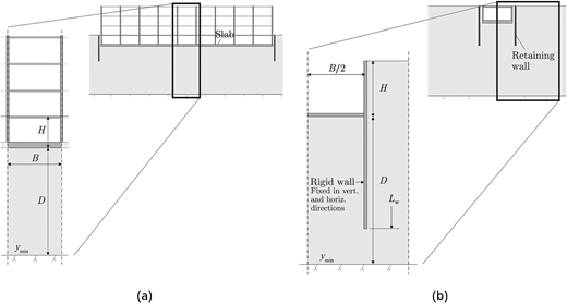
Two idealised soil–structure systems are studied in the finite-element analysis, see Fig. 1. In the first case, a plane strain building unit cell (BUC) is considered, where the impact of the retaining wall and the extent of the excavation are not considered. In the second idealisation of a tunnel geometry, the retaining wall is also incorporated. The slab is modelled as a plate element with a linear elastic constitutive model considering the intact stiffness of the concrete (ignoring cracks). Once activated, the element is fixed (clamped) at the model boundaries in the BUC. For the tunnel geometry, the simulations are restricted to a rigid slab. This aids in isolating the impact of more realistic soil conditions (impact of soil model, background settlements and location of the groundwater table). In reality, the EHP and any water pressure are likely to mobilise some upward displacement of the structure. As a result, these idealisations contribute to conservative outputs of computed EHP. To normalise the structural response from EHP, the bending moment M in the BUC is normalised to
The heave δv of the structural element or the base of the excavation in the BUC is also normalised to
where δv is the vertical displacement; Esoil in the unit cell geometry is the constrained oedometer modulus; Eoed, derived from Eoed = Esoil(1 – v′)/((1 + v′)(1 – 2v′)) with v′ = 0·2. For the tunnel geometry the (effective) Young’s modulus Esoil is used. The retaining wall and the vertical model boundaries are modelled as impermeable. The lower model boundary, as well as the interface at the excavation base and structural element, are considered as permeable. The motivation for the latter idealisation is that in practice a coarse-grained layer is typically used to level the excavation base before casting of a concrete slab.
Constitutive models
Analyses are initially carried out using the linear elastic–perfectly plastic MC model. Table 1 provides the parameter values used for the clay deposit and the top layer of fill material (thickness of 1 m unless stated otherwise). Subsequently, the SClay1S and Creep-SClay1S models are used, to represent the emerging response of a lightly overconsolidated natural clay. Specifically, the latter model allows the effect of background creep settlements on the evolution of EHP to be quantified. Table 2 summarises the values for the model parameters used in this study for a representative Swedish soft sensitive clay (Tornborg et al., 2021).
The coefficient of earth pressure at rest, K0, is set to 0·6 and for the SClay1S and Creep-SClay1S models, the overconsolidation ratio, OCR = 1·3. The permeability of the soil is varied in the parametric study; however, it is idealised as uniform and isotropic. For the simulations using the MC model, the interfaces between the clay and the structural elements are modelled with an interface factor, Rinter = 0·5. For the SClay1S and Creep-SClay1S models, the interfaces are modelled assuming full friction with ϕ′ = 35° and c′ = 1 kPa. The effect of the slab interface material on the magnitude of the EHP was investigated by running simulations with the Creep-SClay1S model (tunnel geometry with H = 10 m) adopting the MC material interface settings. The computed EHP increased by a factor of 1·002–1·005 (maximum difference 0·5 kPa) when using the MC interface, suggesting a negligible impact on the results.
Finite-element analyses
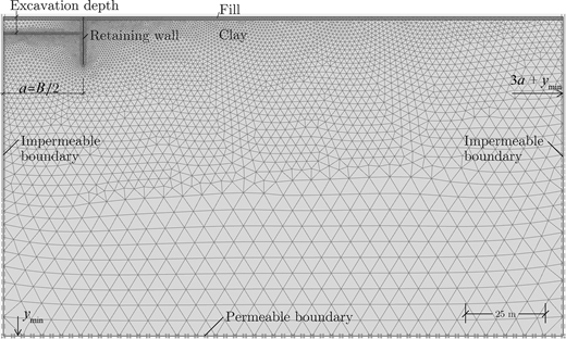
The calculation phases are outlined in Table 3. Simulations involve groundwater tables located at (a) the excavation base and (b) at 1 m depth below ground level. For situation (a), the analyses are performed using a decoupled consolidation analysis (‘Consolidation’ calculation type in Plaxis 2D version 21·01·00·479). For situation (b), fully coupled analyses are performed to accommodate a temporary groundwater lowering and change of steady state pore pressures during the construction stage. In all cases the soil is considered as fully saturated with no suction cut-off. Table 4 presents an overview of the simulated scenarios in the parametric study and the range for the parameter variation. Scenarios 1 and 2 concern the BUC considering a weightless slab and a slab with a self-weight of 25 kPa, respectively. Scenarios 3–6 concern the tunnel geometry and quantify, for example, the effect of soil model, background settlements and a high groundwater table on the computed EHP. The MC model is used in scenarios 1–3 and the SClay1S and Creep-SClay1S in scenarios 4–6. A representative finite-element mesh used in this study is illustrated in Fig. 2.
RESULTS AND DISCUSSION
Building unit cell – MC model
Impact of normalised time and relative stiffness
First, a simple scenario of the BUC involving a weightless slab, and a groundwater table located at the excavation base, is analysed with the MC model (i.e. scenario 1 in Table 4). The following findings for the soil–structure response and development of EHP can be observed.
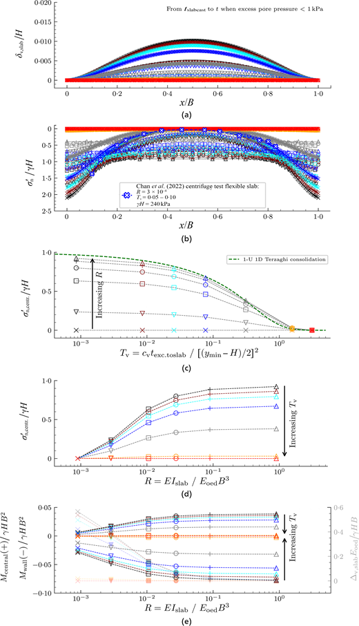
The hogging displacement of the slab (Fig. 3(a)) increases with decreasing normalised time T and relative stiffness ratio R. This is reflected in the distribution of the action, EHP, along the slab (Fig. 3(b)). For low R, EHP will be non-uniform with the fixed edges of the slab attracting load from the central part. For R < 0·1 this results in EHP at the location of the wall being higher than the in situ vertical effective stress. For illustration, centrifuge test results (for a flexible slab (Chan et al., 2022b)) are normalised and included in Fig. 3(b).
Figure 3(c) shows that the dissipation of EHP with T is a process of reversed consolidation settlement. In this figure, 1 − U illustrates an analytical solution (Muir Wood, 2009) to Terzaghi’s theory of 1D consolidation.
Figures 3(c) and 3(d) quantify how EHP at the centre of the slab reduces with increasing T and/or decreasing R.
In addition to EHP in any part of the slab, the structurally more relevant bending moment is also computed. Fig. 3(e) quantifies the wall and central moment as a function of R and T. The decrease in bending moment comes at the expense of increasing differential slab displacements (indicated by the shaded results, plotted against the vertical axis on the right).
Impact of excavation depth and self-weight of the slab
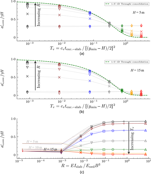
Figure 4 extends on the previous results by introducing the effect of a self-weight, w, of the slab.
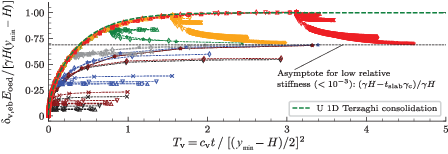
A slab with w = 25 kPa is considered for H = 5, 10 and 15 m, to generalise this effect in relation to H. Fig. 5 illustrates for H = 5 m the normalised displacement of the excavation bottom and slab plotted against the normalised time. Combined, Figs 4 and 5 provide the following insights.
For low R (≤10−3), the minimum vertical earth pressure corresponds to the self-weight.
For high R (>10−1) the slab is able to bridge across the supports and does not impose any pressure.
If the heave has dissipated before the slab is cast, the self-weight may result in settlement (sagging) of the slab in systems with low R. To estimate the displacement pattern (sagging, or hogging due to EHP) one can study when the computed results intersect the illustration of 1 − U, that is at T = 0·4 and 0·9 for H = 5 and 15 m in Figs 4(a)−4(b).
For low R, the long-term normalised displacement of the excavation bottom and slab approaches an asymptotic value, annotated in Fig. 5 for H = 5 m.
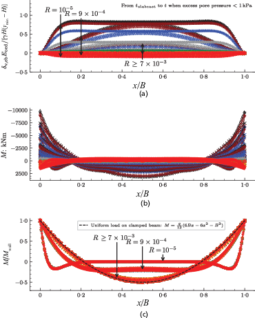
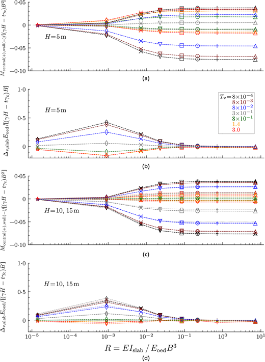
Figure 6(a) exemplifies the displacement of the slab when H = 15 m and Fig. 6(b) the distribution of the bending moment M for H = 5, 10 and 15 m. The intention here is not to illustrate distinguishable results of individual simulations, but rather to demonstrate that the results fall in place when normalised, as in Fig. 6(c), presenting the normalised bending moment ratio M/Mwall along the slab for H = 5, 10 and 15 m. For R ≥ 7 × 10⁻³, the system resembles the behaviour of a rigid beam with uniform load, R = 9 × 10⁻⁴ behaves intermediate and R = 10−5 as ‘flexible’ (centre of slab being flat). The absolute bending moments along the slab can be obtained by multiplying the normalised bending moment ratio with Mwall from Fig. 7. In Fig. 7, H = 5 m is separately plotted from H = 10 and 15 m, given for H = 5 m the slab self-weight results in marked settlement for T > 3 × 10⁻¹ and larger bending moments (in sagging) compared to H = 10 and 15 m.
Tunnel geometry
Three considerations arise when moving from the BUC to the tunnel geometry: (a) the proportion of the immediate to total heave is affected by the geometry of the excavation and the clay layer – in a similar way to the settlement influence factors for shallow foundations; (b) the consolidation of excavation-induced excess pore pressures is no longer 1D; (c) the reduced basal stability of the excavation contributes to heave and thereby affects the excess pore pressures.
Impact of system geometry: influence factor and 2D consolidation
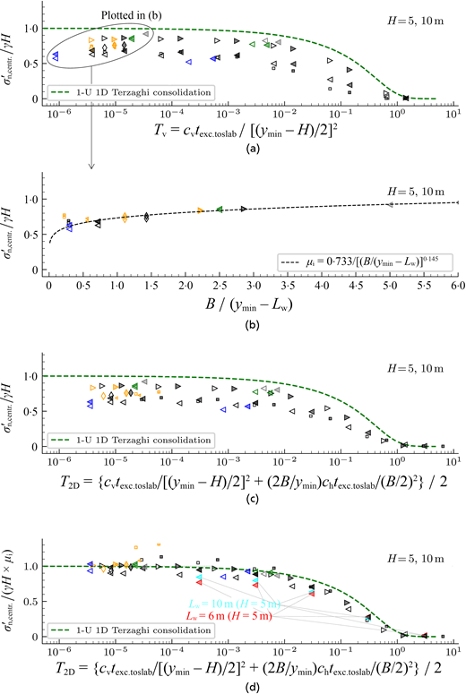
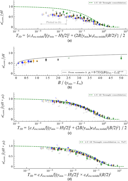
Figure 8 shows the predicted EHP at the centre of a rigid restraint. The results have been normalised to the stiffness in the midpoint of the clay layer (between the excavation base and lower model boundary). As opposed to the BUC, the EHP ratio does not converge to 1 for small values of T, considering that, in a 2D problem, a portion of the heave occurs immediately due to shear strains in the soil during excavation. The magnitude of instant heave vanishes as the problem converges to conditions that are similar to the case of the BUC. Results from the simulations with small T are replotted in Fig. 8(b) to highlight this geometry effect. Clearly, the ratio of excavation width to the depth of the clay layer influences EHP, and an influence factor μi is proposed for normalisation. In Fig. 8(c), the results of Fig. 8(a) are replotted using a different expression for the normalised time that includes a horizontal component, that is:
The improved normalisation of the results for 2D effects using T2D according to equation (6) (setting ch = cv), and the influence factor μi, are shown in Fig. 8(d).
Impact of retaining wall length
Two outliers are evident in Fig. 8(d) with the normalised EHP ratios of approximately 1·3. These outliers are simulations for H = 10 m, B = 10 m with Lw = 30 m. In this case the system represents a narrow deep excavation (B < Lw) and approximates the 1D BUC case. The opposite case, that is short walls leading to reduced basal stability, are exemplified in Fig. 8(d) for H = 5 m with EHP ratios reducing by a maximum of 20%. For large T, smaller negative excess pore pressure remain to be dissipated. Hence, the EHP ratio at the centre of the slab is not significantly affected. The loss of stability may, however, create an upward earth pressure close to the retaining wall. This effect is, however, not studied in the current paper, but can be considered as a reversed bearing capacity problem.
Impact of soil model
The SClay1S and Creep-SClay1S models enable the behaviour of natural clays to be captured (Karstunen et al., 2005; Sivasithamparam et al., 2015; Gras et al., 2017) more accurately than the MC model. A major difference to the MC model is that the stiffness is anisotropic and stress dependent; furthermore, Creep-SClay1S accounts for rate-dependency. Fig. 9 presents the results of the tunnel geometry (scenario 3) re-analysed with SClay1S and Creep-SClay1S. Note, the groundwater table is (still) located at the excavation base. The results have been normalised using the initial stiffness in the midpoint of the clay layer. For the Creep-SClay1S results, the plotted EHP is the computed maximum value during the service life (as the earth pressures beneath the slab are evolving due to consolidation and rate-dependency). The results of the SClay1S model and maximum values computed by the Creep-SClay1S model are similar, also in comparison to the results using the MC model (scenario 3). The Creep-SClay1S model, however, allows the effects of rate-dependency (such as creep and relaxation) to be incorporated. The long-term (120 years) values computed by the Creep-SClay1S model are included in Fig. 9 as lightly shaded grey markers. As seen in Fig. 9(b), the long-term reduction of EHP clearly depends on the width of the excavation in relation to the depth of the clay layer. The effect of rate-dependency on long-term EHP is discussed further in section ‘Impact of background settlements’.
COMPARISON TO PHYSICAL MODEL TESTS
The validity of the previously presented charts is assessed against well-documented physical model tests (Chan et al., 2022a). Furthermore, this section serves as a worked example for their use. The model tests were performed at 100g in a geotechnical centrifuge. The tests modelled a 15 m deep excavation in a 16 m deep overconsolidated (OCR of 2–3) clay layer overlain by 15 m of sand. The groundwater table was located at the excavation base. Table 6 in the Appendix specifies the prototype conditions, the evaluated parameters and the values of dimensionless groups for the benchmarking of the finite-element parametric study. Table 5 presents the EHP ratio and the normalised bending moment derived using the previously presented charts, compared to the physical model tests. The comparison is complicated by a load imposed on the basement walls 15 weeks after excavation in the model test. The 22 MN load equals 49 kPa if the load was to be distributed equally in the basement box. This caused the slab to settle (Fig. 8(b) in Chan et al. (2022a)). Hence, after imposing the load it is unlikely that the slab contact pressure and bending moment are purely due to EHP. The reported central EHP ratio before load application was 0·45, and the normalised central moment was 0·022. The long-term results were included in Chan et al. (2022b), reporting an EHP ratio of 0·57, and the normalised central moment of 0·039. The agreement between the results of this parametric study and the model test is good until load application, but deviates in the long term. This suggests that the long-term observations in the physical model test are not purely due to EHP.
SITE-SPECIFIC CONDITIONS
Impact of background settlements
The charts in Figs 3–9 have been developed in a manner to avoid site-specific conditions. In deposits of soft clay with (historic) fills, however, background creep settlements are common. A representative (simplified) case in central Gothenburg, Sweden, is used to show the implication of background creep on the development of EHP. Here the ongoing settlements stem from historic land reclamation works, approximately 200 years ago, on the deep deposit of soft sensitive clay (for details see Tornborg et al. (2024)). The construction of 2 m of fill on top of the clay layer is simulated (a 1 year phase) followed by 200 years of consolidation, to initialise the settlement rates prior to excavation. Then, calculation phases as previously described (Table 3) are applied.
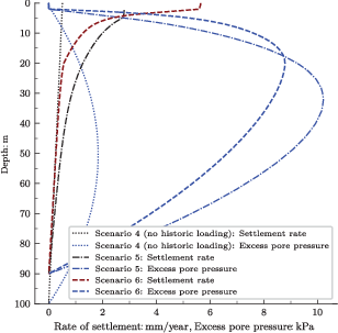
Figure 10 presents the computed settlement rate and the excess pore pressures in the clay deposit prior to construction for two scenarios (data on the previously presented scenario 4 are also included). In scenario 5 the groundwater table is located at the excavation base, whereas for scenario 6 (presented in the next section), it is located at 1 m depth below the ground level.
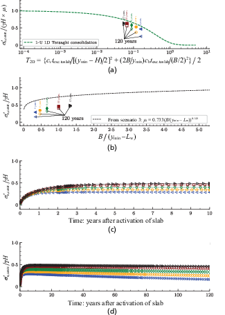
Figure 11 presents the computed EHP for five different excavation widths, with the maximum EHP occurring 5–10 years after casting of the slab. The wider the excavation, the longer the time to reach maximum EHP. The narrower the excavation, the greater is the long-term reduction of EHP due to background settlements. This scenario is, however, site specific and is only intended to demonstrate the effect of background settlements on the evolution of EHP. In summary, the maximum EHP was practically unaffected, while the long-term EHP may reduce notably due to ‘down drag’.
Impact of a natural groundwater table
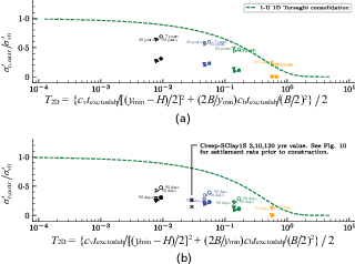
When developing the charts, the simulations were conducted with a groundwater table located at the excavation base, to isolate a conservative limit for the mechanism of EHP development. Compared to a more representative soft clay deposit with a groundwater table located a few metres below ground level, this introduces two oversimplifications for: (a) the effective stress response and hence soil stiffness and strength, and (b) the effect of groundwater lowering during the construction stage, as well as the subsequent regain of water pressure below the slab. Therefore, scenario 4 (without historic loading) is reanalysed with a groundwater table located at 1 m depth below ground level. Fig. 12 presents the results using the SClay1S model. In Fig. 12(a), the water pressure is set to start regaining 10 years after construction of the slab. The development of stress due to EHP is therefore allowed to proceed without being compensated by any increase in water pressure. The results of the maximum EHP in Fig. 12(a) are similar to scenario 4. The 120 years values represent the situation when the water pressures have returned and thus reduced the effective stresses.
For the results shown in Fig. 12(b), the groundwater table is set to start regaining 90 days after construction of the slab. The evolution of EHP is compensated by the increase in water pressure. This is shown by the drop in maximum values compared to Fig. 12(a). The long-term stress (after 120 years) is, however, similar to that in Fig. 12(a). In addition, it should be emphasised that the design of a slab does not concern the shift of a portion of the EHP to water pressure but rather the total pressure exerted by water pressure and an additional EHP.
Comparison to field monitoring data
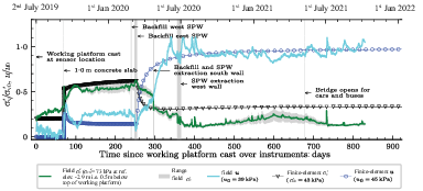
One simulation in Fig. 12 (see annotation) was analysed using the Creep-SClay1S model with a loading history as in scenario 5 (see scenario 6 in Fig. 10 for the computed settlement rate prior to construction). In this simulation an excavation depth H = 5 m, a span B = 20 m in a ymin = 90 m deep clay deposit is assumed. The time between the end of excavation and construction of the slab texc.−slab = 70 days. Pouring of the wet concrete for the slab is simulated by applying a line load for 1 day before activating the slab element. The regain of water pressure is simulated to start at 180 days after casting of the slab. This resembles a specific case involving recent field monitoring of the hydro-mechanical response of soil elements below an excavation bottom in soft sensitive clay. The details of the instrumentation and the complete field monitoring data on the evolution of in situ stresses are presented in Tornborg et al. (2024).
The general trends of the computed response are corroborated by the monitored in situ response, as presented in Fig. 13. Some discrepancies are, however, noted. From day 0 to day 70, the measured increase in effective stress is partly due to a decrease in pore pressure. During casting of the slab, the computed increase in pore pressure is slightly less than observed. The discrepancy in computed and observed pore pressures during days 100–250 is attributed to varying dewatering activity within the pit. At day 295 there is a sudden drop in the measured vertical effective stress which offsets the measured and computed response. The general trend of the computed response is, however, satisfactory and provides partial validation of this study.
CONCLUSIONS
This paper addresses the need for a systematic study on the development of EHP at the base of deep excavations. An extensive numerical parametric study was conducted, using the finite-element method, to study the impact of normalised time T, relative stiffness R, geometry of the excavation in relation to the depth of the clay layer, retaining wall length, background settlements and location of the groundwater table, on EHP. Charts were developed using dimensionless analysis to estimate the impact of normalised time T between the end of excavation and the completion of the restraining structure at the base on the emerging magnitude of EHP for several scenarios.
Two geotechnical engineering systems of increasing complexity were studied. In addition, the complexity of the constitutive model was increased, to capture the features of natural soft clays more accurately. The scenarios studied were designed to yield a conservative value for the computed EHP; that is, the idealised supports were fully fixed once the slab was activated (i.e. zero uplift). It was shown that for flexible systems with R < 0·1, the ratio EHP/σ′v0 may be greater than 1·0 if stiff supports/walls attract load from the mid-span. Normalised bending moments were presented as a function of T and R, enabling assessment of the imposed bending moment along the slab. For narrow excavations compared to the depth of the clay layer, it was shown that the EHP ratio decreases, with a minimum influence factor 0·4, purely due to geometry effects. Furthermore, as the width of the excavation reduces, it was shown that introducing a horizontal component to Tv enables the effects of 2D consolidation to be generalised. Reducing the retaining wall length imposed a maximum 20% reduction of EHP ratios.
The effects of background settlements were examined with the rate-dependent Creep-SClay1S model and it was demonstrated that, although the maximum value for EHP remains nearly unaffected, the long-term EHP reduces notably for narrow excavations due to ‘down drag’. Furthermore, for a groundwater table located above the excavation base, it was shown that the returning water pressure (after dewatering) under the slab reduces the long-term EHP.
The results of the individual FE analysis and normalised charts were in good agreement with the relevant physical model tests and field monitoring data. The results of this study can, within the limitations of the scenarios studied, readily be used for estimations of EHP in preliminary design stages and as a complement to detailed project-specific analyses.
ACKNOWLEDGEMENTS
The financial support provided by Skanska, SBUF (development fund of the Swedish construction industry, grant 13995), BIG (Better Interaction in Geotechnics, grant A2021-06, from the Swedish Transport Administration) and Formas (grant 2019-00456) are gratefully acknowledged. The work was done as part of Digital Twin Cities Centre, which is supported by Sweden’s Innovation Agency VINNOVA under grant no. 2019-00041. Finally, the authors would like to thank Dr Ayman Abed (Chalmers University of Technology), Dr Anders Kullingsjö and Dr Torbjörn Edstam (both at Skanska Sweden AB) for their valuable comments during the progress of this work.
REFERENCES
APPENDIX. SUMMARY OF PHYSICAL MODEL TEST
Table 6 summarises a physical model test (Chan et al., 2022a) as well as the evaluated parameter values and non-dimensional groups for the comparison presented in the section ‘Comparison to physical model tests’.
Discussion on this paper closes 1 May 2026; for further details see p. ii.
 ), 100(▷)

