

The shaking table is a good reproduction of the structure response test method in the laboratory. This paper explores the shaking or vibration table from the aspects of construction, control technology, test method and application. The construction time of a typical shaking table in China and around the world is given, and the indicators such as table size and performance parameters are hereto summarised. This paper expounds the significance of the construction of the shaking table, analyses its development and the advantages and disadvantages of its control technology, and discusses its existing mainstream test methods and application process. The application of the shaking table technology in related research fields is introduced in detail. This provides a reference for the further selection, upgrade, development and utilisation of seismic research simulation of shaking table.
1 Introduction
It is well-known that earthquake is one of the most dangerous disasters on earth, making seismic research urgent. According to Huang (2008), seismic test is the most important step in seismic research. The shaking table test is favoured by researchers because it can effectively reproduce seismic waves on the table during the experimental process and intuitively understand the seismic performance of structures. Nowadays, the type and size of the shaking table have changed greatly. Control technology has developed from classical analogue control to intelligent control. However, due to the performance difference of the internal components of the shaking table and other factors, the reproduction accuracy of the shaking table waveform is limited (Tang et al., 2009). To further promote the overall stability of a shaking table, to increase its robustness in the process of experiment and to improve the precision of mesa waveform reproduction, some scholars, in recent years, have studied in detail the dynamic characteristics of its main components, performance parameters, interaction, and so on. They have established a powerful control theory research system for the shaking table system. Shaking tables have also been widely applied in various fields of seismic research direction. In view of the limited literature on the construction, control, application and development of shaking tables in China and internationally, this paper will comprehensively analyse and summarise the shaking table from the aspects mentioned here according to existing relevant information, so as to provide reference for the further development of research on shaking tables in the future.
2 Construction of a shaking table
2.1 International construction conditions
The shaking table was developed in Japan and in the United States in the mid-1960s (Huang, 1986; Wang, 2009; Williams, 2001). The development of early Japanese and American shaking tables is shown in Table 1. With the deepening of seismic research, it has become inevitable to develop large vibration tables and vibration systems. Studies on the large-scale and multiple arrays of typical shaking tables internationally are shown in Table 2. The E-Defense shaking table (Ling, 2008) is shown in Figure 1, which has a maximum load of 1200 t, a maximum displacement of ±1000 mm and a power output of up to 6000 kN.
The early development of shaking tables in Japan and USA
| Time (year) | Developer | Platform dimension: m | Direction | Contribution | Reference |
|---|---|---|---|---|---|
| 1966 | Institute of Production Technology, University of Tokyo | 10 × 2 | X | The world’s first | Huang (1986) Wang (2009) Williams (2001) |
| 1968 | University of Illinois | 3.65 × 3.65 | X | The United States’ first | |
| 1970 | Japan’s National Disaster Prevention Center | 15 × 15 | X or Z | The world’s first biggest (from 1970 to 2020) | |
| 1971 | University of California, Berkeley | 6.10 × 6.10 | X, Y | World’s first two-way machine | |
| 1984 | Mitsubishi Corporation | 6 × 6 | X, Y, Z | The three-parameter control technology is used for the first time |
Study on the large-scale and multiple arrays of typical shaking tables outside China
| Time (year) | Development organisation | Platform dimension: m | Direction | Significance |
|---|---|---|---|---|
| 1979 | Institute of Civil Engineering, Ministry of Construction, Japan | Four series of 3 × 2 | X | The earliest array system in the world |
| The 1990s | The French Laboratory of Seismic Mechanic Studies | 7.60 × 7.60 | X, Y, Z | The largest shaking table in Europe in the twentieth century |
| University of California San Diego | 7.60 × 12.20 | X | The world’s first and largest outdoor shaking table | |
| 2003 | University of Nevada, Reno, USA | Three series of 4.30 × 4.50 | X, Y | The first two-way vibration system in the United States |
| 2005 | NIED with the Department of Science and Technology, Japan | 20 × 15 | X, Y, Z | The largest single shaking table in the world (‘E-Defense shaking table’ for short) |
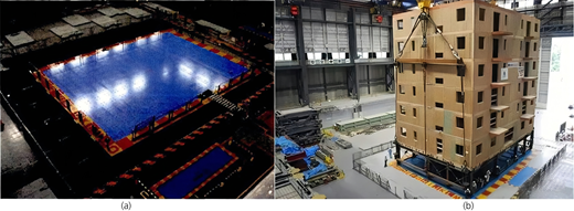
Shaking table and seismic experimental research site: (a) the shaking table and (b) the model
Shaking table and seismic experimental research site: (a) the shaking table and (b) the model
2.2 Domestic construction situation
Research on shaking tables started relatively late in China, and relevant research progress of the early shaking table in China is shown in Table 3. The typical Chinese seismic simulation vibration tables before the year 2000 is summarised in the work of Gao et al. (2014). Since the beginning of the twenty-first century, the research on large-scale shaking tables and array systems in China has also been in full swing. The relevant construction situation is shown in Table 4.
Research progress of shaking tables in China
| Time (year) | Achievement |
|---|---|
| 1969 | The first special shaking table for the national defense system was successfully built. |
| 1986 | A 3 × 3 m single horizontal vibration table with double shakers was developed. |
| 1988 | A 5 × 5 m double horizontal seismic simulation shaking table was successfully developed. |
| 1997 | The Institute of Engineering Mechanics of China Earthquake Administration and Harbin Institute of Technology jointly and successfully developed a 5 × 5 m three-way 6 degrees of freedom shaking table. |
The construction status of typically large shaking tables and array systems in China since the twenty-first century
| Time (year) | Development organisation | Direction | Mesa dimension: m | Load: t | Maximum displacement: mm | Maximum speed: mm/s | Maximum acceleration: g | Frequency range: Hz |
|---|---|---|---|---|---|---|---|---|
| 2004 | Institute of Earthquake Engineering, China Academy of Building Research | X, Y, Z | 6.10 × 6.10 | 60 | X: ±150 Y: ±250 Z: ±100 | X: ±1000 Y: ±1200 Z: ±800 | X: ±1.5 Y: ±1.0 Z: ±0.8 | 0.1–50 |
| 2006 | Beijing University of Technology | X | 1.00 × 1.00 (9) | 9 × 10 | X: ±75 | X: ±600 | X: ±1.0 | 0.4–50 |
| X, Y, Z | 2.50 × 2.50 (2) | 2 × 10 | X: ±125 Y: ±125 Z: ±100 | X: ±600 Y: ±600 Z: ±500 | X: ±2.0 Y: ±2.0 Z: ±2.0 | 0.1–50 | ||
| 2008 | Fuzhou University | X, Y | 4.00 × 4.00 2.50 × 2.50 (2) | 22 10/table | X: ±250 Y: ±250 | X: ±750 Y: ±1050 | X: ±1.5 Y: ±1.2 | 0.1–50 |
| 2011 | Tongji University | X, Y | 4.00 × 6.00 (4) | 30/table 70/table | X: ±500 Y: ±500 | X: ±1000 Y: ±1000 | X: ±1.5 Y: ±1.5 | 0.1–50 |
| 2013 | Central South University | X, Y, Z | 4.00 × 4.00 (4) | 30/table | X: ±250 Y: ±250 Z: ±160 | X: ±1000 Y: ±1000 Z: ±1000 | X: ±1.0 Y: ±1.0 Z: ±1.6 | 0.1–50 |
| 2015 | Chongqing University | X, Y, Z | 5.10 × 6.10 | 60 | X: ±250 Y: ±250 Z: ±200 | X: ±1200 Y: ±1200 Z: ±1000 | X: ±1.5 Y: ±1.5 Z: ±1.0 | 0.1–50 |
| 2017 | Southwest Jiaotong University | X, Y, Z | 10.00 × 8.00 | 160 | X: ±800 Y: ±800 Z: ±400 | X: ±1200 Y: ±1200 Z: ±830 | X: ±1.2 Y: ±1.2 Z: ±1.0 | 0.1–50 |
| X, Y, Z | 3.00 × 5.00 | 30 | X: ±400 Y: ±400 Z: ±400 | X: ±1800 Y: ±1800 Z: ±1500 | X: ±2.0 Y: ±2.0 Z: ±1.5 | 0.1–50 | ||
| X, Y, Z | 3.00 × 6.00 | 30 | X: ±400 Y: ±400 Z: ±400 | X: ±1800 Y: ±1800 Z: ±1500 | X: ±2.0 Y: ±2.0 Z: ±1.5 | 0.1–50 | ||
| 2019 | Hohai University | X, Y, Z | φ: 5.75 (in water) | 20 | X: ±150 Y: ±150 Z: ±100 | X: ±1000 Y: ±1000 Z: ±800 | X: ±2.0 Y: ±2.0 Z: ±1.33 | 0.1–100 |
| 2019 | Tianjin University | X, Y, Z | φ: 3.60 (2) (in water) | 20/table | X: ±300 Y: ±300 Z: ±200 | X: ±1000 Y: ±1000 Z: ±800 | X: ±1.5 Y: ±1.5 Z: ±1.2 | 0.1–100 |
| 2021 | Tianjin University (constructing) | X, Y, Z | 20.00 × 16.00 | 1350 | — | — | X: ±1.5 Y: ±1.5 Z: ±2.0 | — |
| 2021 | Southeast University (constructing) | X, Y, Z | 6.00 × 9.00 | 120 | X: ±500 Y: ±500 Z: ±300 | X: ±1500 Y: ±1500 Z: ±1200 | X: ±1.5 Y: ±1.5 Z: ±1.0 | 0.1–50 |
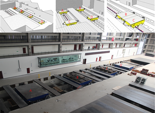
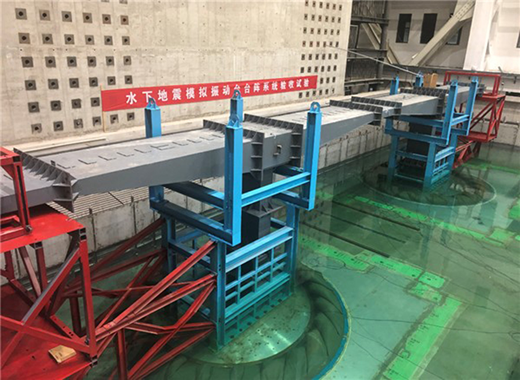
The multifunctional shaking table test system built by Tongji University is shown in Figure 2. Four desks can synthesise a large linear shaking table group and can also be two parallel syntheses of a large rectangular shaking table group. Two main platforms (B, C) can also be integrated into a large vibration table as a single vibration table based on the shaking table laboratory information sharing service platform of Tongji University (2021). The underwater shaking table system of Tianjin University is the world’s first underwater three-directional 6 degrees of freedom twin shaking table array as shown in Figure 3 (Zhao and Chen, 2019). Tianjin University’s large shaking table system will surpass ‘E-Defense’ to be the largest in the world once completed.
3 Shaking table control technology
3.1 Traditional control and improvement methods
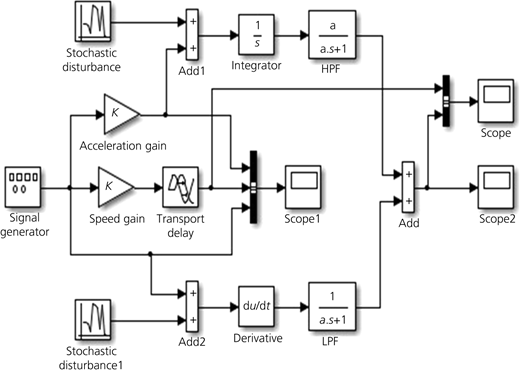
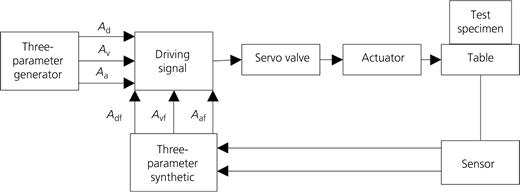
The traditional shaking table control method is mainly divided into displacement control-based PID control and ‘three-parameter control’ and is reviewed in the works of Cai (2018) and Wan et al. (2012). By comparing the simulation results of PID control and three-parameter control, Chen and Zhang (2013) pointed out that the three-parameter control technology can effectively increase the system damping ratio and prevent excessive resonance damage of specimens, and can also increase system stability. Also, some scholars (Gao et al., 2014; Luan et al., 2014a, 2014b; Tagawa and Kajiwara, 2007; Wang et al., 2007; Xu et al., 2008; Yang et al., 2007) also conducted in-depth studies on the three-parameter control technology successively. Ji et al. (2012) solved the inconvenience in the design and application of an analogue speed synthesiser and developed a new type of speed synthesiser. The simulation model of the synthesiser is shown in Figure 4.
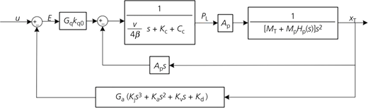
For the problem of parameter tuning in three-parameter control, a ‘three-parameter improved control algorithm’ based on the combination of three-parameter feedforward and feedback is proposed in Luan et al. (2014a, 2014b), which effectively eliminated the poles close to the virtual axis in the closed-loop transmission function of the system and widened the system bandwidth. The principal diagram is shown in Figure 5. Li et al. (2018) introduced acceleration feedback into the improved three-parameter control algorithm, enlarging the system bandwidth to 0.35–64 Hz. The transmission function is shown in Figure 6.
3.2 Intelligent control algorithm
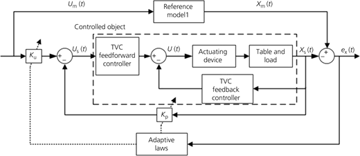
Since the 1970s, iterative algorithm has been applied to the control of seismic simulation shaker (Tang et al., 2009). The three-parameter control technology based on linear iterative correction could better reproduce the acceleration time history. However, the pre-test will cause some damage to the specimen. Then the adaptive control algorithm was born; this algorithm can eliminate the disadvantage of non-adjustable parameter ratio in traditional control without needing to master the mathematical model of the controlled object, and it has a better fault tolerance ability. The model reference adaptive control (MRAC), adaptive inverse control and other algorithms are derived (Zhang et al., 2013). Tian et al. (2012) proposed an improved adaptive control test method, which can identify the system transmission function in real time and directly obtain the initial system transmission function, thus avoiding the damage caused by the specimen pre-test, and having strong tracking ability and anti-interference ability. Cai (2018) also proposed a dual-loop control algorithm combining MRAC and three-variable control (TVC), as shown in Figure 7. This algorithm increases the robustness of the system and reduces tracking error. It also weakens the adverse transient response caused by the change of initial parameters to the system, accelerates the convergence speed, widens the bandwidth and improves the stability of the system.
Besides the control algorithms, other forms of intelligent control algorithms have been gradually applied to the field of shaking table control. Peng (2018) proposed a neural control method based on wavelet network and applied it to the control research of turntable servo system. The results show that the method can effectively improve the accuracy of the controlled system. Soleymani et al. (2019) designed a fuzzy sliding mode supervisory controller for a shaking table with a variable load. The controller consists of a proportional interval latent rule controller and a fuzzy-sliding mode monitoring controller. The experimental results show that the controller has good and robust tracking performance under harmonic and seismic excitation with parameter uncertainties.
For the parameter tuning and error compensation control system, many scholars have done in-depth research. Ji et al. (2014) proposed a self-tuning method for the control parameters of a shaking table based on his expert experience. By comparing it with the time-domain characteristics of the theoretical calculation parameter tuning method, the results show that this method is simplified and effective. A series of studies on the influence of specimen characteristics on system control performance had been conducted (Li et al., 2010; Li et al., 2019; Tang et al., 2010), and pointed out that the system had the best stability under the control of no-load design parameters, but the reproduction accuracy of input wave would be reduced to varying degrees near each order frequency point of the specimen. Therefore, a real-time reaction compensation algorithm was designed to correct the adverse effects caused by the interaction between the test piece and the mesa. Wang and Lei (2020) achieved the high-precision reproduction of shaking table waveform by using linear active disturbance rejection control (LADRC). The problem of optimisation and adjustment of relevant parameters are successfully solved (Yan et al., 2016b; Xu et al., 2017) by adopting the control method of artificial fish swarm algorithm and PID neural network.
4 Test method and technical application of the shaking table
4.1 Shaking table test method
The shaking table test methods can be generally divided into two categories: substructure test method (including substructure hybrid test) and integral model test method.
Nakashima et al. (1992) published the research results of real-time substructure test of the shaking table for the first time; real-time substructure test has both the advantages of quasi-dynamic substructure test and the advantages of simulating actual earthquake action. Reinhorn et al. (2005) proposed the hybrid test method of the vibration table substructure, formulated the substructure division principle and accurately formulated the unified formula. Wang and Pan (2018) summarized the main problems in the development process of substructure hybrid test in the past three decades, and proposed the solution of “Internet +” mode, which can maximize the ability and accuracy of substructure hybrid test. “Internet +” means to connect multiple laboratory resources and realize the refinement of the “third-generation extensible substructure hybrid test platform” through finite element software simulation.
The scale model test is often used in the overall structure test of the shaking table, and for such a test, it is necessary to consider dynamic similarity ratio design, model similarity requirements, model similarity constant, and so on. Zhang (1997) studied and created a set of ‘uniform similarity law’ for seismic simulation tests. Shen and Qian (2019) carried out the overall scale model test of seismic simulation for a high-rise frame-tube structure building. The analysis showed that the test method was reliable.
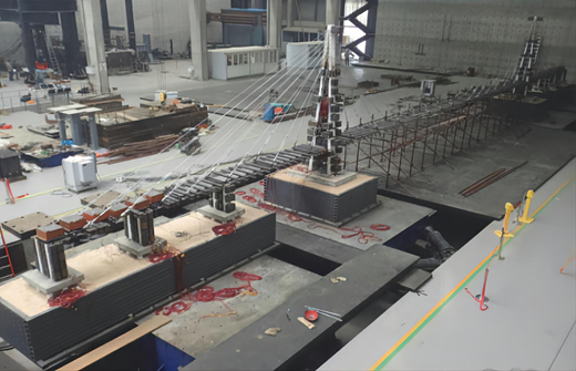
Yan et al. (2016a) designed a 1:40 full-bridge scaling model of Taizhou Yangtze River Highway Bridge and simulated the travelling wave effect, and the test results were basically consistent with the numerical calculation results. Xie and Sun (2018) conducted a scale model test on a super-long cable-stayed bridge with a main span of 1400 m with a similarity ratio of 1/70, and realized that the soil–structure interaction had a great influence on the dynamic characteristics of the bridge, and that the high-order vibration mode had the most obvious influence on the seismic response of the main tower. The test model of super-long span cable-stayed bridge is shown in Figure 8.
4.2 Application of the shaking table technology
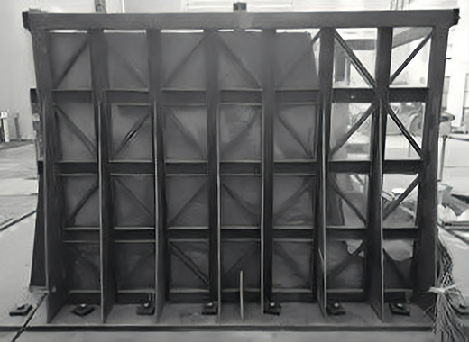
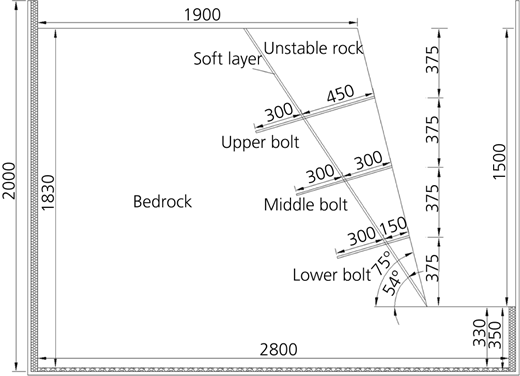
At present, the seismic simulation shaking table has been widely used in building structure engineering, bridge and tunnel engineering, geotechnical engineering, power transmission equipment engineering, atomic energy and weapons equipment research and other fields. Shi et al. (2018) and Han et al. (2018) applied a seismic simulation shaking table test technology to the structural vibration research of nuclear power plant equipment and liquid engine, and achieved ideal results. Ma et al. (2019) found out the main causes of dynamic soil pressure change under the earthquake action through the analysis of a series of soil slope reinforcement shaking table test, the results help people to better understand the characteristics of dynamic soil pressure, and provide a basis for strengthening the slope and improving the seismic stability of the structure. Li et al. (2020) explored the failure mode of large-span subway stations under asymmetric loads through the overall scale model test of subway stations. Pu et al. (2020) conducted a shaking table test on the dynamic response characteristics and failure mechanism of loess slope under earthquake action, and a method of S value is proposed to reflect soil failure and slope failure. Kavand et al. (2021) studied the influence of liquefaction on lateral expansion of pier wharf piles by combining large-scale shaking table test and numerical simulation under 1 g acceleration. The results show that the bending moment is larger when the pile side expands, and the bending moment of the down-slope pile is larger than that of the up-slope pile. Yan et al. (2020) used a seismic simulation shaking table to study and analyse the seismic response of anisotropic rock slope with a soft layer by a similar model test. The casting model and bolt arrangement are shown in Figures 9 and 10. In this experiment, the strain of two anchoring interfaces under seismic action was measured and the seismic response law between the anchoring rod and mortar of slope with inclined rock mass with soft layer, was studied.
With the acceleration of infrastructure construction in China, the seismic research on shaking table plays an increasingly prominent role in road and bridge engineering and electrical engineering. Chen et al. (2020) conducted three groups of large-scale simulation tests on the slope roadbed strengthened by bored piles on the Sichuan–Tibet Railway by using a shaking table. The results show that the bored piles could significantly improve the overall stability of the roadbed, and the seismic performance of double-row piles was better. Sun et al. (2019) conducted a seismic simulation shaking table test on the bridge–tunnel lap structure model of high-speed railway based on the similarity theory. The test simulation analysed the dynamic response and catastrophic behaviour of the bridge–tunnel lap structure under earthquake action with the condition of soft surrounding rock. The system composition of the bridge–tunnel lap shaking table model test platform is shown in Figure 11. Gong et al. (2020) conducted a 1:15 scale shaking table model test on the single-span 1000 kV outgoing frame under dynamic coupling action of transmission wires, and explored the influence mechanism of the dynamic coupling action of transmission wires on the seismic response of 1000 kV outgoing frame under longitudinal earthquake action.
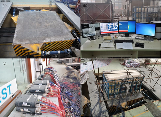
Shaking table model test platform system for the bridge–tunnel lapping: (a) shaking table, (b) operating deck, (c) test data acquisition instrument, and (d) model
Shaking table model test platform system for the bridge–tunnel lapping: (a) shaking table, (b) operating deck, (c) test data acquisition instrument, and (d) model
In recent years, the shaking table has also been applied in the field of cultural relic protection. Zhou et al. (2015) explored the influence of traditional reinforcement methods on the seismic performance of floating cultural relics through a 1:1 model seismic test. The research showed that the large difference between the fundamental frequency and the input seismic wave is one of the main reasons why the earthquake damage is not obvious for the display cases, and pointed out that the application of plastic clay and fishing line to reinforce cultural relics has a better effect on reducing the maximum value of the acceleration response of cultural relics. This study provides a new idea for the protection of cultural relics against earthquake. Ji et al. (2019) carried out a seismic simulation shaker scale model test with the outer brick wall of an ancient building as the object, and the results are clear: it provides a reliable basis for the repair, protection and seismic reinforcement of historic buildings.
5 Conclusions
In this paper, a comprehensive analysis and summary are made on the testing methods and technical applications of the construction situation and control technology of the shaking table, at home and internationally, and the following conclusions are drawn:
(i) The construction scale and type of seismic simulation shaking table have changed dramatically. At present, ‘electro-hydraulic servo-type three-directional 6 degrees of freedom large seismic simulation shaking table’ and ‘multi-combined shaking table vibration system’ have become the mainstream, and the construction of multi-functional shaking table has also become inevitable.
(ii) The control technology of seismic simulation shaking table system is quite mature, and the intelligent control algorithm and parameter tuning and compensation technology can effectively improve the control performance of the system. Neural network, self-learning intelligent algorithm and so on can provide more new ideas for the optimisation and development of shaking table control technology.
(iii) The relevant test methods of seismic simulation shaking table have been rapidly developed, which can provide seismic test technical support for many research fields. The application technology of seismic simulation shaking table can also be further developed towards the direction of ‘Internet +’ and ‘collaborative test of structural network’.
(iv) In future studies, researchers can try to predict the building damage in disaster areas before the earthquake through ‘Internet + shaking table’, which helps solve the challenge that the building environment in disaster-prone areas cannot be reasonably optimised and strengthened in advance before the earthquake.
Acknowledgements
This work is supported by the Graduate Research Innovation Fund of Xinyang Normal University, China (2020KYJJ49).

