
Reusing existing buildings is key in transitioning to a circular economy and meeting associated decarbonisation targets. Many adaptive reuse strategies, including vertical extensions, result in increased loads that need to be resisted by reserve structural capacity and/or strengthening. Previous work has identified structural under-utilisation within existing buildings and numerous sources of this have been suggested. However, understanding of associated contributions to reserve capacity and how this influences a building’s ability to be extended is limited. To address this, 11 scenarios, each modelling a different source of under-utilisation, were developed and applied in the design and reappraisal of 11 252 hypothetical steel-frame office buildings. An average reserve capacity of 10% was found in optimal Eurocode (EC) designs, rising to around 20% for British Standards and over 30% in the conservative or defensive application of ECs. Office to residential conversions were found to unlock an average reserve capacity of more than 20%. Across the 11 scenarios, 9–89% of considered cases were shown to be extendable without the need for strengthening. This demonstrates potentially significant extension potential within steel framed buildings, but that this varies with frame configuration, design/appraisal approach, and the extension’s use and structural material.
Notation
- b
bay width
- Cd
design value for serviceability criteria
- Ed
design value for the effect of actions on a member
- G
permanent load
- h
storey height
- n
number of storeys
- P
representative value of a prestressing action
- Q
imposed load
- Rd
design value for the resistance of a member
- αa
reduction factor for variable actions acting over large areas
- αn
reduction factor for variable actions acting over multiple storeys
- γG
partial factor for permanent actions
- γM
partial factor for material properties
- γP
partial factor for prestressing actions
- γQ
partial factor for variable actions
- ξ
reduction factor for permanent actions
- ψ
combination factor for variable actions
1. Introduction
Buildings are responsible for 34% of global energy consumption and 37% of associated greenhouse gas (GHG) emissions (United Nations Environment Programme, 2022). An increasing portion of this is in the form of embodied carbon (UK Green Building Council, 2021), resulting from the extraction and manufacture of materials and components; construction, maintenance and demolition of buildings; and processing and disposal of waste (RICS, 2017). A circular economy aims to reduce embodied GHG emissions by narrowing, slowing and closing resource flows, including through efficient design, lifespan extension and reuse and recycling (Bocken et al., 2016). In the built environment, strategies to achieve this include: the optimisation of structures and components; design for longevity, adaptability and deconstructability; the (adaptive) reuse of existing buildings; and the specification of reused/reusable components and recycled/recyclable materials (Astle et al., 2023; Gillott et al., 2023).
In the past, structural engineering practice and related research has typically focused on the narrowing of resource in-flows, through structural optimisation, and the closing of waste out-flows, through component reuse and recycling (Drewniok et al., 2020; Dunant et al., 2018). More recently, however, the benefits of slowing material flows through the reuse of entire buildings has come to the fore, leading to increasing research interest (Gosling et al., 2013; Rockow et al., 2021; Sundling, 2019) and both sectoral (AJ, 2019) and governmental (GLA, 2021) support.
Where a building’s reuse results in an increase in experienced loads (e.g. through change of use or vertical extension), these are required to be resisted by reserve capacity within the existing structure and/or its strengthening (Gillott et al., 2022a; Pattison, 2021). As suggested in studies considering reinforced concrete structures (Mei et al., 2024), identifying under-utilisation in case study buildings (Dunant et al., 2018; Moynihan and Allwood, 2014) and documenting known sources of over-design (Beal, 2011; Drewniok and Orr, 2018; Dunant et al., 2018; Gibbons, 1995; Gibson et al., 1995; Kala, 2007; Moynihan and Allwood, 2014; Orr, 2018; Orr and Drewniok, 2018; Orr et al., 2019), such reserve capacity is likely within at least some existing buildings (Gillott et al., 2022b).
1.1 Limit state design and structural utilisation
Limit state design, as employed in Eurocodes (ECs), ensures that the design value for the effect of actions on a member (Ed) does not exceed the corresponding design value for resistance (Rd) or relevant serviceability criteria (Cd). In the ECs (BSI, 2011), design values for action effects (Ed) are determined by applying a series of partial (e.g. γG and γQ), combination (e.g. ψ) and reduction (e.g. ξ) factors to characteristic actions (e.g. permanent loads (G) and imposed loads (Q)) based upon their likelihood of simultaneous occurrence. The conservative Equation 1 (equation 6.10 in BSI (2011)) is typically used here, with the alternative of the least favourable of Equation 2 (6.10a) and Equation 3 (6.10b) being less common in practice (BSI, 2011). Design values for member resistance (Rd) are calculated using characteristic material properties (e.g. yield strength) and an associated partial factor (γM) (BSI, 2005).
Calibration of partial, combination and reduction factors using ‘long experience of building tradition’ and ‘statistical evaluation of experimental data and field observations’ (British Standards Institution, 2011), results that designs in which Ed ≤ Rd and Ed ≤ Cd have a suitably low probability of failure and are thus deemed compliant. This relationship may alternatively be presented as Ed/Rd ≤ 1 or Ed/Cd ≤ 1, where Ed/Rd and Ed/Cd define member utilisation ratios (URs) for ultimate and serviceability limit states, respectively (Moynihan and Allwood, 2014).
1.2 Sources of reserve capacity in existing buildings
Mounting impetus for material efficiency has resulted in a number of studies considering both the extent and cause of under-utilisation within structural engineering design. These include the work of Moynihan and Allwood (2014) who, through the structural appraisal of 23 real-world steel-frame case studies, identified the average UR of 12 787 beams and 2347 columns to be just 0.40 and 0.49, respectively. Around 10% of this under-utilisation was suggested to result from the limited number of catalogue sections available for specification (Moynihan and Allwood, 2014), with the remainder being attributed to the rationalisation of designs to enhance simplicity and reduce costs (Gibbons, 1995; Gibson et al., 1995). A second study identifies an average mass-weighted UR of 0.65 across 30 case study buildings (Dunant et al., 2018), but observes no correlation between the level of design rationalisation and member underutilisations. Instead, as the distribution of URs exhibited a distinct peak around 0.8, the authors attributed the observed under-utilisation to the ‘defensive design practice’ of avoiding UR ≈ 1 (Dunant et al., 2018).
A subsequent industry survey, conducted as part of the MEICON (Minimising Energy in Construction) project, also suggested design rationalisation and the targeting of URs of 0.75–0.80 to be commonplace in structural engineering design (Orr, 2018; Orr et al., 2019). Additional work within the MEICON project considered disparities between imposed loads adopted in the design process, recommended in codes of practice and experienced by buildings in reality (Drewniok and Orr, 2018; Orr and Drewniok, 2018). The area-averaged imposed load used across the design of 95 buildings was found to be 4.63 kN/m2 (Orr and Drewniok, 2018), while the average value experienced across 13 prior studies was just 0.63 kN/m2 (Drewniok and Orr, 2018). Considering the recommend office loading of 2.5–4.2 kN/m2 in BS EN 1991-1-1:2002 (BSI, 2002), this represents a potential source of reserve capacity in buildings designed more conservatively than, or even in accordance with, current codes of practice. Reserve capacity may also be identified through a building’s reappraisal using loads associated with a less onerous use class, for example as part of an office to residential conversion.
Although partially accounting for decreased design uncertainty (e.g. in material and dimensional variation), the increasing efficiency of design codes over time (Beal, 2011) represents a potential additional source of reserve capacity. This includes the switch between permissible stress (e.g. BS 449-2:1969 (BSI, 1969)) and limit state approaches (e.g. BS 5950-1:2000 (BSI, 2001)), as well as the subsequent adoption of ECs (BSI, 2011). Perhaps the most obvious of these temporal disparities is in partial factors for permanent and imposed loads (γG and γQ, respectively), taken as 1.40 and 1.60 in BS 5950-1:2000 (BSI, 2001) and 1.35 and 1.50 in ECs (BSI, 2011). Additional optional factors for combinations of variable actions (ψ) and the reduction of permanent (ξ) and imposed loads acting over large areas (αa) or numbers of storeys (αn) are also offered by ECs (BSI, 2011). This represents the potential to identify reserve capacity even in buildings designed to current codes of practice, although the frequency of omission of such factors is unknown.
Reserve capacity may also be identified through the reappraisal of existing buildings using a modified EC approach. This includes reduction of the partial factor for permanent loads (γG) to 1.10 (shown to be permissible where the imposed load:total load = 0.15–0.55) (Kala, 2007) and the use of tested material strengths in place of characteristic values (Melcher et al., 2004; Orr, 2019).
1.3 Aims and objectives of this study
Despite the documentation of numerous sources of structural under-utilisation in existing studies, few have quantified the impact of these, and typically do so in terms of their compound effect in real-world structures (Dunant et al., 2018; Moynihan and Allwood, 2014). The majority of work is also concerned with enhancing material efficiency in the design of new buildings (e.g. through structural optimisation) (Drewniok et al., 2020; Dunant et al., 2018; Moynihan and Allwood, 2014), rather than utilising reserve capacity in existing buildings as part of their adaptive reuse. Partially as a result of this, focus is placed upon beam elements (Drewniok et al., 2020; Dunant et al., 2018; Moynihan and Allwood, 2014), further overlooking the potential for reserve column capacity as required for vertical extensions.
Where the influence of different under-utilisation sources on column capacity has been considered, this is only in terms of URs and potential load increases in reinforced concrete structures (Mei et al., 2024). Owing to their prevalence in the UK (British Constructional Steelwork Association, 2021), inherent suitability for adaptation (Astle et al., 2023) and experience of a majority of underutilisation sources (Section 1.2), this study focusses on braced, multi-storey, steel framed office buildings.
To address the above knowledge gaps and enhance understanding of structural under-utilisation, reserve capacity and vertical extension potential in existing buildings, this study
quantifies the impact of different known sources of under-utilisation in braced steel-frame columns
identifies associated reserve capacities in terms of permissible load increase and
contextualises the reserve capacities as potential for vertical extension in terms of the number of addable storeys.
2. Methodology
To assess the effect of individual sources of reserve capacity across a broad range of buildings, a suite of 11 under-utilisation scenarios (Section 2.1) was applied in the design and subsequent reappraisal of 11 252 hypothetical braced steel-frame office configurations (Section 2.2). For each of the 123 772 discrete combinations, the optimal (i.e. least mass) design was first generated using the relevant design approach, before being reassessed using the associated appraisal approach to calculate an adjusted design effect and/or resistance (Figure 1). Associated URs and reserve capacities were then calculated (Section 2.3) and finally contextualised as potential for vertical extension using typical per-storey loads (Section 2.4). For efficiency, the entire process was executed computationally in Matlab (MathWorks, 2021), with a sub-sample of frame configuration and under-utilisation scenario combinations being verified by traditional hand calculations.
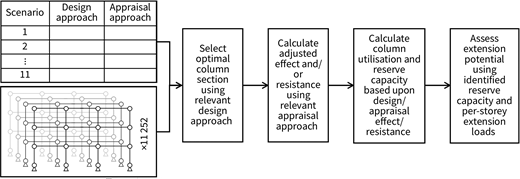
Developed methodological framework to assess utilisation, reserve capacity and extension potential within multi-storey framed buildings
Developed methodological framework to assess utilisation, reserve capacity and extension potential within multi-storey framed buildings
2.1 Under-utilisation scenarios
To represent the under-utilisation sources identified in Section 1.2, a set of 11 scenarios were developed (Table 1). These each comprise a design and appraisal approach, at least one of which follows optimal EC compliance in order to isolate consideration of a single utilisation source.
Developed under-utilisation scenarios and associated design and appraisal approaches
| Scenario | Design approach | Appraisal approach |
|---|---|---|
| 1 | BS 449-2:1969 (BSI, 1969): Optimal compliance | |
| 2 | BS 5950-1:2000 (BSI, 2001): Optimal compliance | |
| 3 | EC: Omitting reduction/combination factors (ξ, ψ) | |
| 4 | EC: Omitting imposed load reduction factors (αa, αn) | EC: Optimal compliance |
| 5 | EC: Targeting UR = 0.8 | |
| 6 | EC: Using over-specified imposed loads | |
| 7 | ||
| 8 | EC: Using experienced imposed loads | |
| 9 | EC: Optimal compliance | EC: Using residential imposed loads |
| 10 | EC: With average material strength | |
| 11 | EC: With reduced partial factor for permanent loads (γ) |
Scenarios 1–7 represent under-utilisation arising from buildings’ original over-design, namely
- ▪
the use of superseded design codes (scenarios 1 and 2)
- ▪
the application of current codes conservatively (scenarios 3 and 4) or defensively (scenario 5)
- ▪
the over-specifying of assumed loads (scenario 6)
- ▪
the use of catalogue sections (scenario 7).
Scenarios 8–11 represent under-utilisation unlocked through a building’s novel reappraisal, including
- ▪
using average-experienced imposed loads (scenario 8)
- ▪
as part of an office-residential conversion (scenario 9)
- ▪
using tested material strengths (scenario 10)
- ▪
using reduced partial factors (scenario 11).
Details of the parameters used in each design and appraisal approach are given in Tables 2 and 3, respectively.
Parameters employed in each design approach
| Design approach | Permanent floor load, Gk: kN/m2 | Imposed floor load, Qk: kN/m2a | Partial factor for permanent loads, γG | Partial factor for imposed loads, γQ | Permanent load reduction factor, ξ | Imposed load combination factor, ψ | Target UR | Material strength: MPa |
|---|---|---|---|---|---|---|---|---|
| BS 449-2:1969: Optimal compliance | 3.7–3.9b | 3.5d | 1.40f | 1.60f | — | — | N/Ac | 355h |
| BS 5950-1:2000: Optimal compliance | 3.7–3.9b | 3.5d | 1.40f | 1.60f | — | — | 1.0 | 355h |
| EC: Omitting reduction/combination factors (ξ, ψ) | 3.7–3.9b | 3.3e | 1.35g | 1.50g | — | — | 1.0 | 355h |
| EC: Omitting imposed load reduction factors (αa, αn) | 3.7–3.9b | 3.3e | 1.35g | 1.50g | 0.925g | 0.7g | 1.0 | 355h |
| EC: Targeting UR = 0.8 | 3.7–3.9b | 3.3e | 1.35g | 1.50g | 0.925g | 0.7g | 0.80 j,k | 355h |
| EC: Using over-specified imposed loads | 3.7–3.9b | 4.63i | 1.35g | 1.50g | 0.925g | 0.7g | 1.0 | 355h |
| EC: Optimal compliance | 3.7–3.9b | 3.3e | 1.35g | 1.50g | 0.925g | 0.7g | 1.0 | 355h |
Additional imposed load of 0.6 kN/m2 (BSI, 2008) is assumed to act at roof level
Comprising: steel self-weight (0.5 kN/m2 per storey below seven storeys, 0.7 kN/m2 per storey seven storeys and above) (SCI, 2008)
Target UR not applicable to the permissible stress approach employed in BS 449-2:1969 (BSI, 1969)
Comprising 2.5 kN/m2 plus 1.0 kN/m2 for moveable partitions (BSI, 1996)
Comprising 2.5 kN/m2 plus 0.8 kN/m2 for moveable partitions (BSI, 2002)
Parameters employed in each appraisal approach
| Appraisal approach | Permanent floor load: kN/m2 | Imposed floor load: kN/m2a | Partial factor for permanent loads | Partial factor for imposed loads | Permanent load reduction factor | Imposed load combination factor | Target UR | Material strength: MPa |
|---|---|---|---|---|---|---|---|---|
| EC: Optimal compliance | 3.7–3.9b | 3.3d | 1.35 | 1.50e | 0.925e | 0.7e | 1.0 | 355f |
| EC: Using experienced imposed loads | 3.7–3.9b | 0.63g | 1.35e | 1.50e | 0.925e | 0.7e | 1.0 | 355f |
| EC: Using residential imposed loads | 3.7–3.9b | 2.0d | 1.35e | 1.50e | 0.925e | 0.7e | 1.0 | 355f |
| EC: With average material strength | 3.7–3.9b | 3.3d | 1.35e | 1.50e | 0.925e | 0.7e | 1.0 | 402i |
| EC: With reduced partial factor for permanent loads (γ) | 3.7–3.9b | 3.3d | 1.10h | 1.50e | — c | — c | 1.0 | 355f |
Additional imposed load of 0.6 kN/m2 (BSI, 2008) is assumed to act at roof level
Comprising: steel self-weight (0.5 kN/m2 per storey below seven storeys, 0.7 kN/m2 per storey seven storeys and above) (SCI, 2008)
No load reduction/combination factors applied due to their omission when deriving reduced partial factors (Kala, 2007)
Comprising 2.5 kN/m2 plus 0.8 kN/m2 for moveable partitions (BSI, 2002)
2.2 Hypothetical frame configurations
The 11 252 considered office configurations were obtained from a parameterised, simply constructed, steel-frame of varying storey height (h), bay width (b) and number of storeys (n) (Figure 2). A bisymmetric structural grid was assumed, eliminating the need to consider nominal end moments, dictating that minor axis member buckling capacity was critical in all instances and resulting in a one-dimensional problem. Lateral and seismic forces were not considered, assuming sufficient capacity within, or localised strengthening/replacement of, roof-level structures, lateral bracing systems, splices, baseplates and foundations.
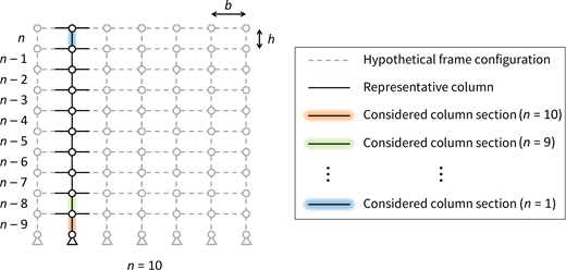
Indicative simply constructed, braced steel frame of storey height (h), bay width (b) and storey number (n)
Indicative simply constructed, braced steel frame of storey height (h), bay width (b) and storey number (n)
To model a pragmatic yet broad range of likely real-world cases, frame parameters were varied uniformly between upper and lower limits typical across the UK building stock. Storey heights were taken as 2–8 m (in 0.25 m increments), bay widths as 4–15 m (in 0.25 m increments) and number of storeys as 1–10. A consistent bay width within each configuration meant that all the internal columns were identical and could be modelled by a single representative member (Figure 2). As shown in Figure 2, only the ground floor portion of this was required to be explicitly analysed for each configuration, with the upper floors being considered implicitly when assessing configurations with fewer storeys.
2.3 Utilisation and reserve capacity
Although following the general workflow in Figure 1 and detailed below, column utilisations and reserve capacities were calculated using alternate processes for scenarios comprising non-standard design (scenarios 1–6) and appraisal (scenarios 8–11) approaches (Figure 3). This is because of the need to repeat the design of each frame configuration for scenarios employing a non-standard design approach (scenarios 1–6), but not when designing to optimal EC compliance (scenarios 7–11). In all cases, and throughout both the initial design and reappraisal process, column effective lengths were taken as equal to the storey height.
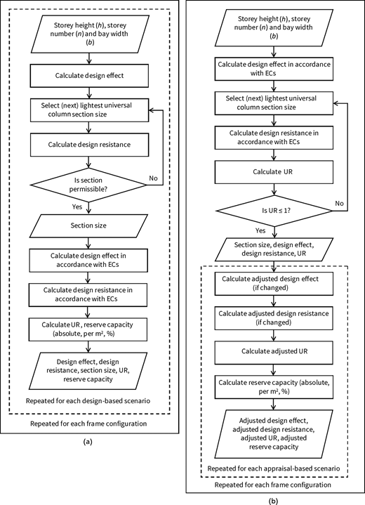
Detailed assessment workflows for under-utilisation scenarios employing: (a) non-standard design approaches (scenarios 1–6); (b) standard design approaches (scenarios 7–11)
Detailed assessment workflows for under-utilisation scenarios employing: (a) non-standard design approaches (scenarios 1–6); (b) standard design approaches (scenarios 7–11)
As shown in Figure 3, for each of the 123 772 discreet under-utilisation scenario and frame configuration combinations, the axial load within the representative column was first calculated in accordance with the relevant design approach (Table 1). The column was initially assumed to be of the lightest catalogue universal column section in published design data (SCI et al., 2015) and its minor-axis buckling resistance calculated using the relevant design approach (Table 1). Next, ultimate limit state design compliance was checked using an associated UR (Section 1.1), except in scenario 1 (representing design to BS 449-2:1969 (BSI, 1969)) where the permissible stress approach was used. If this section size did not satisfy the buckling resistance requirements of the current frame configuration and design approach combination (i.e. UR > 1), the next lightest section was selected, the resistance recalculated and the compliance check repeated. This iterative process was continued until the optimal (i.e. lightest yet permissible) section was identified.
Next, assuming it was of this optimal section size, the representative column was reassessed in accordance with the relevant appraisal approach (Table 1) to calculate an adjusted design effect and/or resistance. Using the appropriate combination of the original and adjusted design effect and resistance (Table 1) a second UR was calculated, indicating the utilisation of the representative column under the current scenario. Associated reserve capacity was also calculated in absolute (kN) and area-averaged (kN/m2) terms, as well as a percentage of the column’s original EC design effect.
2.4 Potential for vertical extension
To contextualise the identified reserve capacities in terms of resultant extension potential, a set of four typologies was considered. These represent hypothetical extensions designed for office or residential use, employing a traditional hot-rolled steel frame (i.e. matching the existing building) or a lightweight cold-formed alternative.
Permanent loads for hot-rolled steel extensions were taken as 3.7 kN/m2 (as in Tables 2 and 3), while the lightweight alternative assumed values of 1 kN/m2 for cold-formed steel framing (including flooring) (Lawson et al., 2004) and 0.25 kN/m2 for accompanying services (SCI, 2008). Similarly, whereas imposed loads due to moveable partitions remained at 0.8 kN/m2 per storey for the hot-rolled framing case, a reduced value of 0.5 kN/m2 (BSI, 2002) was used in the lightweight alternative. Additional imposed loads were assigned according to the hypothetical extension’s assumed use, with values of 2.5 kN/m2 and 1.5 kN/m2 being adopted for office and residential, respectively (BSI, 2002).
Combination (ψ) and reduction factors (ξ, αa and αn) were omitted when calculating design actions for the four extension typologies, resulting in a single per-storey load for each. Extension potential was thus calculated simply by dividing the reserve capacities by these values.
3. Results and discussion
3.1 Utilisation
Across the 123 772 considered frame configuration and under-utilisation scenario combinations, the URs varied in the range 0.11–1.00. Minimum URs for each scenario varied between just 0.11 (scenarios 10 and 11) and 0.12 (scenarios 1–9), with maximum URs ranging between 0.80 (scenario 5) and 1.00 (scenario 7). Consistently low minimum URs across each scenario resulted from the consideration of a small number of particularly non-onerous and unlikely frame configurations (i.e. combinations of low bay width, storey height and storey numbers), for which even the lightest sections were significantly under capacity. Similarly, maximum URs for each scenario represent those for just a small number of particularly favourable frame configuration and design load combinations. To mitigate the influence of these extreme UR values, upper and lower bounds (indicated by whiskers in Figure 4) were defined at 1.5 times the interquartile range from the median.
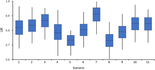
Distribution of URs for the 11 252 frame configurations considered under each of the 11 under-utilisation scenarios (see Table 1). To mitigate the effect of a small number of unlikely extreme values, whiskers indicate upper and lower bounds 1.5 times the interquartile range from the median
Distribution of URs for the 11 252 frame configurations considered under each of the 11 under-utilisation scenarios (see Table 1). To mitigate the effect of a small number of unlikely extreme values, whiskers indicate upper and lower bounds 1.5 times the interquartile range from the median
Figure 4 shows the median UR for columns designed and appraised to optimal EC compliance (scenario 7) to be just 0.91. This is in general agreement with the previously reported value of 0.90 (Moynihan and Allwood, 2014), suggesting the use of catalogue sections to introduce an average of ∼10% under-utilisation where columns are otherwise optimally designed using current codes of practice. Quartile values of 0.81 and 0.96 indicate at least some under-utilisation in the majority of cases, varying between ∼5% and ∼20% for more or less favourable configurations.
Median utilisation in columns designed using superseded codes was lower than for compliance with ECs, with URs of 0.82 and 0.84 obtained for BS 449-2:1969 (BSI, 1969) (scenario 1) and BS 5950-1:2000 (BSI, 2001) (scenario 2), respectively (Figure 4). This is indicative of increases in efficiency between successive British Standards and ECs (Beal, 2011), resulting from the switch between permissible stress (BSI, 1969) and limit state (BSI, 2001), the reduction of permanent and imposed load factors (BSI, 2011) and the introduction of additional factors for the reduction and combination of loads (ξ, ψ, αa, αn) (BSI, 2011).
EC designs omitting permanent load reduction (ξ) and variable action combination (ψ) factors (scenario 3) (i.e. using Equation 1) resulted in a median UR of 0.87. The associated value when omitting reduction factors for imposed loads acting over large areas (αa) and multiple storeys (αn) (scenario 4) was just 0.78. This shows how the conservative application of ECs can result in greater under-utilisation than the use of superseded codes in some cases. The same is true for the defensive application of ECs, with the targeting of UR = 0.8 (Dunant et al., 2018; Orr, 2018; Orr et al., 2019) (scenario 5) giving a median value of just 0.73.
When reappraised using the recommended value of 3.3 kN/m2 in the EC (BS EN 1991-1-1:2002 (BSI, 2002)), designs generated assuming imposed loads of 4.63 kN/m2 (Orr and Drewniok, 2018) (scenario 6) were found to have a median UR of 0.81. Further under-utilisation was found when optimal EC designs were reappraised using average-experienced imposed loads (0.63 kN/m2 (Drewniok and Orr, 2018)) (scenario 8) or those recommended for residential use (2.0 kN/m2 (BSI, 2002)) (scenario 9), giving median URs of 0.73 and 0.79, respectively. This reiterates the often-significant contribution of design conservativity to under-utilisation within existing buildings and suggests the opportunity to identify further under-utilisation through reappraisal using modified design values. Such a possibility is also posed by scenarios 10 and 11, which both resulted in median URs of 0.85.
3.2 Reserve capacity
For ease of comparison, Figure 5 shows the reserve capacities for the 123 772 considered frame configuration and under-utilisation scenario combinations as a percentage of the original optimal EC design effect. Whiskers again represent upper and lower bounds at 1.5 times the interquartile range from the median, in order to mitigate the influence of a small number of particularly non-onerous and favourable frame configurations.
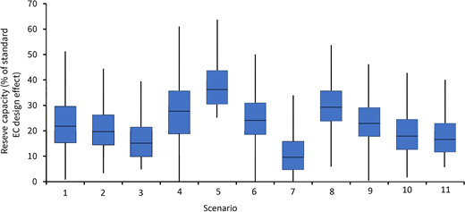
Distribution of reserve capacities for the 11 252 frame configurations considered under each of the 11 under-utilisation scenarios (see Table 1). To mitigate the effect of a small number of unlikely extreme values, whiskers indicate upper and lower bounds 1.5 times the interquartile range from the median
Distribution of reserve capacities for the 11 252 frame configurations considered under each of the 11 under-utilisation scenarios (see Table 1). To mitigate the effect of a small number of unlikely extreme values, whiskers indicate upper and lower bounds 1.5 times the interquartile range from the median
Figure 5 reveals an average of 10% reserve capacity in buildings designed to optimal EC compliance (scenario 7). Although matching the rule of thumb reportedly used in practice (Gillott et al., 2022b), upper and lower bounds of 0% and 33% suggest this to be either unsafe or conservative in some cases. On average, more than double the reserve capacity was identified in buildings designed to superseded codes of practice, with median values of 22% and 20% being obtained for BS 449-2:1969 (BSI, 1969) (scenario 1) and BS 5950-1:2000 (BSI, 2001) (scenario 2), respectively. Alongside quartile values of 15–30% and 14–26%, this suggests the possibility of adopting an increased rule of thumb value for buildings designed to British Standards.
EC designs omitting permanent load reduction (ξ) and variable action combination (ψ) factors (scenario 3) were found to have a median reserve capacity of 15%. The corresponding value for the omission of factors for imposed loads acting over large areas (αa) and multiple storeys (αn) (scenario 4) was almost twice this (28%), revealing reserve capacity in EC-designed columns to vary greatly depending upon how conservatively these are applied. Associated bounds of 3–39% (scenario 3) and 0–61% (scenario 4) indicate similar disparity across different frame configurations, with the greater range for scenario 4 resulting from the variation of αa and αn factors with bay width (b) and storey number (n) (Beal, 2011). Because of the unknown frequency with which different reduction and combination factors have been omitted over time, the prevalence of associated reserve capacity within the building stock is unclear.
As suggested in previous works (Dunant et al., 2018; Orr, 2018; Orr et al., 2019), the defensive targeting of UR = 0.8 (scenario 5) is perhaps more common, and was found to result in a median reserve capacity of 36%. This suggests reserve column capacities of ∼1/3 to be widespread across the existing building stock, with potential for this to increase through omission reduction and/or combination factors on a case-by-case basis. As is also common within office building design (Orr and Drewniok, 2018), the over-specification of imposed loads was found to result in a median reserve capacity of 24% when reappraised to optimal EC compliance (scenario 6).
Even in buildings designed assuming EC-recommended loads, additional reserve capacity may be identified through reappraisal using average-experienced values (Drewniok and Orr, 2018) or those for alternate uses. This resulted in median reserve capacities of 29% (scenario 8) and 23% (scenario 9), with the latter value for appraisal using residential loads indicating scope to unlock significant reserve capacity as part of a building’s change of use. In real-world cases, the effect of a building’s original design using over-specified imposed loads may be compounded by that of its reappraisal using those experienced in reality or representing a less onerous use. This introduces potential for greater amounts of reserve capacity than suggested in Figure 5 within portions of the UK building stock.
Reappraisal using tested material strengths (Melcher et al., 2004) (scenario 10) and modified design codes (Kala, 2007) (scenario 11), resulted in median reserve capacities of 18% and 17%, respectively (Figure 5). Although potentially requiring a more involved on-site investigation and design reappraisal process, this represents the potential to identify small amounts of additional reserve capacity in specific members to supplement that from other sources.
3.3 Extension potential
Figure 6 shows the proportion of the 11 252 considered frame configurations to which different numbers of storeys may be added under the 11 considered scenarios. The figure shows possible extensions of both office and residential use, employing a standard hot-rolled steel frame (S) or a lightweight cold-formed steel alternative (L). Across all scenarios and extension typologies, 9–89% of the considered frame configurations may be extended without strengthening. Residential extensions and/or those using a lightweight frame were found to have the greatest potential for extension as a result of their lower associated loads.
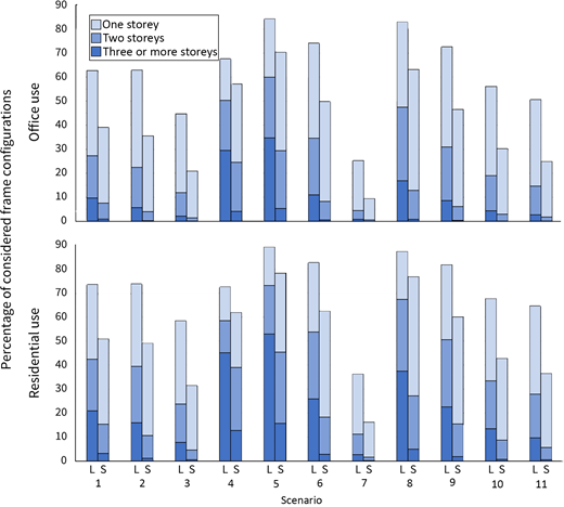
Percentage of considered frame configurations within each under-utilisation scenario (see Table 1) extendible by different numbers of storeys when using a lightweight (L) or standard (S) steel frame for office or residential use
Percentage of considered frame configurations within each under-utilisation scenario (see Table 1) extendible by different numbers of storeys when using a lightweight (L) or standard (S) steel frame for office or residential use
Depending upon the extension’s use and structural material, between 9% (standard office) and 36% (lightweight residential) of optimal EC-designed configurations (scenario 7) were found to be extendible by at least one storey. This indicates the use of catalogue sections to frequently facilitate extensions without the need for strengthening, even in buildings that have been designed efficiently using current codes of practice.
For superseded design codes the potential for extension increased to 36–74%, representing buildings designed to BS 5950-1:2000 (BSI, 2001) (scenario 2) employing a standard office extension and buildings designed to BS 449-2:1969 (BSI, 1969) (scenario 1) employing a lightweight residential extension. As well as a greater number, the buildings designed to British Standards could also typically be extended by a greater degree. This is exemplified by the possibility of adding three or more storeys in up to 21% of configurations designed to BS 449-2:1969 (BSI, 1969) (scenario 1) without the need for strengthening.
In the EC designs, the omission of permanent load reduction (ξ) and variable action combination (ψ) factors (scenario 3) or reduction factors for imposed loads acting over large areas (αa) and multiple storeys (αn) (scenario 4) facilitated extension in 21–74% of cases (Figure 6). This suggests that, in reality, a greater number of EC-designed buildings than indicated by scenario 7 (9–36%) may be extended. However, the prevalence of this increased potential within the building stock is unclear because of the unknown frequency with which different factors have been omitted over time.
In contrast, the defensive targeting of UR = 0.8 (scenario 5) is thought to be commonplace (Dunant et al., 2018; Orr, 2018; Orr et al., 2019), and was found to facilitate extension without strengthening in 70–89% of cases (Figure 6). The over-specification of imposed loads in office buildings (scenario 6) is known to be a similarly common practice (Orr and Drewniok, 2018), with 50–74% of associated cases being extendible without the need for strengthening. Together, these values suggest an enhanced potential for extension to be likely within a large number of existing buildings (Dunant et al., 2018; Orr, 2018; Orr and Drewniok, 2018; Orr et al., 2019).
Reappraisal using reduced imposed loads (scenarios 8 and 9) also revealed an increased potential for extension, with 47–87% of the cases considered being extendible by at least one storey. Particularly pertinent here is reappraisal using residential imposed loads (scenario 9), for which 60% and 82% of cases may be extended when assuming residential extensions employing standard and lightweight framing, respectively. This represents the extension potential unlocked through office to residential conversion, indicating the majority of steel-frame office buildings to be extendible without strengthening as part of this hybrid reuse approach. Multiple storeys are also likely to be addable, with a lightweight steel frame enabling extension by three or more storeys in 23% of cases (Figure 6).
3.4 Limitations and future work
This study considered only vertical load transfer through columns in braced, steel-frame offices, assuming sufficient capacity within, or localised strengthening/replacement of, roof-level structures, lateral bracing systems, splices, baseplates and foundations. Fatigue, corrosion and aging were also neglected, with structural degradation and the assessment of reserve capacity within additional elements thus being recommended as part of future work. A broader understanding of reserve capacity and extension potential across different building types could also be obtained through future consideration of moment (i.e. unbraced) frames and those with non-bisymmetric grids, as well as buildings of different use and structural material.
As discussed in Section 2.1, in order to better understand their relative contribution to reserve capacity, each of the 11 scenarios was developed such that they modelled a single under-utilisation source. In reality, these are not mutually exclusive, suggesting greater representation of real-world structures to potentially be obtained by future assessment of likely combined scenarios. To better understand applicability to real-world structures, additional work mapping the considered scenarios to the UK’s existing building stock is also recommended. In the case of superseded design codes (scenarios 1 and 2) and adjusted imposed loads (scenarios 6, 8 and 9) this may be achieved based upon a building’s age and/or use. For scenarios pertaining to conservative (scenarios 3 and 4) or defensive (scenario 5) practices, however, this would require the collection of additional data to understand their relative prevalence in buildings of different use, age and material.
4. Conclusion
Following growing impetus for adaptive reuse (AJ, 2019; GLA, 2021; Gosling et al., 2013; Rockow et al., 2021; Sundling, 2019) and the associated potential for increased loads, this study assessed the impact of different known sources of under-utilisation on reserve capacity and vertical extension potential in steel-frame columns. In doing so, 11 under-utilisation scenarios were developed and applied in the design and reappraisal of 11 252 hypothetical frame configurations, totalling 123 772 combinations overall. The identified reserve capacities were contextualised in terms of associated potential for extension, assuming both office and residential use and hot-rolled and lightweight steel framing.
Consistent with industry rules of thumb (Gillott et al., 2022b), a median reserve capacity of 10% was identified in buildings designed to optimal EC compliance. This suggests extension without strengthening to be possible in 9–36% of cases, indicating the ability to extend buildings that have been designed efficiently using current codes of practice. Buildings designed to British Standards were found to have an increased median reserve capacity of around 20%, enabling extension in up to 74% of cases and suggesting the possibility of adopting enhanced rules of thumb for buildings from different periods.
Employing ECs in a conservative or defensive manner (i.e. sub-optimally) increased the median reserve capacity to 15–36%. Although known to be prevalent (Dunant et al., 2018; Orr, 2018; Orr et al., 2019), the proportion of existing buildings to which different conservative and/or defensive approaches apply is not currently understood. This necessitates collection of further practice-based data to identify the proportion of the existing building stock in which different reserve capacities are likely to be present.
Reappraising a building using reduced imposed loads (e.g. for a less onerous use) revealed median reserve capacities of 23–29%. This represents the ability to extend without strengthening in 60–82% of office to residential conversions, depending upon the grade of structural steel used. Such large potential is particularly pertinent in the UK, considering the existence of office to residential permitted development rights (HMG, 2021) and the growing housing demand.
Overall, this work reveals sufficient reserve capacity to facilitate extension in a broad range of scenarios, including where a building has been designed efficiently using ECs. Increased reserve capacity and extension potential was identified in buildings designed using superseded codes of practice or when ECs were applied in a conservative or defensive manner. This is similarly true when reappraising buildings using adjusted design values, with a significant extension potential being unlocked through a building’s conversion from office to residential use.
As well as the modelled scenarios, reserve capacity and extension potential were found to vary greatly across the frame configurations and extension typologies considered. This variability is consistent with previous work (Gillott et al., 2022b; Pattison, 2021) but does not preclude the adoption of a suite of enhanced rules of thumb value for different buildings archetypes. These may be assigned using a building’s age, use and/or additional practice-based data, and should be mapped onto the UK’s building stock as part of future work.
Acknowledgement
This project was funded by EPSRC under the studentship project number 2280211.
