
The adaptive reuse of 76 Southbank, London, formerly the IBM building, presents a compelling case study in overcoming the challenges of refurbishing iconic structures to meet modern sustainability, economic and social demands. Faced with the need to retain much of the original structure, the project team implemented innovative methods in materials science and engineering, including the reuse of structural elements, to reduce the building’s carbon dioxide footprint while meeting conservation standards. This paper shares key lessons from the project, demonstrating how materials science can alleviate uncertainty for building owners and insurers. By rigorously assessing the in situ strength of retained materials and using advanced techniques like reused steel and foundation adaptation, the project sets a new benchmark for sustainable refurbishment. The authors suggest that these methods can lower the barriers to adaptive reuse, effectively enabling more projects of this kind. In doing so, this approach responds to pressing economic and social drivers, such as high sustainability demands, rising costs and the need for functional, environmentally responsible spaces. By adopting these strategies, insurers and engineers can better support building owners, unlocking the potential for more sustainable urban renewal.
1. Introduction
The current economic and environmental landscape is defined by high base rates, post-Covid shifts in working culture, stringent planning requirements and the impending introduction of more rigorous life cycle assessment and energy performance certification legislation, placing paramount emphasis on sustainability. Refurbishing existing buildings has become both an economic imperative and a sustainability priority. Asset owners face the risk of their properties becoming ‘stranded assets’ if they fail to meet contemporary utility, sustainability and heritage conservation standards. Concurrently, there is growing tenant demand for sustainable, functional spaces to attract workers back to the office, reflecting broader societal shifts towards environmental responsibility and resilience.
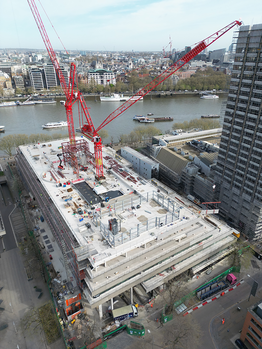
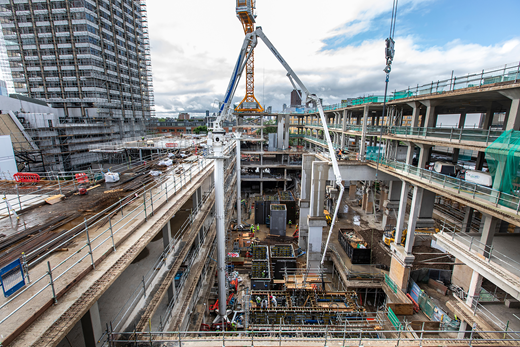
The 76 Southbank project, involving the adaptation and reuse of the iconic former IBM building on London’s Southbank (Figure 1), serves as a landmark case study. Local planners rejected initial proposals that involved extensive demolition of the structure. Furthermore, during the process of securing planning permission for a larger building with more floor space, the building received a Grade II listing. This affirmation required the design response to deliver a shorter programme with lower associated risks, necessitating a complete re-evaluation of the design approach. As a result, the project team focused on maximising reuse of the building to ensure the scheme remained commercially viable while adhering to conservation guidelines.
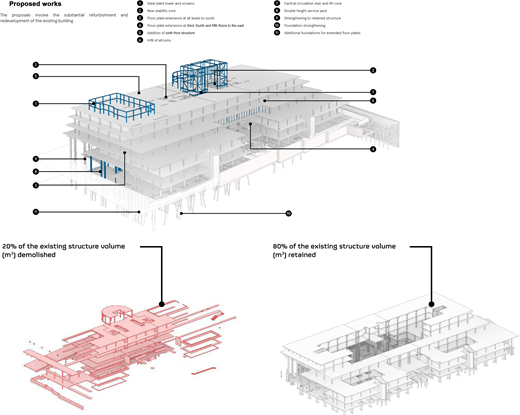
The project achieved an approximately 40% increase in the usable area by employing innovative solutions to justify 30% load increases on superstructure and foundation elements (and therefore reuse) and retained 80% of the existing building fabric. This was achieved with support from materials science and the introduction of reused steel sections – distinct from recycling – underscoring the team’s dedication to reducing the carbon dioxide footprint of the reimagined building.
This paper delves into the methodologies and rationale behind these principles, detailing the technical hurdles overcome and the collaborative efforts required to modernise a historic structure while aligning with statutory conservation requirements (Planning (Listed Buildings and Conservation Areas) Act 1990) and the guidance provided by Historic England (HE, 2008, 2018).
By sharing learning and experiences, the aim of this paper is to provide valuable insights into the engineering community and stakeholders involved in similar adaptive reuse projects. The authors also suggest that engineers advising the insurance industry could benefit from adopting extended materials science approaches to enable more of these adaptive reuse projects.
2. Assessment of the existing structure to maximise retention and minimise demolition
The existing Grade II listed building at 76 Southbank was originally constructed between 1980 and 1983. It consists of a five-storey reinforced concrete frame with a part single-level basement, occupying a plan area of approximately 67 m × 157 m.
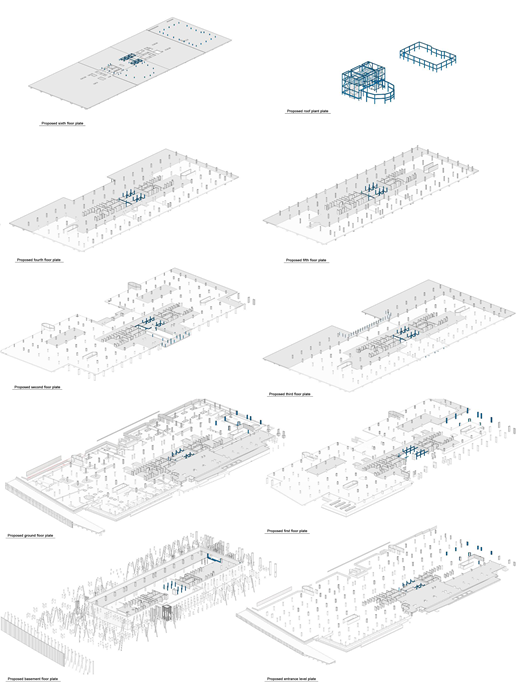
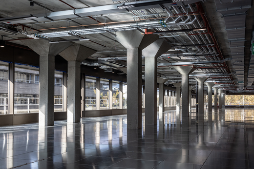
The proposed refurbishment aimed to add an additional storey and extend the existing floor plates (Figure 2), increasing the usable area by approximately 40%. A core objective of the project was to retain and reuse as much of the original structure as possible, driven by both sustainability goals and the heritage status of the building (Figure 3).
Heyne Tillett Steel (HTS), as the structural engineer appointed before other consultants, conducted a thorough search of available archive information. A full set of structural record drawings was obtained from Arup’s archives, providing essential details of the building’s original design, including framing, load paths and material capacities. This data was used to create a comprehensive digital twin of the building.
Concrete flat slabs typically spanned onto concrete columns on a 7.2 m by 7.2 m grid. The columns had flared capitals to increase the slab punching shear perimeter. Columns were typically continuous from roof level to foundation level. Some columns were supported on downstand transfer beams where the building mass stepped back at upper storeys and to create column-free entrance spaces.
This initial research was then provided as part of the tender documents for other design consultants so that the building’s retrofit schemes could be designed from the concept stage to work efficiently and sensitively with the existing structure. In this way, a scheme was developed that maximised the retention and – more importantly – reuse of the existing structure, which became an increasingly crucial factor once the building was listed.
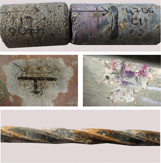
During the early design stages, structural assessments were initially based on archive data, particularly the specified element sizes, reinforcement details and material strengths. However, the risk that the building may not have been constructed as designed and the inherent variability in the strength of concrete posed significant concerns, especially given that 80% of the structure was to be retained (Figure 4) and subjected to new loading conditions (and combination cases to the Eurocodes).
To reduce this risk during the design period, HTS analysed a set of archive concrete cube test results taken from the construction phase of the original frame to estimate the characteristic in situ compressive strength of the concrete in the structure at 28 days following the statistical method described in BS EN 13791:2007 (BSI, 2007). The characteristic strength estimated using this method showed a high correlation with the specified strength. For example, for an archive-specified concrete grade for columns of 40 N/mm2, the estimated in situ strength from the cube tests was 42.5 N/mm2.
Once the building was vacated, HTS conducted a detailed programme of intrusive investigations to verify the archived drawings and validate the design assumptions. This involved measuring element dimensions, examining reinforcement arrangements and extracting concrete cores for testing. The results showed that the building was generally constructed as per the original design, with some variations in concrete strength. Notably, many core samples revealed a concrete strength higher than specified, particularly in the columns, where certain cores exceeded the expected characteristic strength, offering opportunities to minimise the need for strengthening.
This observation of over-strength concrete was used to reassess the requirement to strengthen certain concrete elements. In the pre-investigation design, the capacity of all retained existing columns was checked against the design loads expected from the development of the building using the archive-specified strength. This assessment resulted in 160 columns being over-utilised in the proposed condition by up to 60%. For these, a strengthening detail providing a 75 mm reinforced concrete jacket around the existing column was developed.
Location-specific core investigations were carried out on columns identified as potentially over-utilised in the proposed condition. The aim was to determine if the in-situ concrete strengths exceeded the values stated in archival records sufficiently to increase column capacities above the anticipated design loads, thereby eliminating the need for jacket strengthening.
The investigations proceeded systematically, starting with columns exhibiting lower levels of over-utilisation and gradually progressing to those with higher demands, until further justification for omitting jackets was no longer achievable. In total, 98 columns underwent strength testing. Of these, 26 columns (representing 16% of the total assessed) demonstrated sufficient in-situ strength to eliminate the requirement for jacket strengthening. The highest level of over-utilisation addressed successfully through this testing strategy was 30% above the original archive design capacity.
While the testing of 98 columns incurred initial costs, the resultant savings from avoiding jacket strengthening on 26 columns substantially outweighed this expenditure, clearly demonstrating a cost-effective approach. Additionally, the omission of these 26 jackets resulted in a further environmental benefit, saving an estimated 6–8 tonnes of embodied carbon dioxide emissions.
3. Foundation and D-wall reuse and strengthening (Patel et al., 2024)
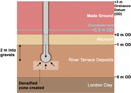
The 76 Southbank building is founded, unusually, on reclaimed land from the River Thames in the north and natural low-lying ground, just above the maximum high tide level. The foundations are very unusual as the main structure is supported by groups of driven cast-in-situ Franki piles (Figure 5), each with a diameter of 500 mm and an enlarged bulb created by the driving of a concrete plug, found in Terrace Gravels at a shallow depth of 5–6 m. However, quantifying the exact size of these enlarged bulbs was difficult, which posed challenges when considering the reuse of these piles to support the increased loads from the additional floors and infilled atriums.
There were almost 460 existing Franki piles, each carrying nearly 1 MN (100 t), which today would be considered a very efficient and sustainable piling system. Franki piles are no longer in use, making the evaluation of their reuse a complex task due to several factors.
- ▪
Group pile effects. The contractor (Frankipile Ltd) carried out pile load testing in 1980 at the 76 Southbank site and showed that driving piles in close proximity caused uplift of adjacent piles, resulting in a softer overall response in the pile group compared with individual piles (Frankipile Ltd, 1980).
- ▪
Dependency on workmanship. The capacity of Franki piles is significantly influenced by the end-bearing on the densified gravels created by the driving of the concrete plug while installing the pile, making the system highly dependent on workmanship quality.
- ▪
Groundwater table changes. Any rise in the groundwater table over the past 40 years could reduce the effective stress on the pile bulbs, thereby decreasing their load-bearing capacity.
- ▪
Impact of new works. Temporary dewatering or surcharge surface loading from new construction activities could induce downdrag forces in the soft alluvial clays, which would overload the piles and risk damage to the structure.
- ▪
Excavations. Much of the pile end-bearing capacity is based on the overburden pressures above the Franki bulb. Excavating for new works (lift pits, deep service shafts) would reduce the pile capacity, which would have equally damaging consequences for the structure.
Considering the given constraints, the structural and geotechnical engineers encountered significant challenges when devising a foundation reuse strategy for the redevelopment of a building constructed 40 years ago.
3.1 Use of 1980s archives and risk mitigation
Reuse of the Franki piles carried significant risk as they were designed to carry heavy loads on a small-diameter base. To ensure the feasibility of the foundation reuse strategy, Arup relied heavily on the original geotechnical reports, pile load test data and as-built records from the 1980s. As the original designers, Arup was ideally placed to lead the geotechnical effort.
The foundation reuse strategy followed the best practice guidance (Ciria, 2007), modified to reflect Arup’s more recent experience. The first step involved conducting due diligence and gap analysis on the existing foundation information. This process was critical to understanding the length and diameter of the Franki piles, their concrete grade, load test performance and pile cap group arrangements. Although the as-built information from the original contractor was incomplete, the team began forming a risk profile for the reuse scheme.
3.2 Ground investigations and testing
To determine whether the Franki piles could support the new loads, Arup Geotechnics, in collaboration with HTS, Keltbray and Keller Ground Engineering, undertook a comprehensive foundation revalidation process. This included revalidation pile testing, site drilling trials and instrumented boreholes, all conducted while the building remained occupied. The testing revealed that the team could reuse up to 95% of all the original Franki piles, which, once retested after 40 years were validated for 30% additional load compared with the original designer’s intent in 1980. This enabled the floor area of the existing building to be increased by almost 40% using the existing piles.
Without an integrated geotechnical and structural approach, the project would not have been commercially viable. Thanks to the robust foundation reuse strategy for the highly unique Franki piles developed by the design team, insurers were provided with a clear, de-risked plan. This included extensive design documentation, site testing, construction controls and ground movement monitoring data.
The ground investigation strategy included boreholes, cone penetration tests (CPTs), and groundwater monitoring carried out by contractors RSK in 2022. The Franki piles pass through 4 m of Made Ground and Alluvium and are embedded approximately 2 m into water-bearing Terrace Gravels, which extend down to London Clay. The unique Franki pile installation method of driving a concrete plug to create a densified gravel zone was investigated further on site by comparing CPTs (Figure 6) in natural gravels and CPTs through the densified gravel adjacent to existing driven piles. These tests, along with dummy pile tests, provided invaluable data for evaluating the potential of foundation reuse.
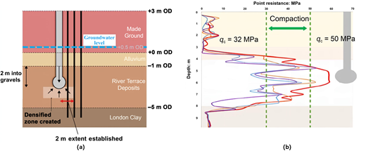
Ground investigation and CPTs: (a) CPTs carried out after pile installation; (b) CPT results showing 60% improvement in densified zone
Ground investigation and CPTs: (a) CPTs carried out after pile installation; (b) CPT results showing 60% improvement in densified zone
3.3 Groundwater management and dewatering
The ground investigation revealed that changes in groundwater levels and surface loading had not significantly reduced the effective stresses at the Franki pile bases, ensuring that the pile behaviour and capacities were not adversely affected. To further assess this, advanced groundwater trials were carried out by WJ Groundwater, a specialist in dewatering. These trials involved the installation of specialised groundwater monitoring systems within the basement and its surrounding diaphragm wall.
The installations were used to monitor and manage groundwater removal beneath the existing basement slab. Testing included determining the draw-down rate in the gravels and monitoring how quickly the water would recover as a hydrostatic head under the basement after removal. The monitoring confirmed that pressurised water was present directly beneath the slab, at levels equivalent to the groundwater outside the diaphragm wall.
WJ Groundwater demonstrated that the groundwater level could be safely lowered through controlled pumping, without disturbing the gravel fines and with a long recovery period. WG Groundwater also recommended using well points to lower the water table prior to new excavations for lift pits. This method ensured that the abstracted groundwater would be largely free of fines, reducing the risk of settlement or damage to the existing basement pads caused by dewatering-induced settlements. By avoiding conventional sump pumping, which risks removing fines and potentially reducing the load-bearing capacity of the reused pads and raft, the team safeguarded the foundation’s integrity.
The tests also confirmed that the diaphragm wall continued to act as an effective barrier against external groundwater, with minimal leakage during the monitoring period. This was critical for avoiding dewatering-induced settlements on the nearby Franki piles, which support the structure at ground level. Throughout the construction process, monitoring showed negligible movements in the Franki piles, confirming the success of the groundwater management strategy.
3.4 Pile testing and sampling
Alongside the ground investigations, a detailed pile investigation was carried out, where 1–2% of the piles intended for reuse were examined. The exposed piles were found to have been constructed in accordance with the original foundation drawings and records, confirming the quality workmanship of the 1980s piling works. Further assurance was gained by taking concrete cores from the pile centres, visually inspecting the cores and conducting laboratory testing. These tests revealed that the concrete strength was significantly higher than specified in the original design, which was a positive development for the foundation reuse strategy, allowing for a slightly higher load capacity than anticipated in the 1980s designs.
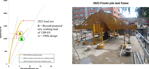
The strategy proposed by the team involved loading the existing Franki piles beyond their original design capacity, up to the concrete strength specified in 1980 (grade C25). A new load test was conducted on an abandoned two-pile group of Franki piles to verify whether the piles could handle higher loads with only minor additional settlement. Based on the concrete strength tests on Franki pile core samples by RSK, which confirmed grade C25 concrete strengths, it was estimated that the piles could carry approximately 30% more load while maintaining a stiff pile performance. Consequently, pile groups previously categorised as medium reuse risk (amber classification) were reclassified to low risk (green classification), eliminating the need for new mitigation piling at these pile group locations.
The 2023 Franki pile load test (Figure 7), by contractor Socotec at the site, was taken to loads beyond the Franki pile original design capacity and confirmed stiff pile performance based on the low measured settlements, validating the approach. The results of higher concrete strength from laboratory tests on cores taken from pile heads further supported the decision to apply higher loads to these 40-year-old Franki piles. This approach not only resulted in significant cost savings but also contributed to a more sustainable foundation strategy, with substantially reduced carbon dioxide emissions due to the reduced need for new mitigation piles. In total, 20 columns were saved from requiring new piles, resulting in a 50% reduction in the originally proposed mitigation piles.
3.5 Load and settlement performance
The load and settlement performance of the existing Franki piles was assessed by analysing both the 1980s and 2023 test data, alongside similar case study data from other Franki pile load tests conducted in the area. It was noted that the stiffness of the piles was affected by the driving of adjacent piles, leading to increased settlements in larger pile groups. To mitigate this, approximately 10–15% of the existing columns required reinforcement, combining both the existing Franki piles and new mitigation piles stitched together into a single pile cap system.
The new mitigation piles were raking mini piles up to 30 m deep. These piles were intentionally raked from the pile cap to avoid disturbing the densified gravel zone created 40 years ago, while still allowing efficient pile cap design for the integration of new and old components. A crucial aspect of the collaboration between HTS and Arup was the numerical modelling of the load distribution between the new mitigation piles and the existing Franki piles, ensuring the latter were not overstressed.
Arup’s geotechnical numerical modelling, conducted using Oasys LS-Dyna (Oasys Ltd, 2023a), was calibrated to the 1980 pile test results (Frankipile Ltd, 1980) and accounted for the reduced stiffness caused by the proximity of adjacent piles. The LS-Dyna results were then integrated into a structural model using Oasys GSA (Oasys Ltd, 2023b) to evaluate the load distribution across both new and existing piles, providing critical insights into the structural performance of the combined pile caps. This modelling helped determine the exact number of new mitigation piles required based on load split results across the pile types and provided a clearer understanding of the building’s movement under the applied loads, with the predicted pile group and column settlements used to set trigger levels within the construction monitoring system.
3.6 Construction and monitoring
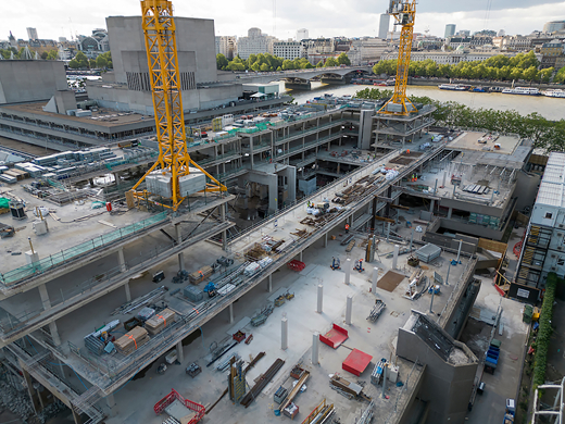
Given the sensitivity of the reuse scheme and the need to protect the ‘live’ Franki piles, a construction-focused and sustainable design solution was essential. An early assessment of the existing Franki pile capacities compared with the new applied loads indicated that certain column locations would require new mitigation piles (red classification). The scheme’s feasibility hinged on ensuring that the installation of these new piles did not compromise the load-bearing capacity of the existing Franki piles. The team developed a method (Figure 8) to install temporary casings and augers into 6 m of water-bearing gravels without disturbing the surrounding ground, which could have otherwise had severe consequences for the structure.
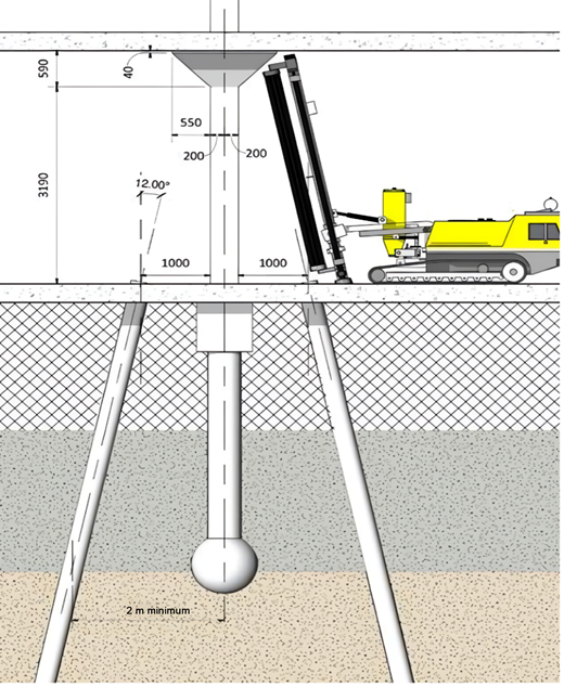
To prevent piling too close to the densified gravel zone around the Franki pile bulbs, while still minimising the load transfer distance from the column to the new piles, a raked mini pile system was adopted and installed by contractor Keller. This approach required specialised, low-headroom piling rigs operating beneath the first-floor ceiling. A monitoring system consisting of reflective targets on all existing columns was implemented by contractor SES in order to control any nearby building movements during the construction works.
The HTS–Arup–Keltbray/Keller team held early workshops to address the various constraints of the piling process. Unconventional measures were adopted, such as a drilling method that retained gravel on the auger flights until the London Clay layer was cased off. The team also avoided overspinning augers or adding water, and employed electric rigs to minimise disruption. Advance trials with ground movement monitoring were conducted, and load tests were performed on new mini piles with very small diameters. Keller proposed removing the temporary pile casings under controlled pressure, allowing the pile grout to permeate the gravels and achieve greater capacity. These efforts proved successful, with no impact on nearby Franki piles.
Keltbray managed the site monitoring conducted by SES for the enabling works, which included probing for unexploded ordnance at new pile locations, basement core demolition and extra floor plate loading. The basement core unloading resulted in a recorded heave of 20 mm, which is expected to reverse once the final retrofit loading is completed by the main contractor Multiplex. Nearby Franki piles experienced less than 5 mm of settlement due to the additional floor plate loading, and the basement works did not induce any further movement in the piles.
4. Durability risk management in existing structures
Effective management of durability risks in structural refurbishment requires a balanced approach that integrates performance risk assessments with comprehensive diagnostics and materials science to inform repair methodologies. At 76 Southbank, Multiplex instigated a four-stage strategy to ensure the building’s continued functionality and safety. This approach provided the client with a clear understanding of the asset’s condition and potential risks, and also established capital requirements for future maintenance, extending the building’s service life and preserving its value as a sustainable asset.
4.1 Enhanced diagnostics
The process began with an ‘enhanced diagnostic’ phase overseen by materials science consultancy GBG. This initial stage included a broadened scope of visual and intrusive investigations (Table 1) to identify structural defects and assess levels of chemical ingress that could threaten long-term durability.
Materials sampling and testing quantum
| Initial | Broadened/enhanced | |
|---|---|---|
| Concrete core sampling | ||
| Compressive strength Density Some samples subject to further chemical testing | 23 | 160 |
| Carbonation (structure and façade) | 22 | 57 |
| Cement content | 5 | 26 |
| Chloride content | 5 | 31 |
| Sulfate content | 5 | 31 |
| High-alumina cement | — | 8 |
| Alkali–silica reaction | — | 20 |
| Reinforcement tensile strength | 3 | 78 |
The visual and non-intrusive tests included
- ▪
visual inspections to identify defects and validate details from record drawings
- ▪
hammer-tap testing to evaluate concrete integrity
- ▪
impulse radar surveys to uncover potential hidden anomalies
- ▪
covermeter scanning to measure as-built cover depths
- ▪
direct measurements of element geometry.
Intrusive testing included
- ▪
coring for laboratory testing to determine properties such as compressive strength and density
- ▪
concrete dust sampling to analyse levels of chlorides, sulfides, alkaline and high-alumina cement content
- ▪
petrographic visual examination with up to 3000× magnification and polarised UV lighting material characterisation
- ▪
in situ carbonation testing.
4.2 Service life evaluation and planning
In the subsequent ‘service life evaluation and planning’ phase, GBG utilised the test data to calculate the remaining durable service life of the structural elements. This involved estimating the timeframe for chemical ingress to reach the reinforcement. While internal slabs and columns posed negligible corrosion risks, certain ground-contact concrete elements presented moderate risk.
An additional benefit of the data was the statistically significant confirmation that the compressive strength of concrete columns exceeded expectations, allowing HTS to further reduce the scope of column-strengthening works.
4.3 Targeted rectification and quality assurance
During the ‘targeted rectification’ phase, the team addressed both structural and cosmetic deficiencies. GBG played a critical role by recommending appropriate repair methodologies and overseeing their execution.
Tests (Figure 9) on concrete cover, carbonation and chloride content in superstructure elements indicated a low to negligible risk of significant reinforcement corrosion. However, for ground-contact elements, such as the diaphragm wall, chloride ingress posed a moderate to high risk.
Waterproofing, corrosion inhibitors and cathodic protection were considered but deemed uneconomical. Instead, HTS assessed the diaphragm wall assuming complete loss of reinforcement on the outer face. The analysis confirmed that, as tension occurs only on the inner face, the residual capacity remained sufficient for retained loads, requiring no immediate intervention.
Other structural elements, such as external columns and retained precast façade components, also presented elevated durability risks. While options like external sealants were explored, their application was determined to be impractical due to access challenges and safety considerations. Instead, these elements were identified as part of the building’s operations and maintenance strategy.
4.4 Long-term maintenance planning
The final phase focused on managing structural elements that did not require immediate rectification but warranted ongoing assessment to balance cost efficiency and long-term durability. Rather than implementing unnecessary repairs, the strategy flagged potential risks for monitoring, allowing capital expenditures to be deferred until necessary.
Following appraisal with the client, elements such as the diaphragm wall were highlighted for incorporation into the building’s operations and maintenance regime for periodic inspection. Since structural analysis confirmed its adequacy without outer-face reinforcement, intervention will only be necessary if deterioration exceeds empirical projections. Similarly, other elements identified for durability monitoring, including external columns and retained precast façade components, ensure resources are allocated efficiently over the building’s extended lifespan.
This proactive approach optimises maintenance costs by enabling early detection and risk-based prioritisation of repairs. By balancing structural resilience with cost efficiency, the project provides a replicable model for managing adaptive reuse developments.
4.5 Ownership of risk enabled through materials science
Materials science played a crucial role throughout the project. GBG’s findings influenced decisions on repair materials and techniques, ensuring compatibility with the building’s existing conditions and service life aspirations.
Clear delineation of ownership and responsibilities (Table 2) was crucial to mitigating durability and safety risks. Specific roles were assigned to ensure all parties were aware of their responsibilities in maintaining the structural integrity of the building. This included monitoring elements identified as moderate risk and adjusting the maintenance strategy as necessary. Ownership of these risks is often misunderstood within client and project teams, especially at boundary intersections.
Risk ownership matrix
| Structural performance | Fire performance | New service life (durability)c | Genuine/latent defects | |
|---|---|---|---|---|
| New structural elements | Structural engineer | Structural engineer | Structural engineer | Trade contractor |
| Existing (retained) structural elements where strengthened | Structural engineer | Fire engineer/structural engineer/architectb | Materials consultant/structural engineer | Trade contractor/insurance policy |
| Existing (retained) structural elements where subject to a change in design load or function | Structural engineer | Fire engineer/Structural engineer/architectb | Materials consultant | Insurance policy |
| Existing (retained) structural elements | Structural engineera | — | Materials consultant | Insurance policy |
Highlighted items may require changes and variation dependent on scope preferences, notation and so on
Depending on the element, protection will be specified by the structural engineer (i.e. cover requirements to concrete elements)
Generally assumed that the building's new service life matches Eurocode requirements
By setting out clear responsibilities for the structural elements, durability and safety risks were mitigated while ensuring that the project met its performance and longevity goals. Each stakeholder, from structural engineers to fire engineers and trade contractors, was fully informed of their role in navigating the complex challenges of refurbishment. This collaborative approach ensured the project complied with all required safety, performance and durability standards.
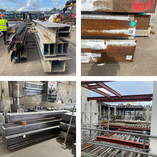
5. Novel use of reused steel
The 76 Southbank project successfully integrated reused structural steel sections, which is different from conventional steel recycling. Reused steel involves salvaging and repurposing steel sections from existing structures, thus reducing reliance on new materials and significantly cutting embodied carbon dioxide associated with steel production. The reused steel was virtually indistinguishable from new sections, demonstrating its viability in high-profile construction projects.
The process (Figure 10) began with carefully removing steel sections from existing structures. European Metal Recycling, the project’s key partner in steel reuse, managed the salvaging and testing operations. After extraction, each section underwent rigorous testing to confirm its dimensional and mechanical properties. A significant innovation in this project was the development of the material passporting system (Table 3), enabling lifetime tracking of each steel section. The material passports documented essential details for each section.
Key details recorded in reuse passporting
| Category | Details recorded |
|---|---|
| Original application | Source structure, historical use and prior loading conditions |
| Dimensional verification | Web and flange thickness and section depths. Level of conformity with tolerances |
| Certified mechanical properties | Yield strength, tensile strength, elongation and compliance with Eurocodes |
| Inspection and testing reports | Visual inspections, non-destructive testing and hardness testing |
| Surface condition | Corrosion levels, coatings and any required surface treatment |
| Fabrication features | Existing bolt holes, stiffeners and prior modifications |
| Structural classification | Fully compliant sections and those needing minor adaptation |
| Project certification | Structural engineer approval (HTS) confirming fitness for reuse |
This level of traceability not only ensured compliance with building codes but also serves as a reliable process for facilitating broader reuse by setting a standard for providing a comprehensive record of each section’s history. The introduction of material passporting set a new benchmark for how reclaimed materials can be documented and tracked for ongoing use in the construction industry.
HTS developed the Stockmatcher digital tool (HTS, 2023) to further streamline the process of matching reclaimed steel sections to the specific requirements of the 76 Southbank design. This tool allowed the design team to efficiently identify suitable reused sections, reducing the reliance on newly fabricated steel while maintaining the structural performance and integrity of the building.
Before procurement, the steel sections underwent a detailed approval process. First, each section was visually inspected to ensure it met the project’s aesthetic requirements, considering factors such as existing stiffener plates and bolt holes. Following this inspection, a multi-disciplinary review was conducted to verify that the sections satisfied both structural and aesthetic criteria.
Once approved, the steel sections were prepared for reuse. This involved removing old paint, cutting the sections to size and issuing them to the steel subcontractor for final refinishing. This stage included making adjustments to the connections, repainting and performing any necessary fabrication work. Finally, the reused steel was installed on site, integrating seamlessly with newly fabricated sections.
The building required 198 t of structural steel below the roof level, primarily located between the two cores that support the lobby and stairs – areas where the steel is architecturally exposed. Of this total, 35 t (≈15%) was reused steel, resulting in a reduction of 60 t of carbon dioxide compared with an all-new steel alternative. This calculation was based on 1850 kgCO2e/t for new steel (basic oxygen furnace) and 47 kgCO2e/t for reused steel.
Reused steel is generally comparable in cost to new steel, although recent trends show a small premium for reused materials. Additionally, Lambeth Council mandates (LC, 2025) a carbon offset price of £2850 per tonne over a 30-year period. This translates to a potential cost saving of £171 000 in carbon offsets, making the economic case for reuse even stronger. Remarkably, once painted, the exposed sections of reused steel can appear largely indistinguishable from new steel, demonstrating the feasibility of using reused materials in high-aesthetic applications.
6. Broader sustainability considerations
Sustainability in refurbishment projects encompasses not only environmental impacts but also community and workforce challenges. These projects often involve significant demolition activities (Figure 11), which can present more complex issues than new-build construction.
Intensive operations like cutting and drilling can increase noise and dust disturbances, as was the case at 76 Southbank, where measures were taken to coordinate works around performances at the National Theatre. Effective noise and dust monitoring and communication with neighbours were essential for managing community relations.
In addition, health and safety risks, such as hand–arm vibration syndrome, were mitigated by scheduling abrasive activities to minimise workers’ daily exposure levels. Adopting a comprehensive approach that incorporates environmental stewardship, social responsibility and worker safety not only enhances sustainability but also considers the well-being of both the community and the workforce involved in refurbishment projects.
7. Call to action
The achievements of the 76 Southbank project highlight the urgent need for the insurance industry to adapt to the evolving landscape of sustainable construction. An approach based on materials science to understand the durability risks of retained elements can provide the certainty needed for insurance policies that support sustainable refurbishment. By adopting these advanced methodologies, insurers can play a crucial role in enabling more projects like 76 Southbank, addressing the risk of stranded assets in the current economic climate.
The insurance industry is urged to recognise the value of such innovative approaches and to develop policies that encourage the retention and refurbishment of existing structures. This will not only mitigate environmental impacts but also preserve cultural heritage and meet the growing demand for refurbishment of buildings at risk of becoming stranded assets.
8. Conclusions
The 76 Southbank project serves as a model for sustainable building engineering, showcasing what can be achieved when ambition, innovation and collaboration come together. This project not only preserved a significant historic structure but also redefined sustainable refurbishment, setting new industry benchmarks.
A key factor in delivering a lean, efficient and sustainable design was establishing confidence in the existing structure and foundations. Access to Arup’s extensive archival records, which included original structural calculations, as-built foundation and superstructure records, contractor reports and geotechnical data, played a crucial role in this process. These records provided a valuable starting point, allowing the design team to validate key assumptions and maximise the retention of existing elements.
While archival records are helpful, they are not sufficient to fully mitigate risks in an adaptive reuse project. They do not take into account construction tolerances, actual structural movements over time and the durability of materials after decades of service. This is often a contentious issue in insurance. This highlights a significant challenge for the industry: reliance on legacy documentation must be complemented by systematic materials testing and surveys to ensure confidence in reuse strategies.
One of the largest barriers to the wider adoption of adaptive reuse is insurance coverage. Insurers are often hesitant to underwrite these projects due to uncertainties surrounding the structural reliability of retained elements. This lack of confidence can lead to restrictive policies, higher premiums or outright refusal of coverage, discouraging developers from choosing refurbishment over demolition.
The authors suggest that the rigorous materials testing and structural validation methods demonstrated at 76 Southbank can help change this perception. By quantifying materials performance and structural reliability, these approaches provide insurers with the data they need to make informed decisions based on actual risk rather than conservative assumptions. If widely adopted, this could enable the development of more tailored insurance policies that reflect the true condition of retained structures, ultimately unlocking more opportunities for adaptive reuse.
The 76 Southbank project highlights how a holistic approach combining materials science, on-site verification and structural analysis can enhance certainty, mitigate risk and create opportunities for sustainable refurbishment. By adopting these methods, the industry can move beyond reliance on historical records alone, making adaptive reuse more viable, scalable and insurable for future projects.
8.1 Breakthroughs in sustainability
A standout achievement was the successful adoption of reused steel and the development of the passporting process. Through multi-disciplinary collaboration, the project leveraged the Stockmatcher tool and material passporting to integrate 35 t of salvaged steel, ensuring full traceability and compliance with modern standards. This saved 60 t of carbon dioxide while demonstrating that reuse can deliver structural performance plus architectural appeal.
8.2 Power of collaborative excellence
The 76 Southbank project demonstrated how multi-disciplinary collaboration can drive both sustainability and commercial viability. HTS’s structural assessments, combined with GBG’s material investigations, enabled targeted strengthening rather than wholesale replacement, while Arup’s foundation reuse strategy safely retained 95% of the Franki piles, eliminating the need for extensive new piling. This minimised demolition, accelerated construction and preserved retained floor space, reducing both materials costs and embodied carbon dioxide per square metre.
By ensuring the project met high sustainability standards, the reuse strategy positioned the building within the ‘flight to quality’ market, where premium occupiers prioritise highly sustainable office spaces (Figure 12). This reinforces that structural reuse is not just an environmental choice but a commercially strategic one, unlocking value through reduced capital costs, enhanced sustainability credentials and increased market appeal.
Nick Jarman, Senior Development Director at Stanhope, said:
Building for the future means honouring the past while embracing innovation – 76 Southbank embodies these aims perfectly. Designing through the lens of sustainability, innovative technologies and construction methods have been employed in order to keep carbon levels to a minimum. A significant effort has been made by the team in restoring this heritage landmark and reimagining the building for future occupiers for generations to come. We congratulate them for successfully reaching this milestone.


Acknowledgements
The authors gratefully acknowledge Wolfe Asset Management (client), Stanhope (development manager), AHMM (architect), Heyne Tillett Steel (structural engineer), Arup (geotechnical engineer), GBG (materials science consultancy), Multiplex (main contractor), Keltbray (demolition and frame subcontractor), Keller Ground Engineering (piling subcontractor), Socotec (pile testing), WJ Groundwater (groundwater engineer) and European Metal Recycling (reused steel supplier). They also extend thanks to all other individuals and organisations whose contributions were integral to the successful completion of this project.
