By using an electronic database consisting of previously tested pile data and ten completed full-scale pile tests in Iowa, USA, load and resistance factor design (LRFD) resistance factors considering various construction control methods and set-ups were developed. The focus of this paper is on technology transfer from research to practice as the resistance factors derived at the end of the research required modifications. In a collaboration between a state agency, a private company and a university, this effort facilitated the development of a pragmatic LRFD design guide considering the pile set-up phenomenon that is suitable for use by design engineers. A summary of the joint effort and details of the end product as a lesson for other transportation agencies and similar future endeavours is presented in this paper, which highlights the steps beyond research needed to make the research outcomes valuable for practical use in design and construction while promoting the use of the LRFD principle for pile design.
Notation
- C
rate of pile set-up
- D
depth in feet below the bottom of footing
- DD
downdrag load
- DL
required embedded pile length
- Fset-up
pile set-up factor
- L
contract pile length
- li
cohesive soil thickness
- Na
average standard penetration test N value
- Ni
measured uncorrected N value
- n
total of cohesive layers along an embedded pile length
- Pu
structural resistance
- Qi
applied load
- REOD
nominal pile resistance evaluated at the end of driving
- Re
estimated pile resistance using the Iowa Blue Book method
- Rm
measured pile resistance determined from static load test based on Davisson’s criterion
- Rn
nominal pile resistance
- Rndr
target nominal pile driving resistance
- Rset-up
gain in nominal pile resistance due to pile set-up
- Rt
total nominal resistance
- T
pile set-up time after the end of driving
- tEOD
time at the end of driving
- γDD
load factor for downdrag load
- γi
load factor
- σ
structural service stress
- φ
resistance factor
- φEOD
resistance factor for R EOD
- φset-up
resistance factor for R set-up
Introduction
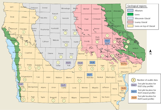
In response to the Federal Highway Administration mandate that all new bridges initiated after 1 October 2007 be designed according to the load and resistance factor design (LRFD) approach, a comprehensive research programme for developing cost-effective LRFD procedures for bridge piles in Iowa has been successfully completed. The research programme has generated new knowledge for driven pile foundations as assimilated in the project website (Sritharan, 2017). The research programme developed the comprehensive electronic database Pile Load Tests (Pilot) by Roling et al. (2010, 2011), completed ten full-scale pile load tests in the field adjacent to bridge sites (Ng et al., 2011) and established regional LRFD resistance factors with consideration of various construction control methods and pile set-ups documented in the report by AbdelSalam et al. (2012). The Pilot database contains data from 264 static pile load tests, conducted between 1966 and 1989 in Iowa, and was compiled electronically using Microsoft Office Access to establish quality-assured and usable static load test data on piles for use in LRFD calibrations through a quality-assurance programme. Of the 264 load test records, 32 pile records as summarised in Table 1 have sufficient hammer, driving, pile and subsurface information for wave equation analysis programme (WEAP) analyses and LRFD resistance factor calibration. Besides the historical data, ten full-scale field tests (denoted as ISU1 to ISU10) on the most commonly used steel H-piles were conducted at bridge construction sites throughout Iowa to cover all geological regions as shown in Figure 1. Table 2 summarises the main soil profiles, piles, hammers and pile resistances determined at both the end of driving (EOD) and the beginning of the last restrike (BOR). Figure 1 illustrates the locations of 32 usable historical pile records and the ten full-scale pile load tests. Five of these test piles were installed in cohesive soils (ISU2 to ISU6), two in non-cohesive soils (ISU9 and ISU10) and the remaining three in mixed soils (ISU1, ISU7 and ISU8). These field tests involved detailed site characterisation using both in situ subsurface investigations and laboratory soil tests. Test piles were instrumented with strain gauges and monitored using the pile driving analyzer (PDA) system during pile installations and restrikes that were performed to investigate the influence of pile set-up. After completing all restrikes on the test piles, vertical static load tests were performed on test piles following the ‘quick test’ – the ASTM D 1143 procedure (ASTM, 2007) – and the ultimate pile capacity (Rm) in all cases, including those for the historical tests, was defined using Davisson’s (1972) criterion. Pile resistances were analysed using the locally developed static analysis method known as the Iowa Blue Book method, WEAP and the Case Pile Wave Analysis Program (Capwap). The Iowa Blue Book method combines the α-method (Tomlinson, 1971) for cohesive soil materials and the Meyerhof (1976) semi-empirical method for cohesionless soil materials (Dirks and Kam, 1994). Using both the historical data and field test results, regional LRFD resistance factors were developed, following the American Association of State Highway and Transportation Officials (AASHTO) LRFD framework. Among the various static methods, the Iowa Blue Book method, which is the most efficient method, having the highest efficiency factor (AbdelSalam et al., 2012), was recommended for pile design, while WEAP and Capwap were chosen for pile construction control.
The Pilot database in Table 1 and the field test results in Table 2 show that steel H-piles installed in cohesive soils exhibited increases in resistances after the EOD due to set-up by an average of 50% in 7 d. It was further observed that these piles exhibited a logarithmic set-up trend, in which the pile resistance increased immediately and rapidly within a day after EOD and continuously increased at a slower rate after the second day (Ng et al., 2013a). To increase the efficiency of driven pile foundations, a readily applicable pile set-up resistance quantitative method was developed by Ng et al. (2013b) and incorporated into the LRFD framework to achieve the desired target reliability index (Ng and Sritharan, 2015). A study conducted by Ng et al. (2012) on 604 production steel H-piles, driven in cohesive soils between 2009 and 2010 in Iowa, concluded that the incorporation of pile set-up into the LRFD procedure reduced the target driving resistance by about 17% and the number of pile retaps from 37 to 15%. It further found that the recommended LRFD procedure would not significantly increase the design and construction costs of driven pile foundations. In fact, it provides economic advantages to the bridge foundations (Ng et al., 2012) by reducing the need for pile retaps.
The benefits can be realised only if the cost-effective and advanced LRFD procedure can be readily adopted and implemented by bridge engineers in future bridge foundations. To facilitate technology transfer and enable the application of the advanced LRFD procedures, a pragmatic design guide that aligns with the current Iowa Department of Transportation (Iowa DOT) LRFD Bridge Design Manual (BDM) (Iowa DOT, 2011) as well as AASHTO’s (2012)LRFD Bridge Design Specifications was developed by the Green et al. (2012). The application of the design guide is demonstrated using 12 step-by-step pile design examples in three different tracks, depending on the construction control method chosen for verifying the pile resistance in the field. In each track, piles are designed using the Iowa Blue Book method. The pile driving criteria are established using WEAP in track 1, the modified Iowa Engineering News Record (ENR) formula in track 2 and a combination of WEAP and PDA with a subsequent pile signal matching analysis using Capwap in track 3. The track examples cover four different pile types, three different soil categories and four special design considerations. The design guide was developed to include (a) the strength limit state and resistance equations, (b) recommended resistance factors for design and construction control with appropriate modifications, (c) a new well-defined soil classification, (d ) the standardised templates and instructions for computer-aided design and drafting (Cadd) as well as driving notes for abutment piles and pier piles and (e) standardised design and construction steps. In each example, steps required to complete the geotechnical design for vertical loads and construction control are described. Due to space limitations, one example of steel H-piles embedded in a cohesive soil category following the track 1 procedure is presented herein, and results obtained from three tracks are compared. A summary of the track examples is presented in Table 3, while the detailed descriptions are documented in volume IV of the LRFD report (Green et al., 2012). Other considerations including scour, downdrag, uplift and end bearing in bedrock are illustrated in track 1. Since the research focused on an axially loaded single pile, the lateral resistance of piles, seismic design and pile group effects in terms of capacity reduction and differential settlement were not considered in the development of these design examples. It is recommended to refer to AASHTO’s (2012)LRFD Bridge Design Specifications for these special design considerations. The design guide and track examples will only serve as a reference for future revisions for the relevant sections of the Iowa DOT’s (2011) BDM. Although the LRFD design guides and examples were developed for the state of Iowa, they can be adopted by other national and international agencies.
Design guide
Overview
The design guide was developed by assimilating the outcomes of the LRFD research programme (AbdelSalam et al., 2012; Ng et al., 2011; Roling et al., 2010) with the current Iowa DOT’s (2011) BDM and the AASHTO’s (2012) LRFD Bridge Design Specifications. This design guide reflects the current bridge foundation design and construction practices in Iowa and local soil conditions.
Strength limit state and resistance equation
Similar to the AASHTO LRFD framework and current Iowa DOT’s (2011) BDM, the guide follows the LRFD strength limit state Equation 1 for the bridge foundation design. The nominal pile resistance R n is determined using Equation 2 by rearranging Equation 1, from which the contract pile length is calculated
where γ i is a load factor as recommended by the AASHTO (2012) corresponding to the applied load Qi, γ DD is a load factor of 1·0 for downdrag load D D, φ is a resistance factor for pile design using the Iowa Blue Book method chosen from Table 4 and R n is a nominal pile resistance at the EOD.
Pile performance is verified in the field in terms of a target nominal pile driving resistance (R ndr) at EOD, depending on the specified construction control method and the embedded soil category. The pile performance is accepted when the measured pile resistance is greater than the calculated R ndr. For piles installed in a non-cohesive or mixed-soil category, no pile set-up is considered and the R ndr is evaluated at EOD by Equation 3, where φ is the resistance factor chosen from Table 5
For driven piles installed in a cohesive soil category, pile set-up consideration is recommended and the R ndr is scaled back and evaluated at EOD by Equation 4, considering a selected set-up time (T) after EOD. Equation 4 is derived from an expanded strength limit state (Equation 5) proposed by Ng and Sritharan (2015), and by replacing the pile set-up resistance (R set-up) using Equation 7. The strength limit state equation was expanded to account for different uncertainties associated with the nominal resistance at EOD (R EOD) estimated using the Iowa Blue Book method and R set-up determined by Equations 6 and 7. Equation 6 is applicable only to pile set-up estimation when WEAP is used as the construction control method
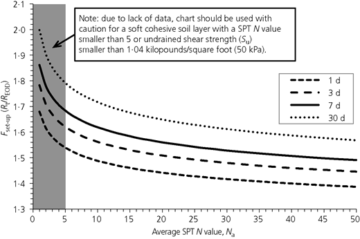
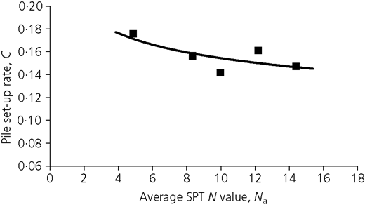
where φ EOD is a resistance factor chosen from Table 5 for nominal resistance evaluated at EOD (R EOD); φ set-up is a resistance factor chosen from Table 5 for gain in nominal resistance due to pile set-up (R set-up) at time T (days) after EOD; F set-up is a set-up factor, the ratio of total nominal resistance (R t) including set-up to nominal resistance at EOD (R EOD), determined from Equation 6 or Figure 2 based on average standard penetration test (SPT) N value (N a) and a desired set-up time t (days) after EOD; N a is an average SPT N value calculated by weighting the measured uncorrected N value (Ni) at each cohesive soil layer i along the pile shaft by its thickness (li) for a total of (n) cohesive layers situated along the embedded pile length, or . An average set-up time (t) of 7 d is recommended since most static load tests recorded in the Pilot database were performed at this time (see Table 1). A set-up time of up to 30 d is recommended since Equation 6 was developed using the static load test results obtained at durations ranging from 9 to 36 d (see Table 2 for ISU2 to ISU6). However, the F set-up factor can be determined using Equation 6 with caution if a higher set-up time of more than 30 d is desired. In order to satisfy the logarithmic relationship and to consider the immediate gain in pile resistance measured after EOD, the time at EOD (t EOD) was comfortably assumed to be 1 min (0·000 693 d). The pile set-up was correlated with the SPT N value because SPT is the most common in situ site investigation method in the USA and other countries. Furthermore, the rate of pile set-up (C) given in Equation 6 was found to have a reasonable relationship with the N a value as illustrated in Figure 3 based on the field results of five test piles in cohesive soils completed by Ng et al. (2011). The proposed pile set-up estimation is applicable to driven piles, in particular steel H-piles, but not to bored piles
Recommended resistance factors
Using the Pilot database and ten field tests on driven piles, resistance factors were calculated using a probability-based reliability theory, but further adjustments were needed. Unlike the resistance factors recommended by AASHTO (2012), construction control and set-up were considered in the calibration of resistance factors as recommended in Table 4 for design using the Iowa Blue Book method and Table 5 for construction control. The rationales used to calibrate the resistance factors statistically and adjust the calibrated resistance factors are described in the footnote of each table, while detailed descriptions are included in volume III of the LRFD report (AbdelSalam et al., 2012). The notable adjustments include not permitting the Iowa ENR formula to provide more efficient pile design than that of the WEAP approach and for the mixed-soil class to have a larger resistance factor than that of the cohesive soil to avoid the potential preference towards mixed-soil classification. The resistance factor chosen for design depends on the type of soil categories along an embedded pile length and the construction control that will be specified on the plans to achieve the target nominal driving resistance. Table 4 indicates that the resistance factors account for resistance capacity gain due to pile set-up for friction pile driven in cohesive soil. Pile set-up is ignored conservatively for friction pile driven in non-cohesive and mixed-soil categories. Calibration of the resistance factors was based on the target nominal resistance capacity that is achieved at 7 d, on average, after EOD. To accommodate typical Iowa DOT construction practice, it was suggested that scheduled retap tests for construction control should be completed 3 d after EOD. The 3-d retap was suggested since pile set-up occurred primarily in the first 3 d after the EOD, and a smaller gain in pile resistance was observed after the third day from the full-scale field experiment study by Ng et al. (2011).
Soil category classification
A consistent guideline for identifying soil types and classifying the appropriate soil category described by Green et al. (2012) was adopted in the calibration of resistance factors. To determine which generalised soil category governs, the cumulative length of cohesive and non-cohesive soil should be determined over the penetration length for the entire pile while ignoring presence of any soft soil layer (AbdelSalam et al., 2011). Then, the soil class is defined as
the cohesive category when at least 70% of the cumulative embedment pile length is estimated to penetrate cohesive soil
the non-cohesive category when no more than 30% of the cumulative embedment pile length is found to penetrate cohesive soil
the mixed category when 31–69% of the cumulative embedment pile length is in cohesive soil.
The generalised soil category applies only to the side-friction component of geotechnical pile resistance. The end-bearing component of geotechnical pile resistance is based solely on the soil stratum in which the pile is tipped out. The 70% rule is an appropriate means for defining the soil type at the site while maintaining simplicity in the design procedure (AbdelSalam et al., 2011).
Standardised Cadd note template
Standardised Cadd note templates for abutment piles and pier piles were prepared to summarise and present pile design requirements and driving criteria on drawings and plans. These standardised Cadd notes serve to communicate clearly the design and construction control requirements on plans so as to avoid confusion and facilitate construction. The appropriate Cadd notes are selected and the specific pile load values are added to the notes. These notes are replicated using the same typeface throughout the examples. These Cadd notes and instructions are included in the Appendix while they are explicitly described in volume IV of the LRFD report (Green et al., 2012).
Pile design and construction steps
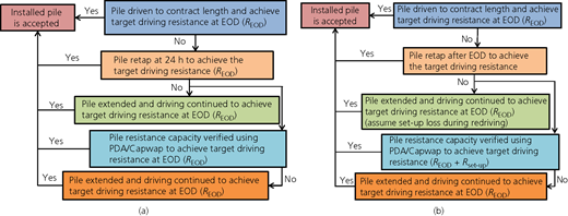
Standardised pile design and construction steps are summarised in the section headed ‘Design examples’ to reflect the real-world design and construction procedures suggested for driven pile foundations. These steps form the basis for developing the step-by-step LRFD examples. The basic information necessary for geotechnical design of a driven pile is determined from steps 1 through 3. The nominal and factored geotechnical resistances and the required contract pile length are determined from steps 4 through 7. The target pile driving information is determined in step 8, and the determined design information is summarised in the standardised Cadd notes in step 9. The design stage is concluded with final design checks in step 10. During the construction stage, pile performance is verified in step 11. Pile construction is monitored, driving is recorded and any construction issues are resolved in step 12. These 12 steps are summarised in Table 6. Pile performance is examined and accepted following the flow charts given in Figure 4(a) for end-bearing piles or friction piles embedded in non-cohesive and mixed-soil categories and Figure 4(b) for friction piles embedded in cohesive soil considering set-up.
Design examples
Overview
Following the formulation of the design guide summarised earlier, 11 examples were developed to illustrate the LRFD design and construction procedures for driven pile foundations in order to assist with the design process of different pile and soil types (see Table 3). They were arranged in three tracks. Track 1 consists of seven design examples that use WEAP to define the pile driving criteria. WEAP is the primary construction control method because it is less expensive, and the performance of 100% production piles can be evaluated during construction. Pile, hammer, hammer blow count and soil profile are normally available, making WEAP a practical method for the construction control. Track 1 also includes examples for three pile types (H-pile, pipe pile and prestressed concrete pile), three soil types (cohesive, non-cohesive and mixed) and four special design considerations (scour, downdrag, uplift and end bearing in bedrock). Track 2 consists of two examples that use the modified Iowa ENR formula to define pile driving criteria. The LRFD application to timber piles is also demonstrated in this track. The modified Iowa ENR formula is the least accurate construction control method because it poorly represents the driving system, neglects the effects of time on wave travel along a pile and assumes a rigid pile. This method was included in the track example because it has been used by resident or county engineers for more than 50 years and prior to the development of more reliable methods, such as WEAP and Capwap. Because of its simplicity, it is currently used to evaluate less-critical driven pile foundation systems, such as a temporary foundation system using timber piles. Track 3 demonstrates two design examples for projects that require special construction control procedures using PDA/Capwap, WEAP and/or scheduled retaps. PDA/Capwap is chosen when a more accurate pile performance and a distribution of soil resistances along a pile are desired. However, operational and interpretation skills are required to perform PDA/Capwap analysis. PDA/Capwap is normally used to evaluate the performance of selected test piles that cannot satisfy the LRFD strength limit state condition determined using WEAP. An example is presented here to demonstrate the steps following track 1 and compare results obtained from three tracks, while additional examples can be found in volume IV of the LRFD report (Green et al., 2012). It is important to clarify that the selection of construction control methods will not affect the determination of a contract pile length during the design stage. However, it will change the performance outcomes of production piles during construction.
Example
The example presented here briefly illustrates the design and construction steps for steel H-piles in cohesive soil following track 1 procedure by using WEAP as the construction control method. The steel H-piles are designed to support integral abutments of a 120-foot (36·6 m), single-span, prestressed concrete bridge with zero skew. Since the bridge length is less than 40 m (130 feet), no prebored holes are suggested to eliminate the downdrag effect in accordance with the Iowa DOT’s (2011) BDM specifications. The LRFD design and construction procedures are demonstrated in the following 12 steps. The application of the newly developed LRFD design guide and the design process considering pile set-up phenomenon are illustrated.
Step 1: develop a bridge situation plan
For a typical bridge, topography information, location of bridge, general type of superstructure, location of substructure units, elevations of foundations, hydraulic information and other basic information used to characterise the bridge are determined by a preliminary design engineer. This information is required in preparing a bridge situation plan.
Step 2: develop a soil package, including soil borings and foundation recommendations
Based on location of the abutments, a geotechnical engineer orders soil borings (typically at least one per substructure unit). Upon receipt of the boring logs, the engineer arranges for them to be plotted on a longitudinal section, checks any special geotechnical conditions on the site and writes a recommendation for soil classification and foundation type with any applicable special design considerations. A ‘hanging borehole’ without in situ soil testing such as SPT will be needed to classify the soil profile. However, a borehole with SPT is needed to consider pile set-up estimation. For this example, based on the soil profile at the west abutment given in Table 7, the recommendations are listed as follows
friction piles that tip out in the firm glacial clay layer to gain sufficient side resistance since the first and second layers are soft with relatively low SPT N values of 4 and 6, respectively
steel H-piles with sufficient lateral flexibility in the weak axis bending for the integral abutments to account for the expansion and contraction of the bridge due to seasonal changes.
Step 3: determine pile arrangement, pile loads and other design requirements
The abutment piles are designed with the situation plan and the soil design package. Assuming that HP 10 × 57 (HP 250 × 85) steel piles are selected, the nominal structural resistance (Pu) per pile is 243·6 kips (1083·6 kN) recommended in Iowa DOT’s (2011) BDM to limit pile settlement. Limiting the structural service stress (σ) to 6 kilopounds per square inch (ksi) (41 MPa), using a combined load factor (γ) of 1·45, and selecting a resistance factor (φ) of 0·60 for a normal driving condition, the structural resistance (Pu) is calculated as follows
For a total factored vertical load of 900 kips (4003 kN) on the abutment, seven HP 10 × 57 (HP 250 × 85) piles as calculated in Equation 9 are required plus two wing extension piles (i.e. a total of nine piles per abutment)
Step 4: estimate the nominal geotechnical resistance per foot of pile embedment
Based on the west abutment soil boring and the Iowa Blue Book method, the unit nominal geotechnical resistances for friction bearing are determined as enumerated in Table 7. According to the Iowa DOT’s (2011) BDM design table summarised in Table 8, end bearing is neglected for steel H-piles because the SPT N value of 12 at the pile tip is small. This is a conservative approach considering that the pile capacity is totally dependent on its side resistance. However, this is not true when other pile types (i.e. timber, prestressed concrete and steel pipe piles) are considered in the design as described in Table 8. In other words, end bearing of other pile types should be included in the pile capacity calculation. Furthermore, based on Iowa DOT practices, end bearing of steel H-piles will be considered when bearing in cohesive soils with SPT N values greater than 12. It is important to note that this recommendation may not necessarily be applicable to cohesive soils in other regions.
Step 5: select resistance factors to estimate pile length based on the soil profile and construction control
In this step, the site is characterised into either the cohesive, mixed or non-cohesive soil category based on the soil profile and the soil category classification method. Only the 9-foot (2·7 m) layer 2 of silty sand is classified as non-cohesive. The remainder of the profile is classified as cohesive and most likely will represent more than 70% of the pile embedment length. Thus, the soil is expected to fit the cohesive classification. The resistance factor for cohesive soil chosen from Table 4 for design is 0·65.
Step 6: calculate the required nominal pile resistance (Rn)
For a factored vertical load of 128 kips (569 kN) on each pile (i.e. 900 kips (4003 kN) over seven piles), the required nominal pile resistance determined by Equation 2 is
Step 7: estimate contract pile length (L)
Based on the nominal resistance values in steps 4 and 6, the contract pile length (L) is calculated as follows, where D = depth in feet below the bottom of footing
The required embedded pile length (DL) to achieve 197 kips (876 kN) is 73 feet (22·3 m) determined as follows
Therefore, the resistance factor for cohesive soil is the correct choice. If the resistance factor is incorrect, steps 6 and 7 should be repeated.
Step 8: estimate target nominal pile driving resistance (Rndr)
The target nominal pile driving resistance for the cohesive category is determined by Equation 4. For a driven H-pile installed in the cohesive soil with no planned retap and using WEAP, the resistance factors chosen from Table 5 for the resistance at EOD (φEOD) and the set-up resistance (φset-up) are 0·65 and 0·20, respectively. The soil profile given in Table 7 was used to calculate the average SPT N value (Na) for the cohesive soil layers penetrated by the driven pile over the embedded pile length 72 feet (22 m), as follows
Referring to Figure 2, the average SPT N value of 11 yields an Fset-up value of 1·47 for 1-d retap, 1·55 for 3-d retap and 1·61 for 7-d retap. For the recommended set-up time of 7 d, the target pile driving resistance scaled back to EOD is
If the measured pile resistance at EOD is less than the Rndr-EOD, pile retap should be performed after EOD as delineated in Figure 4(b). Due to the effect of set-up, the remeasured pile resistance should be compared with the target nominal geotechnical resistance at 1-d retap calculated as
Similarly, for 3- and 7-d retaps, the target nominal geotechnical resistances are
Step 9: prepare Cadd notes for bridge plans
At this point, the calculated pile design and construction information can be added to the Cadd notes following the templates for abutment piles described in the Appendix as follows.
Abutment piles design note
THE CONTRACT LENGTH OF 75 FEET (23 METER) FOR THE WEST ABUTMENT PILES IS BASED ON A COHESIVE SOIL CLASSIFICATION, A TOTAL FACTORED AXIAL LOAD PER PILE (Pu) OF 128 KIPS (569 KN), AND A GEOTECHNICAL RESISTANCE FACTOR (PHI) OF 0·65.
THE NOMINAL AXIAL BEARING RESISTANCE FOR CONSTRUCTION CONTROL WAS DETERMINED FROM A COHESIVE SOIL CLASSIFICATION AND A GEOTECHNICAL RESISTANCE FACTOR (PHI) OF 0·77.
Abutment piles driving note
THE REQUIRED NOMINAL AXIAL BEARING RESISTANCE FOR WEST ABUTMENT PILES IS 83 TONS (75 METRIC TONS) AT END OF DRIVE (EOD). IF RETAPS ARE NECESSARY TO ACHIEVE BEARING, THE REQUIRED NOMINAL AXIAL BEARING RESISTANCE IS 122 TONS (110 METRIC TONS) AT ONE-DAY RETAP, 129 TONS (117 METRIC TONS) AT THREE-DAY RETAP, OR 134 TONS (122 METRIC TONS) AT SEVEN-DAY RETAP. THE PILE CONTRACT LENGTH SHALL BE DRIVEN AS PER PLAN UNLESS PILES REACH REFUSAL. CONSTRUCTION CONTROL REQUIRES A WEAP ANALYSIS AND BEARING GRAPH.
Step 10: check the design
The bridge design is checked by an independent design engineer when final plans are complete. However, other design organisations may perform checks at various stages of design rather than upon plan completion.
Step 11: prepare bearing graph
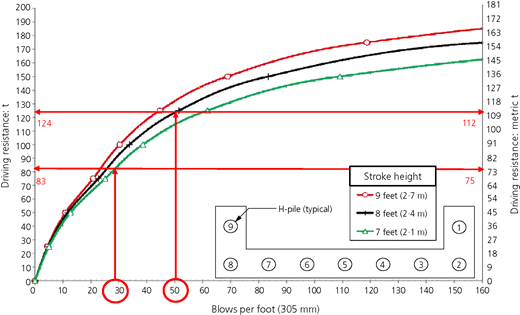
After the bridge contract is let and prior to start of pile driving, Hammer data sheets will be submitted by the contractor to include all pertinent information necessary to complete a WEAP analysis. Results from the WEAP analysis are then used to prepare an LRFD driving graph as shown in Figure 5. The bearing graph was generated using the specified pile, hammer and soil profile inputs to the WEAP. The bearing graph relates the nominal pile resistance to a driving resistance in terms of a hammer blow count. In this example, the pile type is HP 10 × 57 (HP 250 × 85), the hammer used is a single-acting diesel hammer Delmag D19-42 and the soil profile is given in Table 7.
Step 12: observe construction, record driven resistance
During pile driving, the construction inspector records the hammer stroke and number of blows to advance the pile an equivalent penetration of 1 foot (305 mm) and then converts the recorded information with the driving graph to record the driven resistance per pile at EOD. For example, the construction inspector recorded a hammer stroke of 7 feet (2·1 m) and a blow count of 29 blows per foot (29 blows per 305 mm) for the last foot of pile 4 penetration at EOD. Based on the driving graph, the construction inspector recorded a driving resistance of 82 English t (74 metric t), which is less than the target driving resistance of 83 English t (75 metric t), as shown in Figure 5. Referring to the flow chart given in Figure 4(b), pile 4 was retapped with ten hammer blows at 1 d after EOD. Pile 4 penetrated a distance of 2·4 inches (i.e. 50 blows per foot) at a hammer stroke of 8 feet (2·4 m). The pile 4 retap resulted in a retap driving resistance of 124 English t (112 metric t), which is greater than the retap target driving resistance of 122 English t (110 metric t). If pile 4 cannot reach the target nominal pile driving resistance of 122 English t (110 metric t) at the retap event, it can be spliced with an extension pile, and redriving can be continued to avoid any delay in construction. At this point, the pile set-up resistance initially developed is not taken into account. The pile can be extended until the new field measured pile driving resistance reaches the target nominal driving resistance at EOD of 83 English t (75 metric t).
Design comparison
The aforementioned design information and pile driving criteria following the track 1 procedure are summarised in Table 9 and are compared with results obtained from tracks 2 and 3 with different construction control methods. The design following track 3 requires the shortest contract steel H-pile length and the smallest target pile driving resistances at EOD (Rndr-EOD). The design following track 2 requires the longest pile length and the largest Rndr-EOD, while the design following track 1 provides a median pile contract length and Rndr-EOD. Relating the contract pile length to foundation cost, the design following track 2 will require the longest pile length and highest driving effort, which result in the highest construction cost. Comparing these three Rndr-EOD values with the same measured pile driving resistance, piles driven based on the criteria established in track 2 will be less likely to achieve the highest Rndr-EOD value. Hence, this pile will require retaps or extension, which will delay construction and incur additional construction cost.
Conclusions
The regionally calibrated LRFD procedure that incorporates pile set-up into the design and construction of bridge foundations has been found to improve the efficiency of future bridge foundation design. It was found that some of the resistance factors established following the reliability theory and field data led to inconsistent results such that it promoted a dynamic formula over WEAP for construction control. Therefore, a step for revising the resistance factors with emphasis on past experience was needed to develop suitable resistance factors. This led to a joint effort between the research team and DOT engineers and a foundation specialist to develop a design guide that enabled very effective technology transfer. This process also accounted for the current Iowa DOT (2011) BDM and AASHTO’s (2012)LRFD Bridge Design Specifications as well as integration of set-up into the design and construction practice with minimal changes to the current practice. To aid with LRFD design of driven piles, 12 step-by-step design examples were created. These examples were presented in three different tracks considering four pile types, three soil categories and four special design considerations. Although the design guide and examples were developed specifically for a regional area, the adopted process is valuable to other DOTs in developing their own LRFD guide for driven piles as well to integrate set-up.




Acknowledgements
The authors would like to thank the Iowa Highway Research Board for sponsoring the research programme.
Appendix
The proposed standardised Cadd note templates in all capital letters and instructions to complete these Cadd notes for abutment piles and pier piles are given as follows.
Abutment Piles: Design Note and Instructions
THE CONTRACT LENGTH OF ___ METER (FEET) FOR THE ___ ABUTMENT PILES IS BASED ON A ___ SOIL CLASSIFICATION, A TOTAL FACTORED AXIAL LOAD PER PILE (Pu) OF ___ KN (KIPS), AND A GEOTECHNICAL RESISTANCE FACTOR (PHI) OF ___ FOR SOIL AND ___ FOR ROCK END BEARING. TO ACCOUNT FOR SOIL CONSOLIDATION UNDER THE NEW FILL, THE FACTORED AXIAL LOAD INCLUDES A FACTORED DOWNDRAG LOAD OF ___ KN (KIPS). ABUTMENT PILES ALSO WERE DESIGNED FOR A FACTORED TENSION FORCE OF ___ KN (KIPS).
THE NOMINAL AXIAL BEARING RESISTANCE FOR CONSTRUCTION CONTROL WAS DETERMINED FROM A ___ SOIL CLASSIFICATION AND A GEOTECHNICAL RESISTANCE FACTOR (PHI) OF ___ FOR SOIL AND ___ FOR ROCK END BEARING. DESIGN SCOUR (100-YEAR) WAS ASSUMED TO AFFECT THE UPPER ___ FEET OF EMBEDDED PILE LENGTH AND CAUSE ___ KIPS OF DRIVING RESISTANCE.
Fill in the contract length (meter or ft).
Fill in abutment location (north, east, south, or west) or delete the blank if the note covers both abutments.
Fill in soil classification for design (cohesive, mixed, or non-cohesive).
Fill in the total factored axial load per pile (Pu in kN or kips).
Fill in the resistance factor (phi) for design in soil. If piles are to be driven to rock, add the resistance factor (phi) for rock; otherwise, delete the end of the sentence beginning with “for”.
If piles are subject to downdrag, fill in the factored downdrag load (kN or kips).
Fill in soil classification for construction control (cohesive, mixed, or non-cohesive).
Fill in the resistance factor for construction control (phi).
If piles were designed for scour, fill in the affected embedded length (meter or ft); otherwise, delete the sentence.
Abutment Piles: Driving Note and Instructions
THE REQUIRED NOMINAL AXIAL BEARING RESISTANCE FOR ___ ABUTMENT PILES IS ___ METRIC TONS (TONS) AT END OF DRIVE (EOD). IF RETAPS ARE NECESSARY TO ACHIEVE BEARING, THE REQUIRED NOMINAL AXIAL BEARING RESISTANCE IS ___ METRIC TONS (TONS) AT ONE-DAY RETAP, ___ METRIC TONS (TONS) AT THREE-DAY RETAP, OR ___ METRIC TONS (TONS) AT SEVEN-DAY RETAP. THE PILE CONTRACT LENGTH SHALL BE DRIVEN AS PER PLAN UNLESS PILES REACH REFUSAL. IN NO CASE SHALL A PILE BE EMBEDDED LESS THAN ___ METER (FEET). CONSTRUCTION CONTROL REQUIRES A WEAP ANALYSIS WITH BEARING GRAPH.
Fill in abutment location (north, east, south, or west) or delete the blank if the note covers both abutments.
Fill in end of drive bearing (metric tons or tons).
For clay or mixed sites, fill in retap blanks; for sand sites or piles driven to rock, delete the retap sentence. If retap is required for construction control, substitute the following sentence.
Piles must be retapped at ___ days with a required nominal axial bearing resistance of ___ metric tons (or tons).
For timber piles, replace the contract length sentence with the following.
The pile contract length shall be driven as per plan unless piles reach a driving limit of 100 metric tons (110 tons).
If piles are subject to tension, scour, or other condition requiring a minimum embedment length, fill in the length (meter or ft); otherwise, delete the sentence.
Replace the construction control sentence if a method other than WEAP without planned retap is to be used. Alternate sentences are as follows.
Construction control requires a specified dynamic formula.
Construction control requires PDA/CAPWAP and a WEAP analysis with bearing graph.
Construction control requires a WEAP analysis with bearing graph and a retap at ___ days after EOD.
Pier Piles: Design Note and Instructions
THE CONTRACT LENGTH OF ___ METER (FEET) FOR THE ___ PIER PILES IS BASED ON A ___ SOIL CLASSIFICATION, A TOTAL FACTORED AXIAL LOAD PER PILE (Pu) OF ___ KN (KIPS), AND A GEOTECHNICAL RESISTANCE FACTOR (PHI) OF ___ FOR SOIL AND ___ FOR ROCK END BEARING. TO ACCOUNT FOR SOIL CONSOLIDATION, THE FACTORED AXIAL LOAD INCLUDES A FACTORED DOWNDRAG LOAD OF ___ KN (KIPS). PIER PILES ALSO WERE DESIGNED FOR A FACTORED TENSION FORCE OF ___ KN (KIPS).
THE NOMINAL AXIAL BEARING RESISTANCE FOR CONSTRUCTION CONTROL WAS DETERMINED FROM A ___ SOIL CLASSIFICATION AND A GEOTECHNICAL RESISTANCE FACTOR (PHI) OF ___ FOR SOIL AND ___ FOR ROCK END BEARING. DESIGN SCOUR (100-YEAR) WAS ASSUMED TO AFFECT THE UPPER ___ METER (FEET) OF EMBEDDED PILE LENGTH AND CAUSE ___ KN (KIPS) OF DRIVING RESISTANCE.
Fill in the contract length (meter or ft).
Fill in abutment location (north, east, south, or west) or delete the blank if the note covers both abutments.
Fill in soil classification for design (cohesive, mixed, or non-cohesive).
Fill in the total factored axial load per pile (Pu in kN or kips).
Fill in the resistance factor (phi) for design in soil. If piles are to be driven to rock, add the resistance factor (phi) for rock; otherwise, delete the end of the sentence beginning with “for”.
If piles are subject to downdrag, fill in the factored downdrag load (kN or kips).
Fill in soil classification for construction control (cohesive, mixed, or non-cohesive).
Fill in the resistance factor for construction control (phi).
If piles were designed for scour, fill in the affected embedded length (meter or ft); otherwise, delete the sentence.
Pier Piles: Driving Note and Instructions
THE REQUIRED NOMINAL AXIAL BEARING RESISTANCE FOR PIER ___ PILES IS ___ METRIC TONS (TONS) AT END OF DRIVE. IF RETAPS ARE NECESSARY THE REQUIRED NOMINAL AXIAL BEARING RESISTANCE IS ___ METRIC TONS (TONS) AT ONE-DAY RETAP, ___ METRIC TONS (TONS) AT THREE DAY RETAP, OR ___ METRIC TONS (TONS) AT SEVEN DAY RETAP. THE PILE CONTRACT LENGTH SHALL BE DRIVEN AS PER PLAN UNLESS PILES REACH REFUSAL. IN NO CASE SHALL A PILE BE EMBEDDED LESS THAN ___ METER (FEET). CONSTRUCTION CONTROL REQUIRES A WEAP ANALYSIS AND BEARING GRAPH.
Fill in pier number (1, 2…) or delete the blank if the note covers all piers.
Fill in end of drive bearing (kN or tons).
For clay or mixed sites, fill in retap blanks; for sand sites delete retap sentence.
For clay or mixed sites, fill in retap blanks; for sand sites or piles driven to rock, delete the retap sentence. If retap is required for construction control, substitute the following sentence.
Piles must be retapped at ___ days with a required nominal axial bearing resistance of ___ metric tons (or tons).
For timber piles replace the contract length sentence with the following.
The pile contract length shall be driven as per plan unless piles reach a driving limit of 100 metric tons (110 tons).
If piles are subject to tension, scour, or other conditions requiring a minimum embedment length, fill in the length; otherwise delete the sentence.
Replace the construction control sentence if a method other than WEAP without planned retap is to be used. Alternate sentences are as follows.
Construction control requires a specified dynamic formula.
Construction control requires PDA/CAPWAP and a WEAP analysis with bearing graph.
Construction control requires a WEAP analysis with bearing graph and a retap at ___ days after EOD.