


The use of dynamic centrifuge modelling has substantially risen over the years for investigating failure mechanisms, studying the physics-based mechanics of soil–structure systems, and validating numerical tools. Nevertheless, the primary issues associated with the use of servo-hydraulic actuators (presently the prevailing shaking table for a geotechnical centrifuge) are their exorbitant expense, intricate operation, and shaking control. This paper describes the development of a novel cylindrical cam shaker for the newly installed Mark III geotechnical centrifuge facility at Tokyo City University. The cylindrical cam mechanism is activated once the desired voltage is applied by way of the electrical slip rings. The rotation of the cylindrical cam is translated into the linear motion of the follower plate, which then moves the shaker linearly back and forth. A stepwise procedure is developed to determine the voltage required to drive the shaker and achieve the desired earthquake characteristics for a given payload mass and centrifugal acceleration. The performance of the shaker was systematically assessed through a series of dynamic centrifuge experiments at different centrifugal accelerations and payload masses. Finally, the excellent capabilities of the developed mechanical shaker in terms of the repeatability of the base motions were demonstrated using a model example.
Notation
1. Introduction
The use of geotechnical centrifuges in earthquake engineering has increased enormously in recent years because of significant improvements in shaking table actuators, data sensing techniques, model containers, and model preparation procedures. This has led researchers at several universities and research institutions worldwide to use geotechnical centrifuge modelling to understand the failure/deformation mechanisms of soil–structure systems through the assessment of non-linear soil–structure deformations using different in-flight instrumentations (e.g., Adamidis and Madabhushi, 2018; Bhattacharya et al., 2004; Dashti et al., 2009; Sahare and Ueda, 2024). In addition, centrifuge modelling is also extensively used to validate the developed numerical tools and verify the accuracy of the soil constitutive models under the complex cyclic loading scenarios (e.g., Sahare et al., 2020, 2024; Sakellariadis and Anastasopoulos, 2022; Zeghal et al., 2018).
Earthquake actuators and shaking control play the most important role in realising cyclic loading of mounted model containers in a dynamic centrifuge, which can generally be classified as mechanical, piezoelectric, explosive, electromagnetic, or hydraulic (Schofield and Steedman, 1992). The first mechanical actuator used to study the geotechnical problems of seismic loading based on the pseudostatic concept was developed by Mikasa et al. (1969) in Japan. This was followed by the development of a mechanical spring actuator system by Morris (1979) and Ortiz et al. (1983), a bumpy road mechanical actuator by Kutter (1982), a piezoelectric shaker by Arulanandan et al. (1982), an eccentric cam shake table by Kimura et al. (1988), and an electromagnetic actuator by Fujii (1991). In the 1980s, researchers in the US and Japan made considerable efforts to develop electrohydraulic actuators (e.g., Kutter et al., 1994; Takemura et al., 1989).
Currently, most dynamic centrifuge facilities worldwide use a servo-hydraulic-type shaking table actuation system (e.g., Barrios et al., 2021; Boulanger et al., 2020; Loli et al., 2014; Madabhushi et al., 2012; Okamura et al., 2001; Paramasivam et al., 2018; Takahashi et al., 2020; Tobita et al., 2022; Westcott et al., 2022; Zhou et al., 2020). Although servo-hydraulic actuators provide a powerful way to excite model container mounted on a centrifuge machine with a programmable input motion through hydraulic fluid accumulators, they have certain limitations. Firstly, the overall operation of a servo-hydraulic actuator, which involves the application of oil in a scaled short duration under large stress during centrifuge spinning is very complex. Apart from the very high initial and maintenance costs, servo valves must be carefully designed for high centrifugal acceleration and should take into account the inherent features of a particular beam centrifuge (Madabhushi et al., 2012).
The next major problem when using a servo-hydraulic-type shaking table actuator is shaking control and poor reproducibility of the intended seismic input motions. Zhou et al. (2020) described three possible methods for firing a target motion during a dynamic centrifuge experiment. These methods involve either a compromise with a very different achieved motion compared with the desired targeted motion, application of multiple shakes until the achieved and target motion match resulting in a strong perturbation of the soil model, or the use of time-consuming dummy models to identify the transfer functions before the main experiment. The VELACS (Verification of Liquefaction Analysis by Centrifuge Studies) was the first of its kind project to compare the dynamic response obtained from the different centrifuge facilities for a similar standard test involving a saturated soil model under the same desired input motion (Arulanandan and Scott, 1993). Significant discrepancies were observed among the different centrifuge facilities in reproducing the target motion in terms of acceleration amplitude and high-frequency content. Notably, the Fourier amplitude of the input motions also differed considerably among the various facilities. This gave rise to deviated measured excess pore pressures and displacement responses, even for duplicate centrifuge experiments performed by the same team (Popescu and Prevost, 1995). Similar discrepancies were observed during the liquefaction experiments and analysis projects (LEAP-2015) comprising six centrifuge facilities worldwide, aiming to investigate the aspect of repeatability (Manzari et al., 2018). It is noteworthy that all of the facilities participated within the LEAP-2015 were equipped with a servo-hydraulic actuator system. Kutter et al. (2018) described the variations in the achieved input motions compared with the targeted input motions (in terms of acceleration time history and acceleration response spectra) among six centrifuge facilities. The peak base velocity achieved after performing baseline correction with a high-pass filter was only approximately 60%–70% of the targeted value for most centrifuge facilities in LEAP-2015.
This paper describes the newly installed Mark III beam centrifuge at Tokyo City University (TCU). The mechanical design, operational details, and data acquisition system of the newly introduced centrifuge machine are described in detail. This is followed by a section describing the development of a novel shaking table actuator, which is driven by a cylindrical cam mechanism. Following the working mechanism and operational details of the shaker, the performance of the mechanical actuator was evaluated through a series of centrifuge experiments for different payload masses under different centrifugal accelerations. A series of centrifuge tests were used to develop relationships between different parameters for the shaker. Finally, the reproducibility of the shaker was demonstrated.
2. New geotechnical centrifuge facility at the Tokyo City University
The newly installed Mark III beam-type geotechnical centrifuge device at TCU is shown in Figure 1. The centrifuge was manufactured by Nippon Steel Railway Technology (Japan). The centrifuge has an effective radius of 1.4 m, and payload capacity of 10 g-ton and can achieve a maximum centrifugal acceleration of 100g under static conditions (i.e., the centrifuge can carry a maximum payload of 100 kg at maximum centrifugal acceleration). The relationship between the centrifugal acceleration and the payload is shown in Figure 2. The platform area of the bucket is 0.6 m (width) × 0.8 m (length), as shown in Figure 1. Further specifications of the centrifuge are listed in Table 1.
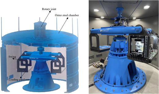
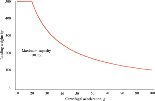
In-flight capacity of the newly developed Mark III TCU geotechnical centrifuge facility
In-flight capacity of the newly developed Mark III TCU geotechnical centrifuge facility
2.1 Mechanical design
Figures 3 and 4 show the front and top views of the newly installed TCU Mark III geotechnical centrifuge facility with the dimensions given in millimetres. In Figure 3, component 1 represents the rotating arm assembly of the beam centrifuge, component 2 is the central shaft assembly around which the centrifuge rotates, component 3 represents the drive unit assembly, component 4 is the outer cover assembly of the centrifuge body, and component 5 is the upper rotatory joint assembly. In addition, Figure 5 presents the time lapse photos during the construction of the geotechnical centrifuge and its various components. The centrifuge was located in a circular steel structure with an outer diameter of 3.55 m, below the ground surface to limit the energy released during its spin-up and for safety reasons in an event of a serious accident. To fabricate the protective circular steel structure, an underground square chamber measuring 4.1 × 4.1 m was prepared inside the newly constructed building (see Figure 5). The outer circular steel chamber was then lowered into place using a temporary crane. The reducer, servomotor, and other parts of the drive assembly were then installed on the fixed pedestal. The bottommost cone of the centrifuge facility, which houses the motor-drive assembly, was then installed. The entire drive unit weighed approximately 1618 kg. The required bearings and a vertical shaft weighing approximately 810 kg were then installed. The arm of the centrifuge, with a mass of approximately 1000 kg, was subsequently lowered and installed, as seen in Figure 5. Two swinging baskets were then attached to the horizontal arm of the centrifuge. The instrumented centrifuge payload model for the centrifuge testing can be placed on one side of the arm on the swing platform, and the counterweight on the other side of the beam, as shown in Figure 1. Finally, the circular chamber was sealed using an outer cover with a manhole with opening dimensions of 80 cm × 80 cm to facilitate the installation of the model containers during the experiments (see Figure 5). The entire outer cover body assembly weighs approximately 5870 kg.
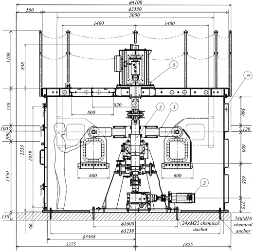
Front view of the TCU Mark III geotechnical centrifuge facility with various components (all dimensions in mm)
Front view of the TCU Mark III geotechnical centrifuge facility with various components (all dimensions in mm)
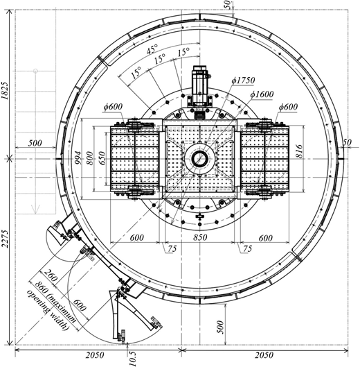
Top view of the TCU Mark III geotechnical centrifuge facility with various components (all dimensions in mm)
Top view of the TCU Mark III geotechnical centrifuge facility with various components (all dimensions in mm)
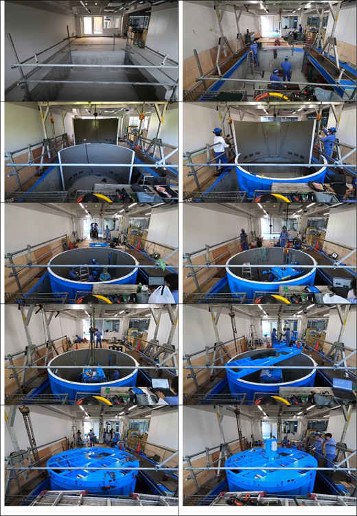
Different stages involved in the installation of the TCU Mark III geotechnical centrifuge
Different stages involved in the installation of the TCU Mark III geotechnical centrifuge
The height of the centrifuge facility room (including the slab) is approximately 2.3 m. The preparation of the model (air pluviation and saturation processes) is conducted outside the centrifuge facility chamber, and the model is then transferred to the centrifuge platform through the manhole using the in-house crane facility.
2.1.1 Servo motor
As shown in Figure 3, a 14 kW motor was installed below the rotor arm of the centrifuge (component 3) within the drive unit assembly to drive the centrifuge. The motor (manufactured by FANUC, Japan) is an AC servo-type motor based on a servo-mechanism with a voltage of 200 V, a rotation speed of 2000 rpm, and a stall torque of 95 Nm. A servo amplifier is used to drive the servo motor. The torque characteristics of the servo motor enable rapid acceleration at high speeds and shorten cyclic times. The servo motor is equipped with a smart servo control function that can optimise machine control in real time depending on several uncertainties such as the applied load and variations in the existing temperature. The rotor arm can rotate around the vertical axis at a maximum rotational speed of 252.8 rpm. A servo amplifier is used to determine the predetermined constant torque that gears the centrifuge until the desired rotational speed is reached (which depends on the desired centrifugal acceleration).
2.2 Data acquisition system
The centrifuge’s data acquisition system consists of electrical slip rings and a rotary joint. The data logger system (CTRS-100 series manufactured by Kyowa, Japan) was installed to obtain the inflight data during the centrifuge experiments. The total number of measurement channels are 32 with a maximum sampling frequency of 100 kHz. The channels within the data logger system can be used to measure the strain and voltage for the connected instrumentations through the LAN slip rings.
2.2.1 Electrical slip rings
Electrical slip rings, manufactured by Kyoei Electric, Japan, were installed near the vertical shaft of the centrifuge arm. The slip ring system consists of a three-mould type system with a power supply of 100 V and a current flow of 20 A. The overall functions of the installed slip rings can be categorised into three types: power supply, communication, and control systems with terminal blocks to establish a connection between the centrifuge and the control room.
The main function of the power slip ring is to supply power to the centrifuge by way of the installed servo motor or to the installed actuators, such as the shaking table, the tilting table, or the rainfall simulator devices. The maximum load capacity of the power-slip ring is 20 kVA. There are three connection points for the power slip rings, an AC100 V outlet, an AC100 V power supply terminal block comprising three different terminal supporting equipment compatible with 100 V, and a DC24 V power supply terminal block with two different terminal supporting equipment compatible with 24 V. A communication slip ring is used to establish a connection between the control room and centrifuge device. Communication slip rings can be used to transfer data from the data logger (connected to different sensors) on the centrifuge arm or the mounted high-speed camera to the control room by way of a high-speed LAN connection. The data can be transferred to the operating room by way of a 1 Gbit/sec Ethernet connection. However, the communication speed can be attenuated depending on the rotational speed of the centrifuge. Finally, the control-slip ring can be used to perform various in-flight operations, such as using a shake table device with an established wired connection between the centrifuge and the control room, to measure the triggering of the data logger signal, or to measure the equipment voltage. The first two channels of the control-slip ring represent the analogue voltage output in terms of the DC 0–5 V voltage. The first voltage channel outputs the revolutions per minute (rpm) of the centrifuge in the range of 0–300. The second voltage channel is used to apply a specific voltage to the actuator system mounted on a centrifuge. The next three channels representing the contact channels (terminal 5–6, terminal 7–8 and terminal 9–10) of the control-slip ring are used to establish contact between the centrifuge and the mounted actuator device, to measure and apply the triggered signal to the mounted equipment, and to operate the in-flight lights of the centrifuge device. The last 10 channels are free terminals and can be used to establish a connection between the mounted actuator device and the centrifuge by providing appropriate wiring between the centrifuge and the control room. The maximum voltage and load current are 100 V and 2 A, respectively, for each of the terminals.
2.2.2 Rotary joint
For this centrifuge device, a fibre optic rotary joint manufactured by GAT in Germany was used to connect the in-flight centrifuge operation through hydraulic and pressure pumps and to allow the movement of fluid to the rotating centrifuge. A rotary joint was installed on the top of the vertical shaft above the outer cover. The rotary joint consists of three different ports, two of which supply the water pressure, and the remaining port is responsible for supplying the pneumatic pressure. The maximum permissible pneumatic and water pressure is 0.7 and 0.5 MPa, respectively.
3. Development of a novel shaking table device driven by the cylindrical cam mechanism
Figure 6(a) shows the design of the newly developed mechanical shaking table device and Figure 6(b) shows a photograph of the shaking table device (with dimensions of 500 mm × 270 mm) mounted on the centrifuge arm. The specifications of the shaking table are listed in Table 2. The mechanical characteristics of the Mark III geotechnical centrifuge were taken into account in the development of the shaking table (in particular the dimensions of the platform, the radius of the centrifuge, the payload capacity, and the characteristics of the drive unit). According to the authors’ knowledge, this is the first effort to develop a mechanical shaking table actuator that utilises a cylindrical cam mechanism (both under 1g and under an increased centrifugal acceleration of Ng for a geotechnical centrifuge) to fire earthquake excitations. The inspiration behind this new innovative design was to convert rotational motion into linear motion by utilising a simple yet a high shaking control precision mechanism that could ensure repeatability of the experiments at a smaller cost of construction compared with the more complex and expensive servo-hydraulic actuators having poor reproducibility of seismic motions.
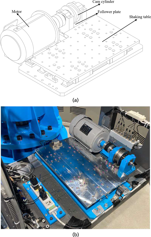
(a) Newly developed shaking table device. (b) Shaking table mounted on the arm of the TCU Mark III geotechnical centrifuge facility
(a) Newly developed shaking table device. (b) Shaking table mounted on the arm of the TCU Mark III geotechnical centrifuge facility
Specifications of the cylindrical cam shake table
| Shaking table size | 500 mm × 270 mm |
|---|---|
| Total mass of the shaking table | 71 kg |
| Maximum achievable shaking table displacement | 0–5 mm |
| Earthquake waveform | Limited to sinusoidal waveform |
| Maximum centrifugal acceleration | 50g |
| Maximum sample weight | 50 kg |
| Electrical motor | 0.75 KW × 200 V |
3.1 Mechanical design and control system details of the cylindrical cam shake table
It is important that the shaking table be easy to mount and unmount, depending on the desired experiment (i.e., a static or dynamic test), and is isolated from the centrifuge machine. Ease of use, initial cost of construction, huge lifetime maintenance costs, and shaking control (to ensure repeatability of the dynamic centrifuge experiments) were the main concerns in the design phase of the shaker. The earthquake excitation is driven by a cylindrical cam rotation mechanism with two waves per rotation. An electric motor with a voltage of 200 V and a capacity of 0.75 kW is attached to the shaking table platform as shown in Figure 6. The arrangement includes a follower plate that rested below the surface of the cam cylinder in a direction perpendicular to the rotational axis of the shaft, as shown in Figure 6(a). The follower plate was linked to the main shaking-table platform using bolt connection.
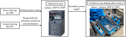
Power and control-slip rings were used to establish the connection between the shaking table actuator and the geotechnical centrifuge. As stated in the previous section, the power slip rings with an AC100V power supply terminal block include three terminals that are only compatible with a voltage of 100 V. For this purpose, an onboard inverter was mounted on the centrifuge arm to convert the primary power supply to secondary power supply, delivering a voltage of 200 V to the motor mounted on the shaking table platform. This assembly is presented in Figure 7. To drive the shaking table actuator, the second analogue voltage channel of the control-slip ring is used to apply a preset voltage magnitude in the range of DC 0–5 V voltage to the electrical motor (i.e., the shaker does not need any commanded input motion). To supply the shaking table with a sinusoidal earthquake excitation, an automatic switching function is used by making use of the three contact channels (terminals 5–6, terminals 7–8, and terminals 9–10) of the control-slip rings. The first channel (terminals 5–6) is used to establish contact between the actuator system mounted on the centrifuge platform (such as a rainfall actuator with different nozzles, a load cell, or a cone penetration testing (CPT) machine) and a centrifuge with a power supply of 100 V. The second channel (terminals 7–8) is used to measure the triggered signals (e.g., acceleration response, pore pressure response, or strain response) from various instruments installed within the model container. The third channel (terminals 9–10) is used to excite the shake table with a predetermined sinusoidal signal (i.e., frequency and maximum acceleration magnitude, which depends on the applied voltage and payload mass).
3.2 Working mechanism and operational details of the cylindrical cam shake table
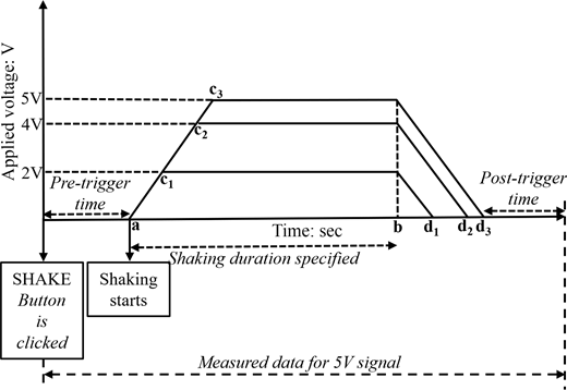
Initially, the shaking duration, the pre-trigger delay, and the post-trigger delay need to be specified. The toggle switch on the second channel (terminals 7–8) needs to be turned on for the purpose of data measurement from the mounted instrumentations. To drive the mechanical shaker with the desired earthquake characteristics, one needs to set the required voltage at the second analogue output channel. The maximum voltage that can be applied to the electric motor is 5 V. For the shaking table tests, the toggle switch on the third channel (terminals 9–10) of the control-slip ring also needs to be turned on. The shaking control is managed through the automatic switching operation. The desired measurement duration for the various installed instrumentation is set in the automatic switching process. Furthermore, the duration of shaking is programmed through the automatic switching operation. The cylindrical cam mechanism and the automatic switching is activated once the shake button is clicked. The rotational speed of the cylindrical cam depends on the applied voltage and inverter frequency. Table 3 presents the achieved rotational speed of the electrical motor mounted on the shake table (in rpm) and the achieved excitation frequency of the sine waveform (in Hz) depending on the applied DC voltage (V) and setup inverter frequency (Hz). As observed from Table 3, the achieved motor speed and the excitation frequency increases with the increase in the applied voltage and setup inverter frequency.
Motor speed achieved as a function of the DC voltage applied
| Applied DC voltage: V | Setup inverter frequency: Hz | Motor rotation speed: rpm | Excitation frequency: Hz |
|---|---|---|---|
| 0.88 | 10 | 200 | 7 |
| 1.74 | 20 | 400 | 13 |
| 2.60 | 30 | 600 | 20 |
| 3.46 | 40 | 800 | 27 |
| 4.34 | 50 | 1000 | 33 |
The rotational motion of the cylindrical cam is transformed into a linear motion of the follower plate as the cylindrical cam strikes the plate several times, depending on the applied frequency and duration of the motion. The rotation of the cylindrical cam shaft is non-uniform to allow the follower plate to move back and forth. The linear motion of the follower plate drives the shaking table and eventually leads to earthquake excitation in both directions along the horizontal axis. However, the cylindrical cam takes certain time to achieve a constant rotation speed following a gradual increase in the rotation rate. This gives rise to the initial ramp in the seismic signal. This mechanism is portrayed in Figure 8. Notably, the slope of the initial ramp is same irrespective of the applied voltage magnitude. Once a constant rotation speed is achieved by the cylindrical cam, sinusoidal cycles with nearly similar peak acceleration levels are fired. The duration including the initial ramp and time regime with the application of constant acceleration cycles (as an example time instance ‘a’ to ‘b’ in Figure 8) is the shaking duration specified in the automatic switching function. Following this, the cylindrical cam takes certain time to come to a standstill position with a gradual decrease in the rotation rate. This gives rise to the descending ramp in the seismic signal as presented in Figure 8. The slope of the descending ramp is also same as the slope of the ascending ramp. As an example, if a 5 V DC voltage is applied, the shaking will commence following the initial pre-trigger time. The duration of the ascending ramp is a–c3. Following this, c3–b represents duration with the application of constant sinusoids. This will be followed by the descending ramp with a duration of b–d3. The measured data will also include the post-trigger time to record the post-shaking mechanics such as consolidation process with the dissipation of excess pore pressures.
As this is a mechanical shaker, the seismic signal is limited to a simple sinusoidal waveform and the models cannot be excited with multi-frequency motion. Schofield and Steedman (1992) have emphasised the complexity associated with using previously recorded realistic earthquakes in identifying key aspects of soil–structure interactions and that the simplistic sinusoidal waveform may be used to comprehensively investigate the fundamental mechanisms and influence of key control parameters in a given problem. This has led researchers at several geotechnical centrifuge facilities to use a sinusoidal waveform, despite having access to a servo-hydraulic shaker (e.g., Espanol-Espinel et al., 2024; Fusco et al., 2023; Garala and Madabhushi, 2021; Saade et al., 2023; Xu et al., 2022). Furthermore, the ramped sinusoidal motion is a standard motion adopted for the international collaborative research framework of Liquefaction Experiments and Analysis Projects, which includes several centrifuge facilities across Europe, Asia, and North America, although all facilities are equipped with servo-hydraulic shakers (Manzari et al., 2018; Tobita et al., 2022). Moreover, Schofield and Steedman (1992) emphasised that an ‘ideal’ earthquake does not necessarily reflect the realistic situation on site, as the characteristics of the previously recorded motions are unlikely to match those of the potential future earthquake. Therefore, a simplistic sinusoidal motion can be effectively used to determine the dynamic response of the geosystem.
3.3 Performance of the cylindrical cam shake table
The performance of the developed novel cylindrical cam mechanical shake table was assessed by a series of centrifuge experiments conducted on a dry sand model. Table 4 lists a series of centrifuge proof experiments performed using a rigid box container at two different payload masses of 36 and 50 kg at the model scale (with soil mass of 11.6 and 25.6 kg, respectively). Moreover, the tests were conducted at two different centrifugal accelerations of 20g and 50g, respectively, with sinusoidal waves fired under different applied voltages, as shown in Table 4. A three-dimensional accelerometer was installed at the bottom of the rigid box container to measure the acceleration signal. The results are explained in the model scale unless otherwise stated.
Different series of centrifuge experiments
| With a mass of 36 kg | With a mass of 50 kg | ||
|---|---|---|---|
| Applied voltage at a centrifugal acceleration of 20g: V | Applied voltage at a centrifugal acceleration of 50g: V | Applied voltage at a centrifugal acceleration of 20g: V | Applied voltage at a centrifugal acceleration of 50g: V |
| 0.88 | 0.88 | 0.88 | 0.88 |
| 1.74 | 1.74 | 1.74 | 1.74 |
| 2.60 | 2.60 | 2.60 | 2.60 |
| 2.80 | 2.80 | 2.80 | 2.80 |
| 2.90 | 2.90 | — | — |
| 3.00 | 3.00 | — | — |
3.3.1 Response of the cylindrical cam shake table with a model mass of 36 kg at a centrifugal acceleration of 20g and 50g
Figures 9 and 10 present the measured acceleration responses under different values of the applied voltage for a series of centrifuge experiments performed with a model mass of 36 kg and centrifugal acceleration of 20g and 50g. As expected, the achieved maximum acceleration amplitude (amax) or peak ground acceleration (PGA) achieved increases with the increase in the magnitude of the applied voltage. Importantly, Figures 9 and 10 show that the measured signal at a given voltage value is comparable to a nearly equal PGA achieved at centrifugal accelerations of 20g and 50g. Furthermore, the developed mechanical shaker was able to realise different levels of shaking (i.e., non-destructive and destructive) depending on the purpose of the experiment. This can be corroborated with the measured peak acceleration of 0.8g (0.04g in the prototype scale) when applying a 0.88 V signal at 20g, which represents a weak non-destructive shaking up to an achieved motion with 12 cycles hovering at a peak acceleration of 12.8g (0.64g at the prototype scale) owing to the application of a 3 V signal, which can be considered a strong destructive earthquake.
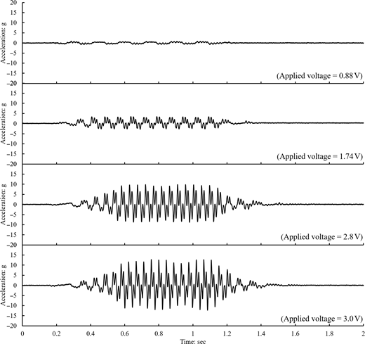
Response of the cylindrical cam shake table at different values of applied voltage for a series of centrifuge experiments with a model mass of 36 kg at a centrifugal acceleration of 20g
Response of the cylindrical cam shake table at different values of applied voltage for a series of centrifuge experiments with a model mass of 36 kg at a centrifugal acceleration of 20g
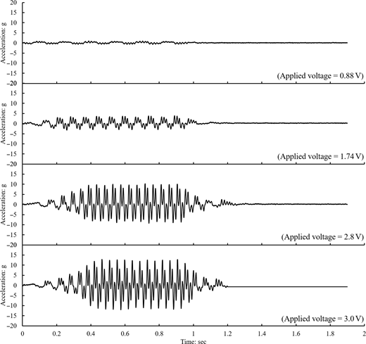
Response of the cylindrical cam shake table at different values of applied voltage for a series of centrifuge experiments with a model mass of 36 kg at a centrifugal acceleration of 50g
Response of the cylindrical cam shake table at different values of applied voltage for a series of centrifuge experiments with a model mass of 36 kg at a centrifugal acceleration of 50g
To investigate the frequency content and further assess the repeatability of the obtained sinusoidal motions (across the two different centrifugal accelerations) in the Fast Fourier Transform (FFT domain), Figure 11 shows the Fourier spectrum response of the measured signals under varying voltage magnitudes. As the applied voltage was increased, the magnitude of the excitation frequency increased (i.e., the number of cycles increased significantly) along with the peak acceleration amplitude (PGA). Furthermore, the repeatability of the different input ground motions under two different centrifugal accelerations of 20g and 50g was excellent, with a nearly similar peak Fourier amplitude at the primary excitation frequency. As shown in Figure 11, the obtained signal has two main frequencies during the predominant duration of the motion: an excitation frequency with a larger Fourier response peak, followed by a smaller Fourier peak at a higher frequency. This is clearly visible when a relatively strong signal (i.e., 2.8 and 3.0 V) is applied. However, the Fourier amplitude at the predominant excitation frequency was considerably larger than the measured Fourier amplitude at higher frequencies. In particular, at higher frequencies, a relatively larger variation in Fourier amplitude was observed between the two signals at different centrifugal accelerations under the same applied voltage magnitude (especially at larger voltage values).
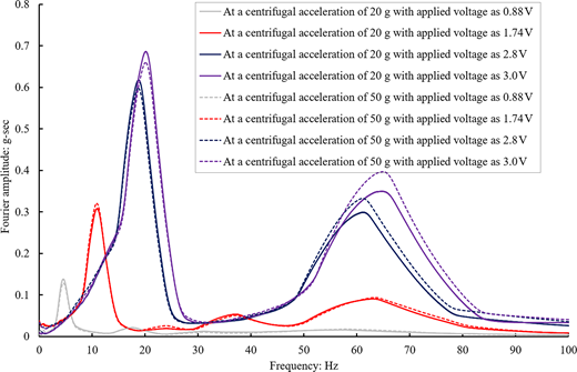
Fourier spectrum of the input motions obtained for the series of centrifuge experiments with a model mass of 36 kg subjected to different centrifugal accelerations and applied voltages
Fourier spectrum of the input motions obtained for the series of centrifuge experiments with a model mass of 36 kg subjected to different centrifugal accelerations and applied voltages
3.3.2 Response of the cylindrical cam shake table with a model mass of 50 kg at a centrifugal acceleration of 20g and 50g
Figures 12 and 13 present the measured acceleration responses under different applied voltages for a series of centrifuge experiments with a model mass of 50 kg and a centrifugal acceleration of 20g and 50g, respectively. When the model mass was increased to 50 kg, the measured maximum acceleration amplitude decreased slightly. For example, the maximum acceleration amplitude for the experiment at a centrifugal acceleration of 20g and a 2.8 V signal was 8.25g with a payload mass of 50 kg, which represents a reduction of almost 20% compared with the experiment when the payload mass was 36 kg. Similar to the model mass of 36 kg, the capability of the shaker is shown with a similar measured ramped sine waveform pattern under the centrifugal accelerations of 20g and 50g at different voltage values. In addition, Figure 14 shows similar characteristics of the shaker at a payload of 50 kg as at a payload of 36 kg (i.e., an increase in the excitation frequency with an increase in the applied voltage and a similar excitation frequency magnitude at the two different centrifugal accelerations for the four signals). Of note is the significant reduction in FFT amplitude in a higher frequency range of 55–65 Hz with an increased payload mass of 50 kg (Figure 14) compared with a payload mass of 36 kg (Figure 11).
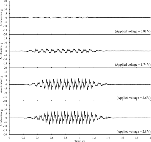
Response of the cylindrical cam shake table at different values of applied voltage for a series of centrifuge experiments with a model mass of 50 kg at a centrifugal acceleration of 20g
Response of the cylindrical cam shake table at different values of applied voltage for a series of centrifuge experiments with a model mass of 50 kg at a centrifugal acceleration of 20g

Response of the cylindrical cam shake table at different values of applied voltage for a series of centrifuge experiments with a model mass of 50 kg at a centrifugal acceleration of 50g
Response of the cylindrical cam shake table at different values of applied voltage for a series of centrifuge experiments with a model mass of 50 kg at a centrifugal acceleration of 50g
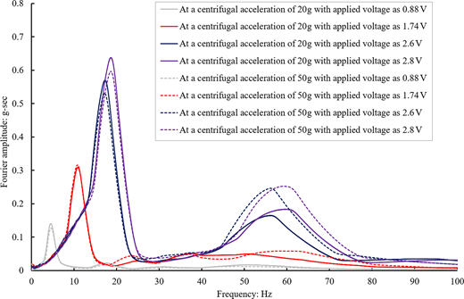
Fourier spectrum of the input motions obtained for the series of centrifuge experiments with a model mass of 50 kg subjected to different centrifugal accelerations and applied voltages
Fourier spectrum of the input motions obtained for the series of centrifuge experiments with a model mass of 50 kg subjected to different centrifugal accelerations and applied voltages
3.4 Relationship between the different parameters for the cylindrical cam shake table
In contrast to servo-hydraulic shake tables, which usually require user-commanded input displacement or acceleration time history data, the developed mechanical cylindrical cam shaker depends only on the applied voltage to impart the acceleration time history signal to the mounted payload. Although the duration of the shaking can be controlled by the automatic switching function, it cannot determine the number of cycles or the maximum acceleration amplitude. The relationships between the characteristics of the earthquake (i.e., the excitation frequency and the maximum amplitude of acceleration), the applied voltage, and the payload model mass were developed based on the series of centrifuge experiments described in Section 3.3. The required voltage to drive the shaker to achieve the desired peak acceleration and excitation frequency can be determined using the following steps.
- ▪
Step 1: Based on a number of experiments, the maximum capacity of the centrifuge device with the developed shaking table was determined to be 520 g-kg (where g represents the maximum acceleration amplitude of the shaker). Based on this limit, the relationship between the maximum acceleration amplitude (amax) and model mass shown in Figure 15(a) was developed, which shows that the maximum acceleration amplitude increases as the payload mass decreases. Figure 15(a) can be used to determine the maximum possible acceleration amplitude that can be applied to a specific payload mass. For example, with a payload mass of 50 kg, the maximum possible acceleration amplitude on a model scale is 10.4g. This would correspond to 0.52g in the prototype scale under the operational centrifugal acceleration of 20g or 0.21g under the operational centrifugal acceleration of 50g.
- ▪
Step 2: Figure 15(b) shows the relationship between the excitation frequency and the maximum acceleration amplitude under different centrifugal accelerations and payload mass. As seen from Figure 15(b), nearly an identical relationship is obtained at centrifugal accelerations of 20g and 50g under the payload mass of 36 kg. With the increase in payload mass to 50 kg, slight variations are observed in the relationship under different centrifugal accelerations; however, the overall trend is the same. As an example, the relationship between the excitation frequency and maximum acceleration amplitude under the centrifugal acceleration of 50g and payload mass of 36 kg can be suitably defined in terms of a second-order polynomial function with an R2 correlation factor of 1 as
where f is the excitation frequency and amax is the maximum acceleration amplitude. Based on this established relationship, the excitation frequency can be determined using a known amax value. For example, under the amax value of 10.4g, the excitation frequency is evaluated as 18.9 Hz (model scale).1 - ▪
Step 3: Figures 15(c) and 15(d) show the relationship between the achieved maximum acceleration amplitude with the applied voltage and the achieved excitation frequency with the applied voltage, respectively. A slight discrepancy is observed in the relationship among the maximum acceleration amplitude and the applied voltage at different centrifuge accelerations of 20g and 50g under the payload mass of 50 kg. On the other hand, an identical linear relationship is observed between the excitation frequency and the applied voltage irrespective of the applied centrifugal acceleration and the payload mass. This indicates that there might be slight variations in the achieved maximum acceleration amplitude depending on the operating centrifugal acceleration and mounted payload. However, the achieved excitation frequency in the model scale is independent of the operating centrifugal acceleration and payload mass. As an example, the voltage required to drive the mechanical shaker to meet the desired maximum acceleration amplitude and the excitation frequency for a payload mass of 36 kg under a centrifugal acceleration of 50g can be determined in terms of a second-order polynomial function and a linear function with an R2 correlation factor of 1 as per Equations 2 and 3, respectively.
2where V is the applied voltage. To achieve a maximum acceleration of 10.4g at an excitation frequency of 18.9 Hz, the shaker needs to be driven with a voltage amplitude of 2.8 V.3
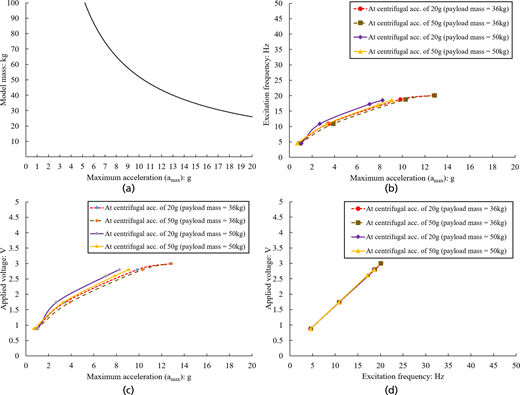
(a) Relationship between the maximum acceleration amplitude and the model mass. (b) Relationship between the applied voltage and the maximum acceleration amplitude. (c) Relationship between the maximum acceleration amplitude and the excitation frequency. (d) Relationship between the applied voltage and the excitation frequency
(a) Relationship between the maximum acceleration amplitude and the model mass. (b) Relationship between the applied voltage and the maximum acceleration amplitude. (c) Relationship between the maximum acceleration amplitude and the excitation frequency. (d) Relationship between the applied voltage and the excitation frequency
3.5 Comparison of the seismic response of the cylindrical cam shake table with other servo-hydraulic type shake tables
A comparative analysis was conducted to assess the mechanical performance of the cylindrical cam shake table in relation to the other servo-hydraulic shaking table devices installed on beam-type geotechnical centrifuges. Figure 16 shows a comparison among the dynamic centrifuges with a servo-hydraulic actuator (at Kyoto University, JNIOSH and Nippon Koei Co. Ltd.) and the Mark-III centrifuge at TCU with a cylindrical cam in terms of the achieved input motion in a similar ramped sinusoidal waveform pattern (i.e., initial ramp followed by an intermediate phase with the application of constant cycles and a descending ramp) at an excitation frequency of 1 Hz. Notably, a similar slight variation in the achieved peak acceleration amplitude could be observed from the response of servo-hydraulic shakers and the cylindrical cam at application of some of the cycles during the intermediate phase. Importantly, the cylindrical cam shaker contained a high-frequency FFT component at 3 Hz, similar to the high-frequency FFT amplitude manifested by the servo-hydraulic shakers at Kyoto University and JNIOSH (approximately three times the excitation frequency at 3 Hz). Zhou et al. (2020) conducted several centrifuge experiments and noticed a similar response for the newly developed servo-hydraulic actuator installed on the geotechnical centrifuge facility at Zhejiang University. They suggested that the interaction of the system could be a possible cause of the high-frequency FFT component and should be considered an inherent characteristic of the shaking table (Cao et al., 2024). However, the extent of high-frequency FFT spectral magnitude in the case of servo-hydraulic actuator depend on the particular custom-made earthquake simulator and may be nullified depending on the shaker (as an example, shaker at the Nippon Koei Co. Ltd. depicted in Figure 16(c)). This aspect of the variations in the high-frequency FFT component was also highlighted by Kutter et al. (2018) by comparing the achieved input motions among the different centrifuge facilities with different custom-made servo-hydraulic shakers that participated in the LEAP-GWU-2015 study.
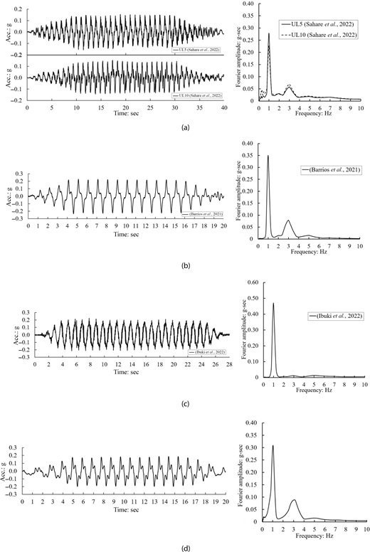
Input acceleration data for a similar ramped sinusoidal waveform pattern. (a) Servo-hydraulic shaker installed at the Disaster Prevention Research Institute, Kyoto University (data from Sahare et al., 2022). (b) Servo-hydraulic shaker installed at the Japanese Institute of Occupational Safety and Health, JNIOSH (data from Barrios et al., 2021). (c) Servo-hydraulic shaker installed at the Nippon Koei Co. Ltd. (data from Ibuki et al., 2022). (d) Mechanical cylindrical cam shaker installed at the TCU
Input acceleration data for a similar ramped sinusoidal waveform pattern. (a) Servo-hydraulic shaker installed at the Disaster Prevention Research Institute, Kyoto University (data from Sahare et al., 2022). (b) Servo-hydraulic shaker installed at the Japanese Institute of Occupational Safety and Health, JNIOSH (data from Barrios et al., 2021). (c) Servo-hydraulic shaker installed at the Nippon Koei Co. Ltd. (data from Ibuki et al., 2022). (d) Mechanical cylindrical cam shaker installed at the TCU
According to Figure 16, it can be inferred that the newly designed cylindrical cam shaker may exhibit similar earthquake characteristics to the motion achieved by the servo-hydraulic shake table actuators in the time and frequency domain (depending on the particular custom-made servo-hydraulic actuator). However, servo-hydraulic shake tables have an obvious limitation with regard to the shaking control and repeatability of input motions. The next section highlights the potential of the newly developed cylindrical cam shake table with this regard.
4. Shaking control of the cylindrical cam shake table: investigating the aspect of repeatability
The shaking control features of the newly developed cylindrical cam shake table were investigated through a series of earthquake excitations applied to the model example shown in Figure 17. A rigid container was used to study the seismic deformation mechanism of a dry-masonry retaining wall system. The model was subjected to a series of four earthquake excitations (ramped sinusoidal waveforms) under a similar voltage value of 3.76 V at a centrifugal acceleration of 30g. A three-dimensional accelerometer was mounted at the base of the rigid model container to measure the input motions. The results are presented in model scale.
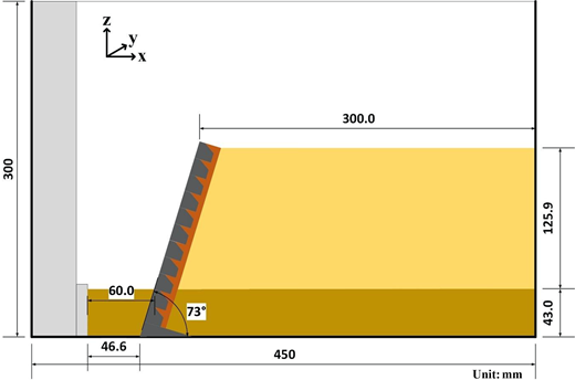
Centrifuge model to investigate the seismic deformation mechanism of a dry masonry retaining wall
Centrifuge model to investigate the seismic deformation mechanism of a dry masonry retaining wall
Figure 18 shows the acceleration time history data for the four achieved input motions (shaking events 1, 2, 3, and 4). In addition, Figure 18 also shows the Arias intensity time history data. The Arias intensity is an effective measure of the combined effect of PGA and shaking duration. Each cycle of the entire earthquake overlapped perfectly, as shown in Figure 18, for shaking events 1 and 2, along with shaking events 3 and 4. The measured PGA’s during shaking events 1 and 2 were 14.5g and 14.8g, which is a tiny difference of 2%. The measured PGA’s during shaking events 3 and 4 were 15.1g and 14.3g, which is a difference of 5%. Figure 18(b) shows slight differences only for the ninth cycle (just after 0.6 s), and the other cycles overlap perfectly between events 3 and 4. The evolution of Arias intensity with time shows excellent agreement between the different seismic motions.
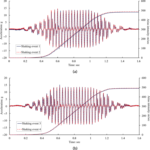
Achieved input acceleration time history at the bottom of rigid model container. (a) For shaking events 1 and 2. (b) For shaking events 3 and 4
Achieved input acceleration time history at the bottom of rigid model container. (a) For shaking events 1 and 2. (b) For shaking events 3 and 4
The spectral acceleration depicted in Figure 19 emphasises the significant capability of the shaker to generate a comparable peak spectral acceleration at the excitation frequency of the motion during the four shaking episodes. An analysis of the acceleration response spectra revealed notable discrepancies in the input base motions produced by the different servo-hydraulic actuators installed at various centrifuge facilities involved in the LEAP-GWU-2015 project, in comparison to the specified motion (Kutter et al., 2018). The newly installed servo-hydraulic shaker at Zhejiang University had similar problems in fine tuning the achieved and target acceleration response spectra (especially in the case of ramped sine waves), as reported by Zhou et al. (2020).
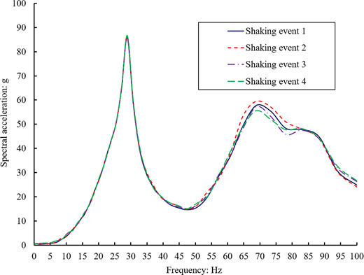
Overall, Figures 18 and 19 show the applicability of the newly developed cylindrical cam shaker in terms of the repeatability of the input ground motions compared with the servo-hydraulic shaking table actuators.
5. Concluding remarks
In this paper, a newly developed Mark III beam-type geotechnical centrifuge facility and a novel cylindrical cam mechanical shaking table actuator at TCU are presented.
- ▪
This paper initially describes the mechanical design and operational details of the new beam type geotechnical centrifuge machine. The features of the various installed components and data acquisition systems, such as electrical slip rings, are presented.
- ▪
A detailed discussion on the development, mechanical operation, and shaking mechanism of the novel cylindrical cam shaker is presented. Our main objective was to develop a shaker that is significantly cheaper (both in terms of initial cost and maintenance cost), whose operating principles are easy to understand and can simply apply earthquake excitations by converting rotational motion into linear motion by utilising the cylindrical cam mechanism.
- ▪
The performance of the cylindrical cam shaker was systematically assessed through a series of centrifuge experiments conducted on a dry sand model at different centrifugal accelerations and payload masses using a rigid box container. As the applied voltage increases, the achieved PGA and the excitation frequency also increases irrespective of the centrifugal acceleration and payload mass. To determine the magnitude of the voltage required to drive the shake table to achieve a target PGA and excitation frequency, a step-by-step procedure was developed by establishing the relationship between the PGA, excitation frequency, applied voltage, and payload mass.
- ▪
A comparison of the cylindrical cam shaker with servo-hydraulic shaking table actuator revealed the presence of a similar high-frequency FFT amplitude in the Fourier spectrum (occurring at three times the excitation frequency) and slight variation in the peak acceleration amplitude during the application of constant cycles.
- ▪
To investigate the seismic control of the developed shaker, a series of dynamic centrifuge experiments were conducted on an example model comprising dry masonry retaining wall system. The model was subjected to four earthquakes by applying a similar voltage value of 3.76 V under a centrifugal acceleration of 30g. The results demonstrated the great potential of the shaker in terms of repeatability of all cycles in seismic events 1, 2, 3, and 4, which overlapped perfectly.
- ▪
The positive points of the novel cylindrical cam shaker include its simple operational mechanism, cheap cost of construction, and excellent shaking control in terms of repeatability of centrifuge experiments. The limitations include the incapability of the shaker to generate a wider range of sine waveforms as it can only generate a unique sinusoidal waveform pattern presented in the paper. Furthermore, since the shaker is a mechanical device, it cannot generate earthquake excitations with multiple frequency components.
Acknowledgements
The TCU Mark III geotechnical centrifuge facility and the cylindrical cam mechanical shaking table actuator were developed with the support of Tokyo City University under the introduction of ‘Large Research Equipment and Facilities’ for the development of research infrastructure. The authors are also thankful to Dr. Izawa from Railway Technical Research Institute, Tokyo, Japan and Dr. Uemura from Nippon Koei, Co., Ltd., Ibaraki, Japan for providing the input waveforms.

