


Conventional high-speed railways (HSR) subgrade design methods remain constrained by platform-dependent drafting systems, leading to data interaction hindrances and redundant design processes. This study strives to develop a digital earthwork design methodology that enhances design while reducing collaborative expenses.
A novel digital subgrade design approach, utilizing sophisticated analysis and modeling tools customized for different subgrade elements, is put forward in this study. The methodology incorporates the following essential steps: (1) the advancement of digital analysis and modeling techniques for diverse subgrade components, including surfaces, filling, slopes, retaining structures, and foundation treatments; (2) the formulation of a digital design principle repository incorporating various slope protection combinations; (3) the establishment of a comprehensive digital design framework and process for subgrade cross-sections; and (4) the development and implementation of an open-source digital design system.
The proposed method liberates subgrade design from the constraints of conventional drawing platforms, elevating efficiency, intelligence, and flexibility. The open software architecture and code have achieved over 60% efficiency gains in design workflows during its deployment on three major high-speed rail projects: the Baotou-Yinchuan HSR corridor, Shenyang-Baihe HSR network, and Weifang-Yantai HSR system.
This paper introduces an innovative digital design methodology that enables modular and parametric design for railway subgrade sections. The proposed approach provides a digital base for the intelligent design and maintenance of the next-generation high-speed railway.
1. Introduction
Railway subgrade plays a pivotal role in providing track support, distributing loads, and ensuring the seamless operation of trains (Ye et al., 2021, 2022; Roshan et al., 2022; Fattah, Majeed, & Joni, 2024). The quality of its design directly impacts the safety, stability, and longevity of railway lines (Chen, Chen, & Wang, 2014; Wang, Wei, Yang, Fei, & Guo, 2024), while the diverse terrain and geological conditions induce a heavy design workload and complex design tasks (Lu, Liu, Liu, & Liu, 2019; Li & Li, 2023). Therefore, digital design, integrating geometric modeling, performance analysis, cost estimation, and construction simulation, has emerged as a powerful tool to address the above challenges (Lu et al., 2019).
Early digital subgrade design primarily relied on CAD platforms in the form of plugins and tools (Li, Xue, Shao, Zhu, & Liu, 2023; Zhang, Liu, & Yang, 2023). For example, Bai (2021) utilized the CAD’s ARX secondary development technology to automate excavation area calculation in railway cross-section design. Based on, NET for secondary development of Auto CAD and Excel, Lu and Wang (2020) implement auxiliary design technologies for subgrade slope protection. These advancements have significantly enhanced the efficiency of geometric models, sectional design, and earthwork volume calculations.
Recently, Building Information Modeling (BIM) technology has revolutionized the digital design of railway subgrades by providing a comprehensive, three-dimensional model that incorporates geometric, physical, and functional information (Vignali et al., 2021; Cao, 2022; Cao, Lan, & Li, 2023; Wang, 2021; Kodikara, Sounthararajah, & Chen, 2024). Alqatawna, Sánchez-Cambronero, Gallego, and Rivas (2023) applied BIM to designing a high-speed railway (HSR) line in Spain, emphasizing its benefits in optimizing the design process, improving stakeholder collaboration, and facilitating lifecycle management. Similarly, Pu et al. (2022) extended the Industrial Foundation Classes (IFC) standard for BIM to model multi-component subgrades in railway stations, addressing the complexities associated with these structures. Fan et al. (2024) introduced a microprism-based layered BIM modeling method to tackle the complexities in railway station subgrades. Additionally, BIM facilitates multi-disciplinary collaborative design, enabling seamless integration of subgrade design with other railway engineering disciplines.
Despite the above advancements in the digital design of railway subgrades, existing methodologies are hindered by notable limitations. Chief among these constraints is the reliance on specific drawing platforms like AutoCAD and Revit, which impede seamless data interaction and induce repetitive design—particularly in extensive batch projects (Li et al., 2023; Zhang et al., 2023; Bai, 2021). Moreover, inconsistent data formats and standards among different platforms add another layer of complexity to collaborative design endeavors, resulting in heightened costs and inefficiencies (Ma, 2021).
This study aims to address the efficiency limitations inherent in conventional subgrade design methodologies by introducing a novel digital design method for the railway subgrade section. To start with, a digital storage model and analysis algorithm for geological mapping are established. Subsequently, a digital modeling method is proposed for the diverse structures within railway subgrades. Moreover, the subgrade sections are assembled under various working conditions according to digital design principles. Finally, a corresponding digital system is created and deployed, with validation through practical implementation in HSR projects.
2. Digital analysis and geometric modeling of subgrade
The subgrade design is based on alignment data, geological conditions, and section surveys. According to the design principles, structures such as the subgrade surface, filling materials, drainage systems, slopes, retaining structures, and foundation treatments are organically assembled. This section introduces the digital analysis and modeling methods for geological sections and subgrade structures.
2.1 Digital model of geological section
Building on the method proposed by Bai (2021), this study utilizes a technique to transform ground and stratum boundaries into point sets, as depicted in Figure 1. This set employs the line’s center as the reference point of the local coordinates, with the stratum boundary’s upper and lower segments containing stratum information attributes, as demonstrated in Table 1.
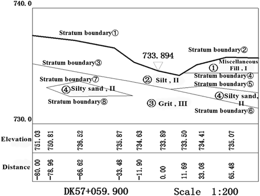
Local coordinate point sets of the stratum boundaries in the geological section
| Stratum number | Upper geological | Lower geological | Local coordinate point sets {xi, yi} |
|---|---|---|---|
| Stratum boundary① | – | Silt, II | (−43.71, 12.55), (−26.00, 10.39) |
| Stratum boundary② | – | Miscellaneous Fill, I | (8.11, −0.59), (12.05, 1.98) |
| Stratum boundary③ | Silt, II | Grit, III | (−43.71, 12.55), (−26.00, 10.39) |
| Stratum boundary④ | Miscellaneous Fill, I | Silt, II | (8.11, −0.59), (41.35, −0.59) |
| Stratum boundary⑤ | Silt, II | Silty Sand, II | (3.96, −6.25), (4.33, −6.33) |
| Stratum boundary⑥ | Silty Sand, II | Grit, III | (3.96, −6.25), (14.14, −5.06) |
| Stratum boundary⑦ | Grit, III | Silty Sand, II | (−34.86, −10.07), (−24.64, −7.87) |
| Stratum boundary⑧ | Silty Sand, II | Grit, III | (−34.86, −10.07), (−27.33, −13.23) |
Source(s): Authors’ own work
2.2 Surface and type of subgrade
The subgrade surface can be digitized using the following procedure: The primary design parameters include the surface shape, shoulder elevation, subgrade width, and track distance. The surface shape is divided into triangular and trapezoidal, according to the ballasted or ballastless tracks. The shoulder elevation and curve widening are calculated based on the longitudinal section and superstructure data. The width of the track slab is determined according to the track slab type. An example of surface parameters is shown in Table 2.
Example of subgrade surface parameters
| Railway type | Shape | Shoulder height | Half width | Curve widening | Drainage slope | Design baseline | Slab width | ||||
|---|---|---|---|---|---|---|---|---|---|---|---|
| Left | Right | Left | Right | Left | Right | Left | Right | ||||
| Ballasted HSR | Triangle | Hl | Hr | 4.3 | 4.3 | Wl | Wr | 4% | 4% | Left line | 0.0 |
| Ballastless HSR | Trapezoid | Hl | Hr | 4.3 | 4.3 | Wl | Wr | 4% | 4% | Left line | PLW |
Source(s): Authors’ own work
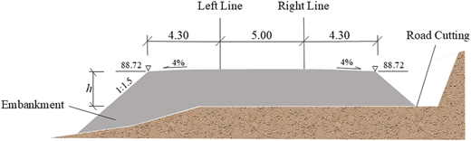
The subgrade is categorized into two forms: embankment and cutting, based on the spatial relationship between the subgrade surface and the ground line, as shown in Figure 2. In Figure 2, the connection between the endpoints of the subgrade surface on both sides and the side ditch forms the subgrade slope line. If the bottom endpoint of the subgrade slope is above the ground line, it is classified as an embankment; conversely, if it lies below, it is classified as a cutting. In Figure 2, h represents the vertical height between the shoulder of the embankment-like cutting and the platform inside the side ditch. When h = 0, it indicates a standard cutting; when h > 0, it indicates an embankment-like cutting. Notably, in the high-speed railway cutting designs, a cutting with an embankment-like design is adopted to enhance subgrade drainage capacity and prevent water accumulation during heavy rainfall, incorporating a slope between the shoulder and the side ditch.
2.3 Series protection combinations
Once the subgrade types are determined, the control points on both sides serve as the basis for connecting the series-type protection combinations. The protection combinations including side ditches, slopes, and retaining structures are demonstrated in Appendix A Common retaining measures include gravity and pile sheet walls, with the typical protection combination illustrated in Table 3.
Side ditch
Typical slope protection combinations
| Subgrade form | Slope protection type | Facility 1 | Facility 2 | Facility 3 | Endpoint | |||
|---|---|---|---|---|---|---|---|---|
| Name | Series points | Name | Series points | Name | Series points | |||
| Embankment | Slope | Slope | Shoulder | – | – | – | – | Ground Intersection |
| Embankment | Slope + Gravity Retaining Wall | Slope | Shoulder | Gravity Retaining Wall | Controlling Value | – | – | – |
| Embankment | Slope + Sheet-Pile Wall | Slope | Shoulder | Sheet-Pile Wall | Controlling Value | – | – | – |
| Cutting | Slope | Side Ditch | Shoulder | Slope | Side Ditch Platform | – | – | Ground Intersection |
| Cutting | Slope + Gravity Retaining Wall | Side Ditch | Shoulder | Gravity Retaining Wall | Side Ditch Platform | Slope | Coping | Ground Intersection |
| Cutting | Slope + Sheet-Pile Wall | Side Ditch | Shoulder | Sheet-Pile Wall | Side Ditch Platform | Slope | Coping | Ground Intersection |
Source(s): Authors’ own work
The side ditch is the first-level measure connecting the subgrade surface of the cutting and serves as a drainage channel. The design parameters for side ditches are provided in Table B1. The control point of the side ditch represents the height of the embankment-like cutting slope. A value of 0.0 indicates a standard cutting, while a value exceeding 0.0 indicates an embankment-like cutting.
Slope
The embankment slope and cutting slope are connected to the subgrade surface and side ditch or retaining structure, with the control point of the shoulder and superior facility (side ditch platform, gravity retaining wall, or the top platform of the sheet pile wall). Meanwhile, the slope may consist of multiple levels, and each level includes the following design parameters: slope height, slope gradient, protection type, platform width, and platform gradient, with typical parameters shown in Table B2.
Retaining structures
This paper introduces parametric models for two commonly used retaining structures in railway subgrades: gravity and sheet pile walls. The parametric models for other retaining structures can be developed using similar methods outlined in this study. The design parameters for gravity walls are shown in Table B3, while those for sheet pile walls can be found in Table B4. Typical protection combinations for embankments and cuttings are illustrated in Figure B1.
2.4 Filling line
Filling is a crucial component of the subgrade beneath the subgrade surface. The vertical position of the filling is determined by the layer sequence and thickness. Concurrently, its horizontal boundaries are defined by the boundary lines of the embankment slope and retaining structure combination, as well as the cutting slope and retaining structure combination. The subgrade may consist of multiple layers of filling and their design parameters are shown in Table B5.
Notably, “Replacement” refers to the scenario where the filling layer is located below ground level, necessitating upward excavation at a replacement angle followed by backfilling using the same material. The geometric model of the filling parameters is shown in Figure B1.
2.5 Interactive design lines
The design requirements in some special geological conditions cannot be fulfilled by parametric measures, e.g. the poor slope strata steep slope needing excavation or excavation. Therefore, hand-drawn lines are introduced to convey designers’ intent, namely interactive design lines. Interactive design lines encompass step lines, excavation/replacement lines, backfill lines, etc. Their digital format is the point sets of the nodes of the design lines within the local coordinate system, along with the filling information of the upper and lower parts (see Table B6).
2.6 Foundation treatment
The design parameters for foundation treatment in subgrade cross-sections are shown in Table B7, with the treatment method being CFG piles and the cushion type being gravel. The treatment range line for pile length is calculated by offsetting the design line of the cushion at the endpoints on both sides, determining the pile bottom range line.
The foundation treatment is located directly beneath the subgrade filling and consists of the cushion layer and the pile treatment range. The design parameters of foundation treatment are presented in the table below. The vertical position of the cushion layer is controlled by elevation, and the horizontal boundaries are consistent with that for calculating the horizontal boundaries of the subgrade filling. The pile treatment range is calculated by offsetting downward from the left and right-hand endpoints of the cushion layer line to obtain the pile bottoms.
2.7 Summary
Following the outlined process, all subgrade facilities including geometry, surface, fillings, slopes, side ditches, and retaining structures, can be modeled via parameterization and translated and stored into point sets within the local coordinate system. To this end, the design documentation and various subgrade installations have accomplished digital modeling and storage.
3. Digital design method of subgrade cross-section
The preceding sections discussed the digitization of subgrade and the corresponding digital models. This section elaborates on the digital design method, consisting of two key components: the principle library and the digital design process.
3.1 Principle library of digital design
The design of railway subgrades is conducted based on the work site. Each work site contains several subgrade sections. Generally, subgrade surfaces, filling materials, and foundation treatment have insignificant changes within a single work site, yielding separate design principle libraries.
The topographical conditions of subgrade sections within a work site vary significantly, resulting in substantial differences in the subgrade forms and heights. Consequently, the slope protection forms differ for each subgrade section. To rapidly match reasonable slope protection combinations for each subgrade section, we first establish principle libraries for side ditches, slopes, gravity retaining walls, and sheet-pile walls combined with the parameter summarized in Section 1. Subsequently, a library for series-connected combinations is further developed, with the subgrade types, subgrade heights, and facility types as design boundary conditions. A typical slope protection combination library is shown in Table 4.
Combination library of slope protection
| Number | Condition 1 | Condition 2 | Condition 3 | Condition 4 | Combination name | Facility 1 | Facility 2 | Facility 3 | |||
|---|---|---|---|---|---|---|---|---|---|---|---|
| Embankment type | Retaining structures type | Embankment height | Reservation | Type | Library number | Type | Library number | Type | Library number | ||
| 1 | Embankment | None | (0, 4] | – | Embankment Slope | Slope | Slope 1 | – | – | – | – |
| 2 | Embankment | None | (3, 8] | Embankment Slope | Slope | Slope 2 | – | – | – | – | |
| 3 | Embankment | Gravity Retaining Wall | (8, 16] | Embankment Gravity Retaining Wall | Slope | Slope 2 | Gravity Retaining Wall | Gravity Retaining Wall 6.0 | – | – | |
| 4 | Embankment | Sheet Pile Wall | (16, 100] | Embankment Sheet Pile Wall | Slope | Slope 2 | Sheet Pile Wall | Sheet Pile Wall 18.0 | – | – | |
| 5 | Cutting | None | (0, 4] | Cutting Slope | Side Ditch | Rectangle Side Ditch | Slope | Slope 1 | – | – | |
| 6 | Cutting | None | (4, 16] | Cutting Slope | Side Ditch | Rectangle Side Ditch | Slope | Slope 2 | – | – | |
| 7 | Cutting | Gravity Retaining Wall | (16, 24] | Cutting Gravity Retaining Wall | Side Ditch | Trapezoid Side Ditch | Gravity Retaining Wall | Gravity Retaining Wall 6.0 | Slope | Slope 2 | |
| 8 | Cutting | Sheet Pile Wall | (24, 100] | Cutting Sheet Pile Wall | Side Ditch | Trapezoid Side Ditch | Sheet Pile Wall | Sheet Pile Wall 18.0 | Slope | Slope 2 | |
Source(s): Authors’ own work
Notably, the numbers assigned to the facilities in the table correspond to the identification numbers of each facility within their libraries. Each facility can include multiple parameter combinations. Projects with similar or identical geological conditions can share this subgrade design principle library or modify it as needed. The facility matching library can also be refined according to the project’s specific requirements.
3.2 Digital design process
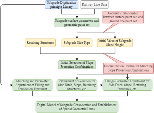
To streamline mass batch projects, a rapid and efficient design process is proposed, with the implementation process of this method shown in Figure 3:
(Establish a digital subgrade principle library, which includes facility libraries for the subgrade surface, filling, side ditches, slopes, and retaining structures, as well as a combination library for slope protection matching;
Select the subgrade surface type and calculate the shoulder height using alignment data, then create the geometric point set for the subgrade surface;
Analyze the spatial relationship between the point set of the subgrade surface and the ground line point set to determine the subgrade type on the left and right sides (embankment or cutting);
Preliminarily select the slope protection combination for both sides of the subgrade based on the subgrade type, retaining structure type, and subgrade height.
Select facilities from their respective libraries within the slope protection combination, or directly adjust the design parameters of the facilities.
Select the filling and foundation treatment from the library, and adjust the design parameters as needed;
Finalize the digital model of the subgrade cross-section and construct the geometric model of the subgrade based on the digital model
3.3 Construction of digital base
The proposed design process ensures the construction of a digital base, where various data formats are unified, defined clearly, and classified reasonably through standardized and normalized data processing, guaranteeing data accuracy, consistency and management.
Specifically, subgrade parts are transformed into spatial geometric models and stored in point sets to achieve data structuring, facilitating rapid computation, querying, and establishing data links. This approach fulfills the integrity and correlation requirements. At the same time, the system’s scalability enables the digital base to accept new data efficiently, and a well-structured architecture is also conducive to data maintenance, ensuring its availability and reliability.
Furthermore, the amalgamation and integration of multi-source data are evident throughout the various phases of design data, furnishing a holistic analytical framework for geological and design parameters. Cross-disciplinary data integration underpins collaborative work. The digital base lays the data foundation for collaborative work platforms, supports real-time communication and collaborative work among all parties, and drives intelligent applications.
4. Program development and application
4.1 Digital design system
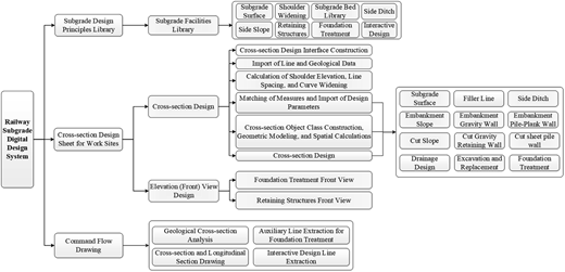
Based on the digital modeling and design methods proposed in Sections 2 and 3, a digital design system for railway subgrade cross-sections was developed using object-oriented programming technology in C++, with the key code listed in Appendix B. This system includes a digital subgrade design principle library stored in Excel format and algorithms and modules based on parametric subgrade spatial geometric models. It enables batch, rapid, and digital design of railway subgrade cross-sections. The system is independent of third-party software platforms during the design and computation stages. For displaying design results, the system only uses drawing software to generate graphical elements such as points, lines, and text, allowing digital design results to be presented without relying on AutoCAD or any other specific drawing platform.
The system’s overall architecture and interface are shown in Figure 4, wherein the key inputs comprise railway alignment data and geological cross-sections obtained through surveying. The alignment data mainly consists of three basic types: alignment chain information, horizontal intersection point information, and vertical profile gradient information, which are used to determine the mileage, direction, and elevation of the railway alignment. The format of the geological cross-sections is shown in Figure 1. The design output of the program is the subgrade cross-section, with a prototypical result illustrated in Figure 5.
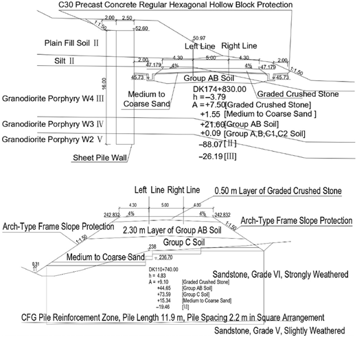
Progress of digitally-designed subgrade cross-section. Source: Authors’ own work
Progress of digitally-designed subgrade cross-section. Source: Authors’ own work
The program’s input data comprises alignment data and geological sections. Specifically, the alignment data encompass three fundamental datasets: alignment chain, planar intersection point and longitudinal profile gradient. They are utilized to determine the alignment mileage, the planar alignment direction and elevation information of the railway. The format of the geological mapping is presented in Figure 1. The outcome of the program is the subgrade section, with the typical section illustrated below.
4.2 Current and future applications
Currently, the established system has been widely applied in several railway projects, including the Baotou-Yinchuan HSR, Shenyang-Baihe HSR, Weifang-Yantai HSR, and Jining-Datong-Yuanping HSR. The aforementioned practice indicates more than 60% of efficiency increase in railway design.
4.3 Discussion
The above digital design methods hold the potential to significantly bolster collaborative construction efforts and operational considerations grounded in design principles. From a construction perspective, different construction plans can be simulated and analyzed based on proposed digital models to clarify the impact of factors such as construction sequence, construction methods, and resource input on project progress, quality, and safety, thereby improving collaborative efficiency during the construction process. For example, various combinations of excavation sequences, construction time and slope protection plans can be pre-simulated in the digital design process, yielding the optimal construction plan. In addition, the design process includes systematic considerations such as subgrade types and protection combinations, enabling operation and maintenance personnel to deeply understand design intentions and structural characteristics and determine key monitoring locations or performance indicators. For example, for roadbed sections that use a specific slope protection combination (such as slope + gravity retaining wall), the monitoring focus is the displacement of the retaining wall and the stability of the connection between the slope and the retaining wall.
The proposed digital design method and system are highly scalable, facilitating the seamless integration of retaining structures and drainage facilities such as footwalls and ditches. Moreover, this method transcends the realm of railway subgrades, making it versatile enough to revolutionize transportation engineering design for municipal roads, highways, slopes, and various other areas.
5. Conclusion
This study proposed a digital analysis and geometric modeling method for railway subgrade sections through advanced digital analysis and modeling techniques. Subsequently, a parametric design principle library for various facilities is established, encompassing six critical earthwork components: subgrade surfaces, filling, slopes, retaining structures, foundation treatments, and slope protection combinations. Additionally, a practical digital design system was developed using C++, founded on the aforementioned models and methodologies.
Validation through practical implementation demonstrates significant performance improvements, with the open-source framework achieving over 60% efficiency gains in design workflows during its deployment on three major high-speed rail projects: the Baotou-Yinchuan, Shenyang-Baihe and Weifang-Yantai HSR lines. Overall, this innovative approach significantly enhances efficiency, intelligence, and versatility by decoupling subgrade design from traditional drawing platforms, laying a digital foundation for intelligent design and maintenance of the next-generation high-speed railway.
This research was supported by the major project of China State Railway Group Co., Ltd. (No. Q2023G020) and the internal project of China Railway Design Cooperation (No. 2023A0248002).
Conflict of interest: The authors declare that they have no known competing financial interests or personal relationships that could have appeared to influence the work reported in this paper.
Corrigendum: It has come to the attention of the publisher that the article, Qingbo Bai, Xu Li, Zhenze Ma, Xiaokang Li, Long Liu; A novel digital design method for railway subgrade sections. Railway Sciences 27 June 2025; 4 (3): 375-387. https://doi.org/10.1108/RS-11-2024-0046, has included Figure 6 in error. Figure 6 has been removed following the request of the authors in order to comply with local regulations and institutional requirements. This figure was for illustrative purposes and does not affect the interpretations of the findings of the article.
References
The supplementary material for this article can be found online.

