

With rapid infrastructure construction and urban redevelopment, there has been an increasing demand for utilisation of underground spaces, which gives rise to a large number of excavation projects. In the past decade, a series of new trends have emerged on excavation engineering in Shanghai, China. As available ground resources in congested urban areas are scarce, excavations become much larger and deeper than before. More excavations have to be carried out in close proximity to existing buildings, tunnels, utilities and other structures. Any severe damages to the nearby utilities probably lead to economic losses and complicated conflicts among owners, tenants, utility customers and the public. As a consequence, it is of great concern not only to ensure the safety of the excavation itself but also to mitigate adverse excavation-induced influences on the adjacent environment. This paper presents recent developments in practical design and construction techniques of controlling excavation-induced deformations in Shanghai. Commonly used techniques including the top-down construction method, ground improvement, the zoned excavation method and the underpinning technique are described and discussed. Relevant instrumented case histories on excavations in different types of urban environment are reported as well.
Introduction
Shanghai is one of the important global financial centres with a population of more than 24 million as of 2016. In the past three decades, unprecedented economic development and urbanisation have lead to an increasing requirement of large underground spaces, which can serve as basements of high-rise buildings, metro tunnels and stations, underground power stations and infrastructures of various kinds. As readily available ground resources are extremely scarce particularly in urban areas, property developers tend to specify deep basements to maximise land use. All the trends call for larger and deeper excavations than before. Nowadays, large-scale deep excavations with an area of more than 100 000 m2 are not rare. Figure 1(a) shows a typical large project of the Shanghai Hongqiao international airport transport hub, which covers a footprint of 350 000 m2. It is the biggest transport centre in China, consisting of interchange stations for five different metro lines, two traffic squares, a high-speed railway station and a station for the maglev train connecting the Hongqiao and Pudong international airports (Wang et al., 2015). For Shanghai International Financial Center in Figure 1(b), the area of the excavation is 42 000 m2 and its depth ranges from 26·6 to 28·1 m. Both bottom-up and top-down construction methods have been used to construct the project.
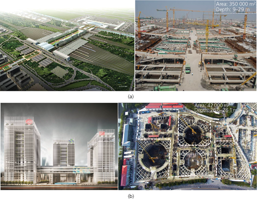
Typical deep and large excavation projects in Shanghai: (a) Hongqiao international airport transportation hub; (b) Shanghai International Financial Center
Typical deep and large excavation projects in Shanghai: (a) Hongqiao international airport transportation hub; (b) Shanghai International Financial Center
Deep excavation has the potential to cause unfavourable effects on nearby ground as well as structures and facilities around it. With the increasing number of excavations constructed in congested urban areas, it is necessary not only to ensure the safety of the excavation but also to minimise ground and wall displacements and hence to guarantee the serviceability of adjacent properties. Typically, existing structures located in close proximity to an excavation involve but are not limited to buildings founded on shallow and pile foundations, pipelines, metro tunnels and stations (see Figure 2), which are referred to as environment hereafter. Although the design and construction of excavations are stringently regulated by national and local codes, unexpected damages to adjacent environment occur from time to time. It is always a challenge for geotechnical engineers to take appropriate measures to mitigate excavation-induced deformation so as to minimise its effect on nearby sensitive buildings and utilities, particularly in soft clays. As a consequence, more issues have to be considered thoroughly throughout the design and construction of excavations in a complex urban environment.
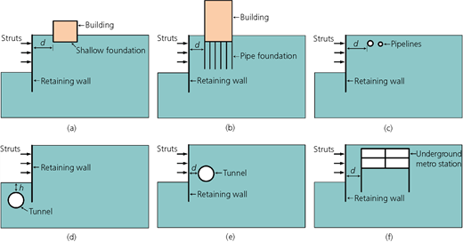
Structures located adjacent to excavations in urban areas: (a) building resting on shallow foundation; (b) building resting on pile foundation; (c) pipelines; (d) underlying tunnel; (e) adjoining tunnel; (f) underground metro station
Structures located adjacent to excavations in urban areas: (a) building resting on shallow foundation; (b) building resting on pile foundation; (c) pipelines; (d) underlying tunnel; (e) adjoining tunnel; (f) underground metro station
In this paper, recent developments in practical design and construction techniques of controlling excavation-induced deformations in Shanghai are presented. Commonly used techniques including the top-down construction method, ground improvement, the zoned excavation method and underpinning are described and discussed, giving details of procedures involved and both advantages and drawbacks faced in each method. Relevant instrumented case histories along with experiences on excavations in different types of urban environment are reported as well.
Typical geological conditions in Shanghai
Shanghai is located at the estuary of the Yangtze River delta. During the late Tertiary and Quaternary periods (about 3 million years ago), the delta was subjected to alternating marine transgressions and regressions due to climate changes. The geology is composed of very thick (around 150–400 m) complex deposits consisting of thick clay layers sandwiched by sand layers (confining aquifers). The top 40–50 m soils are most frequently encountered in geotechnical engineering work. Gao et al. (1986) divided the uppermost 50 m soils in Shanghai into eight layers as described in Table 1. The top two layers are fill and yellowish silty clay. The second layer is overconsolidated and commonly referred to as stiff surface crust. Following are soft clay layers of thickness ranging from about 10 to 20 m. The soft clay has relatively larger natural water content, void ratio and compressibility but lower shear strength. Underneath the soft clay are layer 5, silty clay, and layer 6, dark-green stiff clay. Unlike the normally consolidated layer 5, layer 6 is overconsolidated and has a thickness of about 3 m only. Subsequent to clay layers is a very fine-to-fine sand layer which is the first aquifer with a hydraulic head of about 3–8 m below ground surface.
Description of typical Shanghai soil strata (modified from Gao et al. (1986))
| Sequence | Soil description | Thickness: m | Geological origin | Notes |
|---|---|---|---|---|
| ① | Fill | <3 | River estuary alluvial deposits | |
| ② | Silty clay | 2–3 | Overconsolidated (stiff surface crust) | |
| ③ | Soft silty clay | 5–10 | Shallow sea deposits | Normally consolidated |
| ④ | Soft clay | 3–10 | ||
| ⑤ | Silty clay | 5–15 | Littoral shallow sea marsh deposits; littoral-fluvial deposits | |
| ⑥ | Stiff clay | ∼3 | Lacustrine deposits | Overconsolidated |
| ⑦ | Very fine-to-fine sand | 5–15 | Fluvial deposits | Aquifer I |
| ⑧ | Silty clay | 20–30 | Shallow sea deposits |
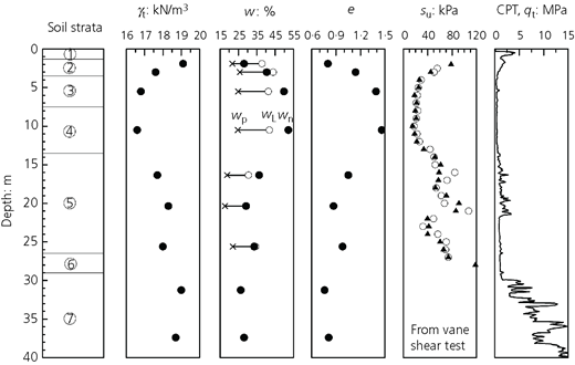
A typical soil profile and soil properties in Shanghai are shown in Figure 3. The unit weight (γt) of soils decreases from 19 kN/m3 near the ground surface to 16·5 kN/m3 at 10 m below ground in the soft/silty clay layer and then increases to 19 kN/m3 below 30 m. For the soft (silty) clay layers, the measured values of natural water content (wn) are greater than the liquid limit of each soil, suggesting the soft and compressible nature of the soils. The undrained shear strength obtained from in situ vane shear tests is less than 40 kPa. The variations in the measured void ratio (e0) are consistent with the profiles of γt and wn. The tip resistance qt obtained from a cone penetration test increases gradually with depth in clay layers, whereas it increases suddenly to an average value of 10 MPa in the sand layer. The measured permeability of clay layers is on the order of 10−8 m/s, while the value for the fine sand (aquifer I) can be as high as 10−5 m/s (Wang and Xu, 2012). The main ground water table is generally located at 0·5–1·0 m below the ground surface.
Deformation criteria
The design and construction of deep excavations in the urban environment is often governed by the tolerance of the adjacent environment to excavation-induced deformations. Precise prediction of the deformations due to a deep excavation using advanced numerical analysis is not simple because of the uncertainties in geological conditions, three-dimensional nature of the problem, incorporation of human factors and so on. Assessment on local reliable and well-documented case histories is an alternative approach to provide limiting deformation criteria against unacceptable damages and to give some guidelines for geotechnical engineers to make reasonable predictions.
In Shanghai, deep excavations can be categorised into three protection levels, depending on types of adjacent properties as well as their distance from the excavation (Table 2). For each level, the relationship between the maximum lateral wall displacements and excavation depth has been thoroughly investigated by using statistical methods on the basis of a large number of heavily instrumented case histories. The mean value of the measured maximum lateral wall displacement is set to be the permissible wall displacement. The limit values of maximum wall displacement are found to be 0·18% H, 0·3% H and 0·7% H (H is excavation depth) for class I, II and III excavations, respectively. The maximum ground surface settlements are approximately 0·8 times the permissible maximum lateral wall displacement for all cases. According to practices in Shanghai, existing structures and properties have rarely been damaged as long as excavation-induced deformation is stringently controlled based on the criteria given in Table 3.
Classification of excavations according to adjacent environment (SUCTC, 2010)
| Neighbouring conditions (type of structures and other properties adjacent to excavations) | Distance away from the excavation, s | Protection level |
|---|---|---|
| Historic buildings, industrial plants with precise equipment and machinery, important buildings on shallow foundations or short pile foundations, metro tunnels, flood walls and other important infrastructures such as water, gas and sewer networks | s ≤ H | I |
| H < s ≤ 2H | II | |
| 2H < s ≤ 4H | III | |
| Normal buildings on shallow foundations or short pile foundations, infrastructures such as water, gas and sewer networks | s ≤ H | II |
| H < s ≤ 2H | III |
H, excavation depth
Deformation criteria on excavations in Shanghai (SUCTC, 2010)
| Protection level | Permissible maximum wall displacement | Permissible maximum ground settlement |
|---|---|---|
| I | 0·18% H | 0·14% H |
| II | 0·3% H | 0·25% H |
| III | 0·7% H | 0·55% H |
Environmental protection techniques
It is well acknowledged that removal of soil with the excavation process would inevitably lead to stress changes initiating noticeable ground deformations, the influence zone of which can extend to several times the excavation depth behind the wall. As illustrated in Figure 4, protection of the nearby environment can be achieved by (a) controlling deformations associated with excavations within desirable limits, (b) installing a barrier between the excavation and nearby structures to block the spread of induced deformations and (c) increasing the ability of affected structures to resist the deformations. Four commonly used protection measures – the top-down construction method, ground improvement, the zoned excavation method and underpinning – will be discussed, giving details of procedures involved and both advantages and drawbacks faced in each method.
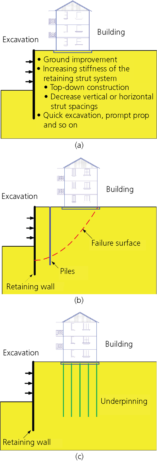
Mitigation of adverse influences on the nearby environment by (a) controlling excavation deformations, (b) installing a barrier to block spread of deformations and (c) increasing the structure’s ability to resist excavation-induced deformations
Mitigation of adverse influences on the nearby environment by (a) controlling excavation deformations, (b) installing a barrier to block spread of deformations and (c) increasing the structure’s ability to resist excavation-induced deformations
Top-down method
In contrast to the bottom-up method, in the top-down method, floor slabs and beams are cast first and then excavation and construction of the basement proceed downwards at the same time. It is effective for minimising lateral wall displacements, as retaining walls are restricted by floor slabs which are stiffer than temporary reinforced concrete or steel struts. Wang et al. (2010) collected wall displacements from a total of 232 deep excavations in different types of neighbouring environment. Among these cases, 200 excavations were constructed by using the bottom-up method, while the other 32 excavations by the top-down method. As demonstrated in Figure 5, the maximum average wall displacement δ hm for the top-down system is about 0·27% H, less than the value of 0·4% H for those using the bottom-up method. The direct comparison suggests that the top-down method is a suitable option to minimise wall displacements and reduce adverse effects on adjacent properties in Shanghai soft clay.
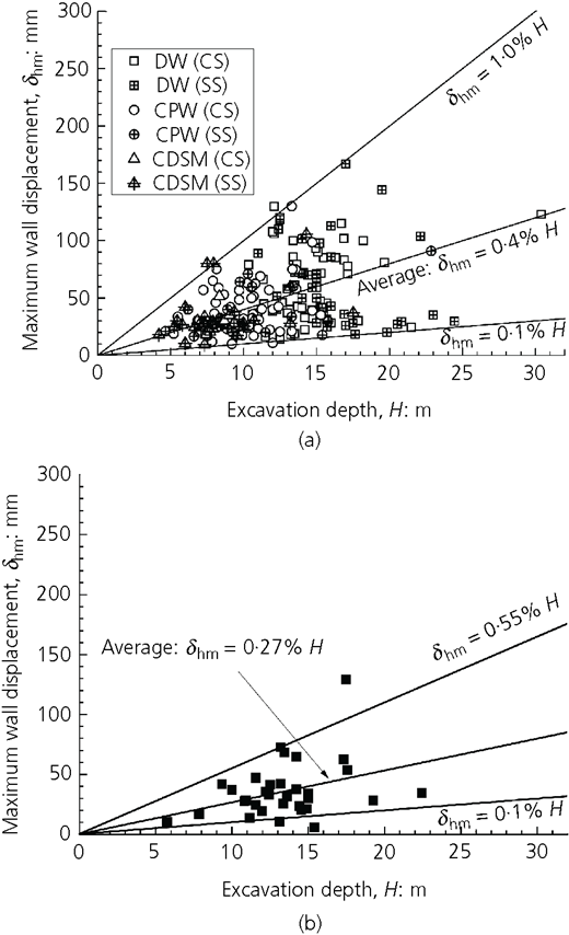
Comparison of maximum lateral wall displacements for excavations constructed using the (a) bottom-up method (DW, CPW and CDSM) and (b) top-down method (Wang et al., 2010). CDSM, compound deep soil mixing; CPW, contiguous pile wall; CS, concrete strut; DW, diaphragm wall; SS, steel strut
Comparison of maximum lateral wall displacements for excavations constructed using the (a) bottom-up method (DW, CPW and CDSM) and (b) top-down method (Wang et al., 2010). CDSM, compound deep soil mixing; CPW, contiguous pile wall; CS, concrete strut; DW, diaphragm wall; SS, steel strut
Figure 6 shows the excavation of the Shanghai 50 kV World Expo Underground Transmission and Substation, where only underground structures were continuously constructed together with downward excavation. Several openings were left in roof slabs, allowing for transportation of spoil, materials and machinery as shown in the figure. An extension of the conventional top-down method is the concurrent upward and downward method, also called the up–down method, in which excavation and construction of superstructures are carried out simultaneously upon the completion of roof slabs. Figure 7 shows the excavation of the Jing’an transportation hub, which was intended to alleviate the traffic congestion problem in the densely populated area. The contractor expected podiums to be open for use before all the basements are completed. In this case, it was advantageous to use the concurrent upward and downward method to expedite the construction. In the end, not only the total construction programme but also loan interests were saved. The trend that more projects are constructed under a fast-track schedule may also be an important driver to the growing popularity of the top-down construction method.
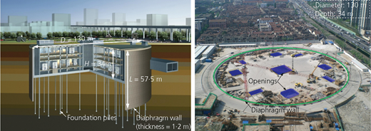
Excavation of Shanghai 50 kV World Expo Underground Transmission and Substation
Excavation of Shanghai 50 kV World Expo Underground Transmission and Substation
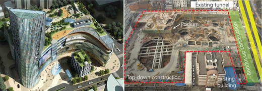
Excavation of Jing’an transportation hub constructed using the concurrent upward and downward method (excavation area = 16 000 m2, excavation depth = 14·5–15·2 m)
Excavation of Jing’an transportation hub constructed using the concurrent upward and downward method (excavation area = 16 000 m2, excavation depth = 14·5–15·2 m)
Ground improvement
The top 40 m soil deposits in Shanghai are relatively soft (refer to Table 1 and Figure 3). The deformations of retaining structures could not be fully controlled by only increasing wall stiffness when excavations are carried out in such soft ground. It is therefore necessary to increase ground stiffness and hence to restrain lateral wall deformations by improving soils inside the excavation using deep soil mixing or jet grouting. For the deep mixing method, the soil is loosened and mixed with cement slurry by two or three adjoining slightly overlapping augers and mixing paddles. Equipment with three augers can improve soil at greater depths than that with two augers. Instead of a mechanical mix, in jet grouting the soil is rearranged and mixed with the cement suspension with the aid of high pressures. Typical design parameters of each method applied in Shanghai are summarised in Table 4, including water–cement ratio, mass of cement slurry and 28 d unconfined compressive strength.
Design parameters of ground improvement techniques
| Ground improvement techniques | Mass of cement slurry: % | Water–cement (w/c) ratio | 28 d unconfined compressive strength: MPa |
|---|---|---|---|
| Deep soil mixing (dual-auger) | 13 | 0·45–0·6 | ≥0·6 |
| Deep soil mixing (triple-auger) | 20 | 1·5–2·0 | ≥0·8 |
| Jet grouting | 25 | 0·8–1·5 | ≥1·0 |
A number of variations in soil improvement arrangement are applied in practical excavation work, largely depending on geological conditions of the construction site and neighbourhood environment conditions. The arrangements include block type, wall type, strip type and edge type (Figure 8). It is clear that block type and strip type are the most efficient in resisting lateral wall deformation because of the higher volume of treated soil, but on the other hand, they are much more expensive. In view of the economic aspect, the wall type and edge type (soil along the inner periphery of retaining wall is improved) are more frequently used in practice in Shanghai.

Arrangement of soil improvement inside excavations: (a) block type; (b) wall type; (c) strip type; (d) edge type
Arrangement of soil improvement inside excavations: (a) block type; (b) wall type; (c) strip type; (d) edge type
Zoned excavation
The zoned excavation method is often applied in large-scale excavations where the construction site is separated into smaller zones and the excavation process is carried out zone by zone. Reducing the area can speed up the excavation process and the construction of struts for each zone to form a complete retaining system sooner. This is important for projects in soft clay where secondary compression may take a noticeable proportion of wall and ground deformations if the construction lasts for a long period. The excavation procedure in each zone is similar to conventional approaches.
As shown in Figure 9(a), a large-scale excavation is divided into two comparable zones, A and B. Each zone takes a different construction method according to the nearby environment conditions. Area A, which is far away from the existing buildings, is constructed firstly using the bottom-up method while keeping area B intact. Since the buildings are beyond the main influence zones of area A because of the existence of area B in between, the excavation-induced influences on the buildings are supposed to be limited during this stage. After the completion of underground structures in area A, it proceeds to the construction of area B by using the top-down method. As a result of the large lateral stiffness that the top-down method can provide, the effect of excavation on buildings tends to be less significant.
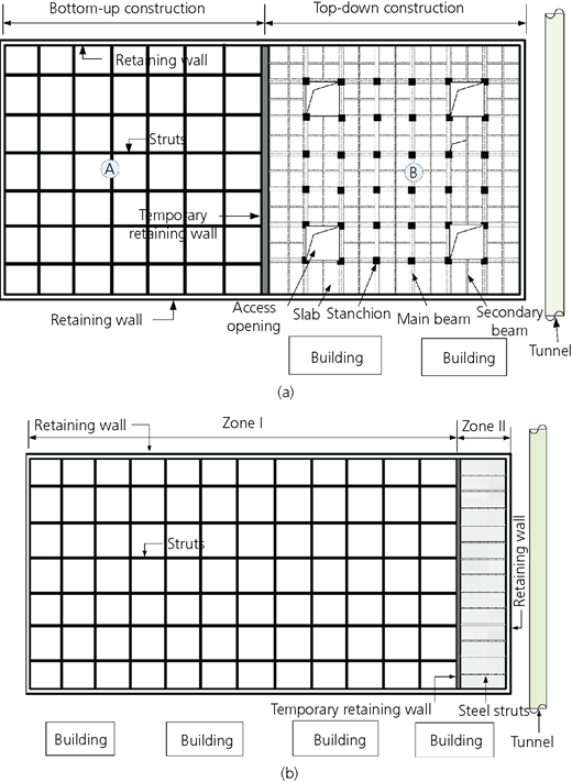
Schematic diagram showing zoned excavation: (a) combination of bottom-up and top-down construction; (b) zoned bottom-up construction
Schematic diagram showing zoned excavation: (a) combination of bottom-up and top-down construction; (b) zoned bottom-up construction
Figure 9(b) shows another common practice, that of splitting an excavation into a large area (zone I) together with a narrow rectangular one (zone II) in an attempt to ensure the safety of adjacent existing tunnels and metro stations. Based on practical experiences, the small rectangular area is generally set to be about 20 m wide. Prior to construction, the soil in the small area is improved by the deep mixing method in a block type. The rectangular area thus functions like a rigid wall that can reduce the magnitude of soil and tunnel movements towards the excavation. For some cases, the rectangular area would be further divided into a number of sections, each of which is about 50 m long.
The narrow excavation is generally supported by steel pipe struts with a diameter of 609 mm, which are mounted on steel wale beams or directly on diaphragm walls. In order to conform to the stringent regulation on tunnel movement of less than 20 mm, a novel load-compensation servo system as shown in Figure 10 has been developed. The system is able to monitor the strut load constantly in the course of construction and to adjust the axial loading automatically once the observed value deviates largely from the permissible limit. The successful application of the strut system in a variety of projects has proved it to be a reliable and efficient technique to reduce excavation-induced influences on nearby metro tunnels and stations.
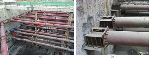
(a) Load compensation servo for steel struts; (b) close-up of the connection between retaining wall and the servo. RC, reinforced concrete
(a) Load compensation servo for steel struts; (b) close-up of the connection between retaining wall and the servo. RC, reinforced concrete
Underpinning
When a structure is located within the primary influence zones (Hsieh and Ou, 1998), excessive settlements and large angular distortions may be generated, causing unintentional damage to the existing structure. This damage does not depend only on the induced ground deformations but also on the structural sensitivity of the affected building. Masonry load-bearing walls or frames with masonry infill walls resting on shallow foundations are most vulnerable to differential settlement. Under certain circumstances, it is required to underpin a structure as a safeguard against possible settlements before the start of excavation. ‘Underpinning’ is a broad term for describing the process of installing new supports under an existing foundation. There is a variety of underpinning methods, and the selection of an appropriate underpinning technique is dependent on geotechnical conditions, access to foundations, type of existing building foundation, type of building structure and magnitude of the building loads.
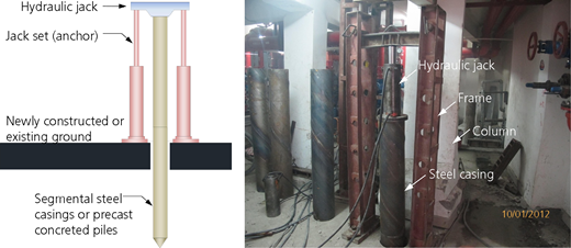
Shanghai City has a great many historic buildings which were constructed in the late nineteenth or early twentieth century. Most of the buildings are typically composed of load-bearing brick walls and columns supported on shallow foundations. These buildings are delicate and vulnerable to ground movements of small magnitude. The jack-down piling method has been used in Shanghai to reinforce fragile buildings in urban areas since it is almost silent and vibration-free. After the provision of a suitable reaction medium – for example, existing or newly constructed reinforced-concrete ground – segmental steel casings or precast concrete piles are jacked in sections to a designed depth, as can be seen from Figure 11. The piles are concreted and bonded to existing columns. Because of the unique size and adaptability of jack rigs, the jack-down piling method can be used in the most difficult areas with small operating clearance.
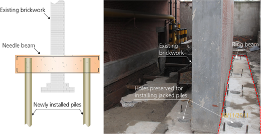
To protect the brick walls of the delicate buildings, a pair of piles is installed on either side of the affected wall. A pocket of brickwork is then removed, and a steel cage is installed to span over the two piles at intervals. To improve the integrity of the new foundation, the needle beams are often connected by a reinforced-concrete beam as shown in Figure 12. Compared with traditional underpinning methods which entail a large amount of excavations and labour, the aforementioned underpinning techniques are quicker and result in less disturbance to the buildings to be underpinned.
Case histories
Xingye Building (case 1)
Figure 13 shows the plan view of excavation for Xingye Building, which is located in the old downtown of Shanghai. The building has 19 floors above the ground and a three-level basement. The excavation depths of the west and east sides of the basement were 14·4 and 12·4 m, respectively. The construction site, covering a footprint of 7800 m2, was adjacent to 15 existing buildings, among which buildings A–H were historic buildings. Building A is a reinforced-concrete frame structure constructed in 1949. It is rested on a piled box foundation, which utilises wooden piles driven into a stiff clay layer. The distance from the periphery of the excavation to the historic building was about 8·0 m. Moreover, a large number of old pipelines were embedded underneath Hankou Road and Sichuan Road. Anxiety regarding safety may arise if excavation activities lead to cosmetic or further structural damages to these old buildings. The excavation is hence classified as class I with respect to protection level as indicated in Table 2. The top-down construction method was adopted in an attempt to protect the old buildings and pipelines. A 1 m thick diaphragm wall was installed to a depth of 31·2 m at the west and south sides that were close to the existing historic buildings, while a 0·8 m thick diaphragm wall was used for the north and east sides. To reduce the effects of wall installation on the delicate buildings, each wall panel was 4·2 m long rather than the common practice of 6 m in Shanghai. Concrete-filled steel tubes with a diameter of 609 mm were taken to support the vertical loading of underground structures in the course of excavation, and the steel tubes were finally encased with concrete to form the permanent columns. In addition to adopting a top-down method, peripheral 6 m wide soil inside the excavation was improved from the ground surface to 5 m below the formation level to enhance the resistance to lateral ground and wall deformations.
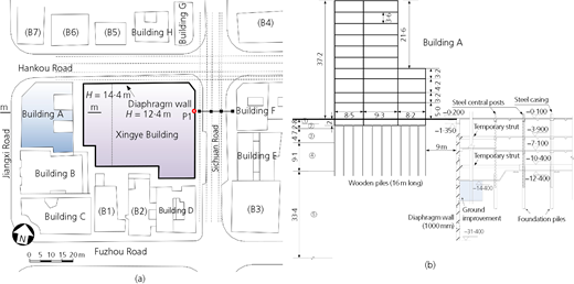
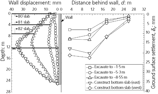
Figure 14 shows the development of lateral wall displacements at P1 as well as corresponding ground surface settlements behind the wall. Prior to the construction of roof slabs, cantilever-type wall displacement was observed when soil was removed. Afterwards, since the top of the wall was resisted by the roof slab, a deep-seated profile developed as the excavation proceeded downwards. Upon completion of bottom slabs, the measured maximum lateral wall movement was 37·9 mm, which is equal to about 0·3% of the excavation depth (H). As expected, the ground surface settlement δ v decreased with an increase in the distance from the diaphragm wall. δ v reached its maximum value of 22·4 mm at about 10 m behind the wall and then decreased gradually. The ground surface settlement profile turns out to be a concave type (Ou, 2006), and the influence zone extends to at least 2H behind the wall. The ratios of δ v-max to δ h-max range from 0·6 to 0·7, slightly less than the results measured by Ng et al. (2012) in a narrow rectangular excavation.
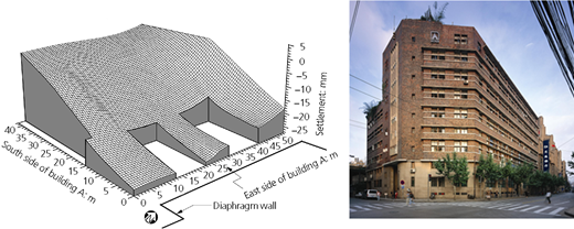
According to the evaluation report of building A, some cracks already existed in the infilled brick walls prior to excavation. Figure 15 shows the settlement profile of building A at the final excavation stage. Although the maximum settlement of the building was up to 27·2 mm, the measured maximum angular distortion was about 1/780, which was less than the empirical limit value of angular distortion of 1/500 for a reinforced frame structure proposed by Polshin and Tokar (1957). As a result, the structures of the building did not experience extra damage in the course of excavation.
Jing’an Transportation Hub (case 2)
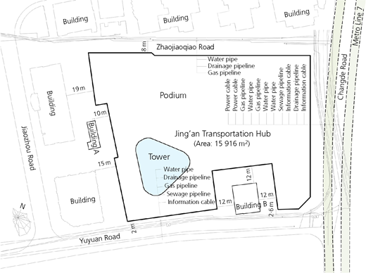
The Jing’an Transportation Hub was located in the downtown area of Jing’an District. The project comprised a 20-storey tower and eight-storey podiums equipped with a three-level basement (refer to Figure 7 for the architectural drawings). The construction site occupied an area of about 15 916 m2. As shown in Figure 16, there existed roads, metro tunnels, buildings and various types of pipelines around the site. The shield tunnels of Metro Line 7 (in service) run parallel to the east side of the excavation and were embedded about 10 m underneath the Changde Road. The minimum distance between the tunnels and the excavation was only about 8·6 m. On the south side stood an old building, building B, which was about 12 m away from the excavation. The building had eight storeys and was rested on piled raft foundations with a pile length of 18 m. The buildings on the east side were also close to the site. The excavation depth at the tower area was 15·0 m and ranged from 14·5 to 15·2 m for the podium area.
Considering the excavation area, the excavation depth and the protection requirements of the adjacent facilities, the zoned excavation technique was adopted in this project. The excavation was divided into a relatively large pit (zone II) and a small one (zone I), as shown in Figure 17. Zone I was 16·3 m wide and adjacent to the metro tunnels. The two excavations were separated by a temporary diaphragm wall in between. Zone I was constructed first by the bottom-up method. Upon the completion of underground structures in the small area, zone II was constructed by using the top-down method.
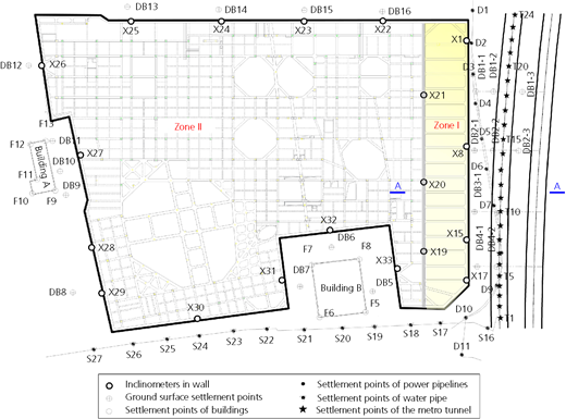
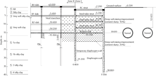
The small narrow excavation (zone I) was retained by a 1000 mm thick diaphragm wall along the side adjacent to tunnels. The embedded length – that is, the wall length below the final formation level – was 22·9 m, while a 800 mm thick diaphragm wall was installed to be the temporary retaining wall between the two zones. The excavation was supported by four levels of struts. The first-level prop used 800 mm × 800 mm reinforced-concrete struts, while the other three utilised steel tube struts with a diameter of 609 mm and a thickness of 16 mm. All the struts were installed at a 6 m spacing in plan. Instead of using reinforced-concrete or steel struts, structural slabs were used to resist lateral wall displacements in zone II. The roof slab (B0) was designed as a platform for soil excavators, trucks and other construction machines to move on. Big access openings (see Figure 17) were left in the roof slabs to facilitate the transportation of soil spoil and delivery of building materials. A big opening was also left at the tower area. The excavation at this part was temporarily supported by reinforced-concrete struts. Upon completion of bottom slabs, the tower building was constructed upwards. Details of retaining structures can be referred to in Figure 18.
The excavation was heavily instrumented (refer to Figure 17), and the responses of retaining structures together with nearby tunnels, buildings and pipelines were continuously monitored throughout construction. Figure 19 compares lateral displacement profiles of diaphragm walls in zone I and zone II. It can be seen that the lateral displacement of the walls gradually developed into a deep-seated profile as the excavation proceeded downwards. From the second level of strut (−6·1 m) to the formation level, all excavation activities were carried out in soft (silty) clay layers. As expected, lateral wall displacement increased significantly accordingly. The maximum lateral wall deflections δ m of X1 and X8 were 16·7 and 20 mm, being equal to 0·11% H and 0·13% H, respectively. It took about 10 d to cast bottom slabs. During this period, a noticeable lateral displacement increment was observed. It can also be found that the maximum lateral displacement generally occurred underneath the formation level in the bottom-up-constructed area.
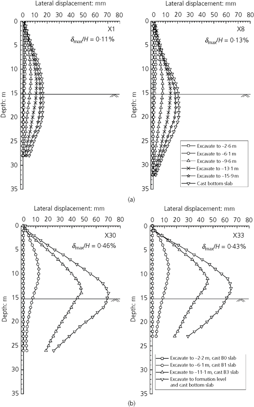
Figure 19(b) shows typical lateral wall displacement at X30 and X33 in zone II. The wall displacement profile agreed broadly with those in zone I, but the magnitude was much larger. The maximum wall deflections δ m of X30 and X33 were 70·2 and 60·5 mm, being equal to 0·46% H and 0·40% H, respectively. The larger wall displacements may be attributed to the following reasons: (a) the area of zone I was much smaller than that of zone II so that the excavation of zone I was much faster; (b) the average vertical strut spacing in zone I was smaller than that in zone II; (c) a thicker diaphragm wall was used for the retaining structures adjacent to the tunnels; and (d) the entire area of zone I was fully improved, while in zone II only the peripheral passive zones were improved. The maximum lateral displacement occurred above the formation level, being similar to the wall responses observed in Xingye Building, which used the top-down method as well (see Figure 14).
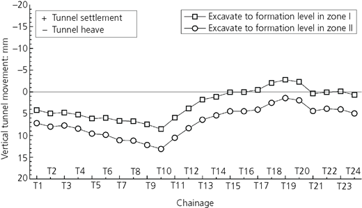
Figure 20 shows the vertical tunnel movements along the longitudinal tunnel axis. When zone I was excavated to the formation level, most of the tunnel linings moved downwards except for locations from T17 to T21. The maximum tunnel settlement and heave were 8·5 and 2·8 mm, respectively. During the subsequent excavation of zone II, tunnel linings moved downwards almost uniformly. Another 4·5 mm settlement was recorded during the period. When excavation in zone II was finished, the maximum settlement of the tunnel was found to be 13·1 mm, which was within the acceptable limit of 20 mm (Hu et al., 2003). The maximum angular distortion was 0·059%, occurring near T10. No obvious structural damage was observed to tunnel linings, and the normal service of the metro line was rarely affected by construction activities of the excavation.
DingDing Bund Building (case 3)
A four-storey basement for the DingDing Bund Building was constructed in the bund area in downtown Shanghai. Figure 21 shows the plan view of the site. The construction of the basement involved an excavation of 20 000 m2 area and 19·8 m depth supported by diaphragm walls. As the site is located in the downtown area, the environment in the proximity of the excavation is very complex. There were three buildings – the main building, south building and north building – which were built in 1906 and have been preserved as historic buildings on the north-east of the excavation. All the three buildings were reinforced masonry buildings, which used brickwork as load-bearing walls and steel pipes or reinforced concrete to construct structural columns. Most of the loading-bearing walls and interior columns were rested on stepped spreading footings made of brick. The closest distance from the excavation to the buildings was only about 3·0 m.
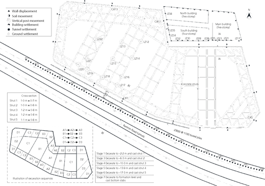
On the south of the excavation lay the Renmin Road tunnels, which ran across Huangpu River connecting the Pudong and Puxi areas. The two tunnels were 6·7 m apart and embedded about 14–22 m below the ground surface. The tunnel diameter was 11·36 m. As shown in the figure, the minimum distance between the excavation and the tunnels was 9 m. Moreover, there were bund tunnels and a lot of pipelines around the excavation. The details of the bund tunnels and pipelines are not presented in this paper.
As the environments around the excavation were complicated, 1000 mm thick diaphragm walls that were supported by five levels of concrete struts were adopted for most areas. The dimensions of each level of struts are given in Figure 21. The first level of struts used C30 concrete whose 28 d compressive strength was 14·3 MPa. For the remaining struts, C40 concrete with compressive strength of 19·1 MPa was adopted. The embedded depth of the diaphragm wall varied from 18·0 to 34·0 m along the perimeter of the excavation depending on both geological conditions and adjacent environments to be protected. Two rows of mixed-in-place piles were constructed along either side of the diaphragm wall to reduce the influence of wall installation on adjacent environments. Moreover, soil at the excavated side from underneath the second-level strut to 6 m below formation level (shadow area as shown in Figure 22) was improved by the triple-auger deep mixing method.
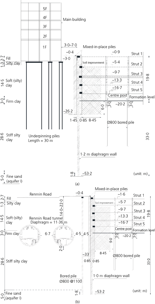
Relationship between excavation and adjacent (a) historic buildings and (b) tunnels
Relationship between excavation and adjacent (a) historic buildings and (b) tunnels
In order to protect the historic buildings, the thickness of the diaphragm walls near the buildings was increased to 1200 mm. During the design stage, the authors proposed to the contractor to underpin the three historic buildings. However, due to some unknown reasons, this work did not start until the completion of diaphragm wall installation. The procedures of underpinning outside brick walls are illustrated in Figure 23. The ground was first excavated to a certain depth to expose the spread footings, where a pocket of brick was removed at intervals. Segmental steel pipes were then jacked down to a depth of 30 m on either side of the wall. Steel cages were installed to span over the brick foundation to form a needle beam. Finally, concrete was poured to allow for a connection of jack-down piles, needle beams and the ring beam. The interior columns were also underpinned by jack-down piles which were connected by a newly constructed reinforced-concrete slab.
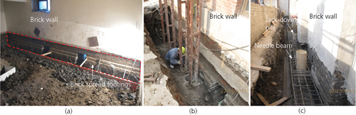
Photographs showing the sequence of underpinning work: (a) excavation; (b) installation of jack-down piles; (c) installation of steel cages
Photographs showing the sequence of underpinning work: (a) excavation; (b) installation of jack-down piles; (c) installation of steel cages
To reduce the influence of excavation-induced soil movement on the Renmin Road tunnels, a contiguous pile wall comprising 800 mm dia. bored piles at 1100 mm centres was constructed in between the excavation and the tunnel. The excavation was carried out by using the bottom-up method. The soil in the middle of the excavation – that is, zone A – was removed first, followed by zones B to D in sequence. For each zone, soil was excavated in numerical order (see the inset of Figure 21).
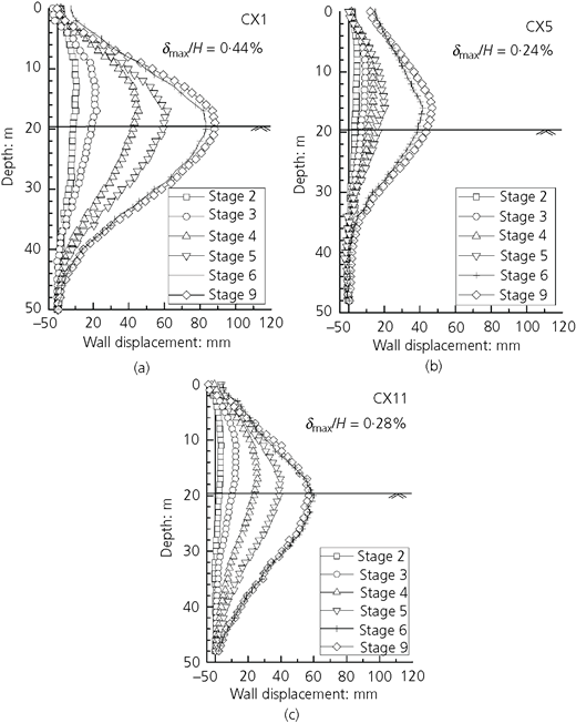
Figure 24 shows the lateral wall displacements behind the wall at each stage. The measured data at stage 9 when the second-level underground floor slab was constructed are also included for comparison. Before the bottom slab was cast, the lateral wall displacements increased significantly as the excavation proceeded. The wall deformed in a deep-seated profile, and the maximum wall displacement occurred near the formation level. Once the bottom slab was completed, additional lateral wall displacements were negligible or even reduced. As shown in this figure, the maximum wall displacements δ max fall in the range 0·24–0·58% H. The lateral wall displacement at CX5 is the smallest due to corner effects. Since diaphragm walls at CX11 are 1200 mm thick and offered relatively stiffer supports, the measured wall displacements are smaller than those at point CX1 where 1000 mm thick walls were used.
Bear in mind that the historic buildings were not underpinned until diaphragm walls and foundation piles had been constructed. As illustrated in Figure 25, the delicate unreinforced buildings settled as much as more than 25 mm just in the course of wall installation, contributing to about 50% of the final building settlement. After completion of underpinning work, the influence of excavation on the buildings was limited until it was excavated to the fifth level of strut. Building settlements increased significantly when the final 3 m thick soil was removed. Considering the short distance between underpinning piles and the excavation, the excavation-induced deformation may change stresses behind the wall and alter the shaft resistance along the piles. Not only the total settlement but also the differential settlement needs to be analysed to evaluate the building response. The maximum differential settlement was found to be 1/1800, and no obvious structural damages were observed.
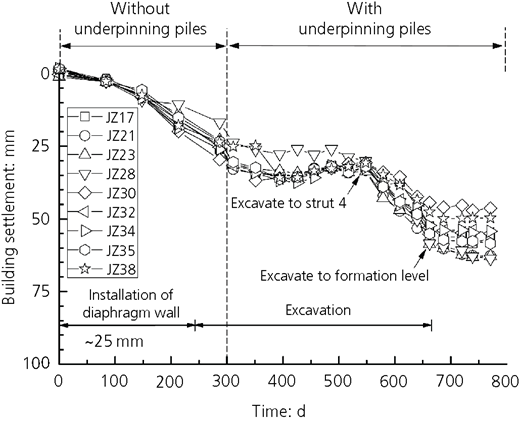
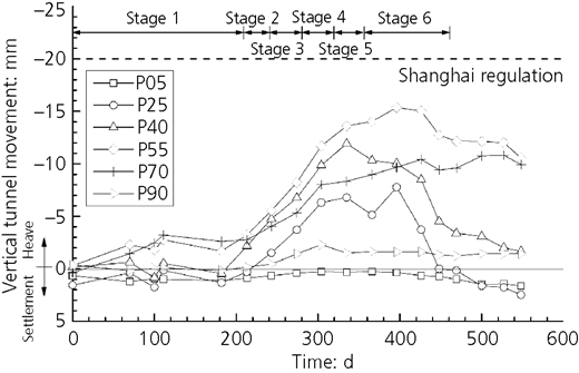
Figure 26 shows the development of tunnel movements with time. Since P05 was beyond the excavation while P90 was 42 m away from the excavation, the vertical tunnel movements due to excavation were less than 3 mm at the two locations. For other locations, tunnel linings continued to heave during the principal excavation period, from stage 2 to stage 6. It is postulated that the ground heave due to stress relief was dominant in the period and the soil behind the wall heaved, making the tunnel move upwards as well. The maximum tunnel heave was 15·5 mm. The structural integrity of the tunnels was protected well, and these operated smoothly throughout the excavation process.
Conclusions
Ground deformations due to excavation, and their effects on adjacent environment, are increasingly important as more underground construction is undertaken in urban areas. However, the influences on nearby existing buildings, tunnels, utilities and other structures are too often neglected. In Shanghai, excavations are categorised into three protection levels for engineering purposes, depending on types of adjacent environment as well as their distance away from the excavation. Deformation criteria associated with lateral wall displacements and ground surface settlements vary with protection levels.
Ground deformation control and protection of adjacent properties remain challenging for deep excavations in soft clays. Various types of protective measures have been commonly applied to control ground movements or increase the ability of adjacent structures to tolerate those movements in Shanghai. Those measures include, but are not limited to, the ground improvement technique, the top-down method, the zoned excavation technique and underpinning. Four relevant case histories in different urban settings have been successfully constructed, proving the aforementioned techniques to be effective in mitigating excavation-induced influences on nearby environment in Shanghai soft clays. The selection of the mitigating measures must be made with comprehensive considerations of geological conditions of the construction site, types of structures to be protected, adjacent environment conditions and so on. As the theory and practice of excavation develop, more innovative design and construction techniques are expected in the future.

