
Embankment dams can be damaged by internal erosion, which ultimately leads to failure. When internal erosion occurs, finer soil particles from the core soil are washed out. To restore the function of the core, injection grouting can be undertaken. Grouting the core of an embankment dam should be performed with a grout material with characteristics similar to those of the core soil, such as a low-mobility grout. This type of grout material has similarities to a fine-grained moraine core soil given its stiffness, but it has difficulties permeating the damaged core soil. A modified low-mobility grout material containing gravel, sand, limestone filler, bentonite, plasticiser, an air-release agent and water was tested in the laboratory with focus on permeation. Injection was done on differently sized aggregates. The impact of the paste-to-aggregate ratio, grout consistency, the maximum grain size of the grout material, the particle size distribution of the injected material and the injection method was tested. Higher paste-to-aggregate ratios, lower viscosity and lower yield strength of the grout material improved the permeation.
Notation
- D15
particle size at 15% of the total weight of aggregates in the grout material (mm)
- Dmax
maximum particle size of the grout material (mm)
- d15
particle size at 15% of the total weight of aggregates in the coarse-grained material (mm)
- dmax
maximum particle size of the coarse-grained material (mm)
- Ø
diameter (mm)
Introduction
In Sweden, there are about 190 hydropower dams with heights of over 15 m (Bernstone et al., 2009), 130 of which are hydropower embankment dams mostly built between 1940 and 1970. Swedish embankment dams are typically constructed with a central core of fine-grained glacial till, sand–gravel filters and shoulder zones. Over time, embankment dams might undergo internal erosion, which leads to excessive leakage and compromised dam safety. Because of this, efforts are made to extend the service lifetime of existing dams by repairing the dam body. According to the International Commission on Large Dams (ICOLD, 2017), three conditions must be fulfilled for internal erosion to occur: (a) a source of water and a seepage flow path; (b) an erodible material within the flow path inside the embankment dam; and (c) an unprotected open or unfiltered exit from which the eroded soil material can escape. If these three conditions occur, material from the core is transported away with the seepage. If internal erosion continues unhindered, it can lead to permanent damage to the core, which ultimately leads to a breach of the embankment dam. One type of internal erosion is suffusion. Suffusion occurs in widely graded or gap-graded soils when fines are flushed through pores formed by the coarser particles at an unaffected bulk volume (ICOLD, 2017). Only the coarsest particles of the widely graded or gap-graded soil remain in place (Khaksar Najafi and Eslami, 2015). Suffusion will gradually increase the hydraulic conductivity of the core and further increase the seepage through the dam. Reports of suffusion in embankment dams can be found in studies such as those by Lafleur et al. (1989), the Comité Français des Grands Barrages (CFGB, 1997), Stewart et al. (1998), Wolski et al. (2000), Fell et al. (2005) and Sjödahl et al. (2010).
To prevent internal erosion in a dam that results in a breach and depending on the seriousness of the damage, different types of measures can be employed, such as long-term, short-term and crisis measures (Bradley et al., 2007). Long-term measures involve new filters, new drains, cut-offs, dam toe berms, remediation injection grouting and relief wells. Short-term measures include not only modified dam operation strategies such as reservoir drawdown and reservoir restrictions but also measures such as remediation injection grouting, filters, drains, berms and relief wells. Crisis measures include emergency drawdown of reservoir, evacuation of downstream residents, and remediation injection grouting.
The main purpose of remediation injection grouting in the core of an embankment dam is to decrease the seepage rate by reducing the hydraulic conductivity of the core (Foster et al., 2000). Grouting should be done carefully to prevent excessive pore water pressures (Fell et al., 2005; Park and Oh, 2018). Cement-reinforced zones should be avoided since cracks and settlements can form due to different mechanical behaviours between the core soil and grouted zone (Lim et al., 2004). If grouting is chosen to remediate a core, the grouting method should always be chosen according to the damage type. In Sweden, compaction grouting (CG) and permeation grouting (PG) have been used for remedial injection grouting in embankment dams (Ekström et al., 2016). During CG, a stiff, high-viscosity, high-yield-strength, low-mobility grout (LMG) material is injected into the soil. The LMG material should have characteristics similar to those of the non-eroded core soil – that is, particle size distribution, bulk density, porosity, shear strength and hydraulic conductivity. During the injection, the LMG material does not mix with the soil into which it is injected. A reduction in hydraulic conductivity is achieved by the densification of the surrounding soil (Warner, 2004). If the core damage is caused by suffusion, CG will not be as effective since densification of a coarse-grained soil material will not decrease the hydraulic conductivity of the core soil enough to function properly (Lagerlund, 2022). Instead, PG can be performed. During PG, the grout material permeates the voids of the soil into which it is injected. The grout material for PG should therefore have a lower viscosity and yield strength compared with an LMG material used for CG. Usually, the grout material for PG is very fine graded to prevent plug formation (Eklund and Stille, 2008). Furthermore, the water content is higher compared with that of the LMG material to decrease its viscosity and yield strength.
Remedial injection grouting of an embankment dam exposed to suffusion requires the PG method. The grout material should have physical properties similar to those of the original core and should not contain cementitious materials. Hence, when remediating a core soil exposed to suffusion, the desired grout material characteristics should be those of an LMG material. Thus, permeation of LMG material into the voids of the coarse material is needed. Therefore, the use of an LMG material with improved permeation properties – for example, decreased viscosity and yield strength – should be of interest. In this study, an experimental LMG material without cement was tested in terms of permeation of coarse-grained soils (core soils damaged by suffusion) with a pilot-scale laboratory set-up. Permeation of the coarse-grained soils was evaluated in relation to the particle size distribution, viscosity and yield strength of the LMG material, as well as the pore sizes of the coarse-grained soils and the grouting method.
LMG material for embankment dams
When pumped, a grout material behaves as a fluid. A fluid is a material that is continuously deformed when exposed to shear stresses (Warner, 2004). The grout material – for example, LMG material – is a non-Newtonian fluid with both plastic viscosity and a yield strength. A non-Newtonian fluid has more solid-like properties at low stresses but flows at higher stresses. Compared with a Newtonian fluid such as water, a non-Newtonian fluid must be exposed to a certain amount of shear stress – that is, the applied stress must be higher than the yield strength of the fluid – before it can flow. During pumping of a grout material, its flow behaviour is governed either by hydrodynamic interactions or by friction between its particles (Yammine et al., 2008).
To increase the potential of the LMG material to be used in PG, its viscosity and yield strength must be decreased into a more water-like state since conventional LMG materials are very stiff with low slump values. After injection, the decreased viscosity and yield strength should slowly return to those of a conventional LMG material. To decrease the viscosity and yield strength in concretes, the following actions could be undertaken according to Wallevik and Wallevik (2011):
increase the water content
increase the amount of paste (cement and/or limestone filler + water)
include a superplasticiser (SP)
increase the air content.
An SP is an additive used in the concrete industry to make concrete less viscous and decrease its yield strength. When mixing sand with an insufficient amount of water, lumps of sand are created due to polarity bonds with water trapped inside. The inclusion of an SP breaks up these bonds and frees the trapped water. Consequently, the sand becomes more fluid-like at lower water contents.
Since neither higher water nor higher air contents are desired in an LMG material for embankment dams, there should be a possibility to decrease its viscosity and yield strength by increasing the amount of paste and to include an SP. The following factors were considered in this study when designing the LMG material, suitable for PG and tested in the laboratory.
The water content of the LMG material should be similar to the in situ water content of the core soil. Excessive amounts of water in the LMG material can lead to high pore pressures due to drainage (bleed) after its injection in the core. If the water content is too low, the LMG material will be difficult to pump.
The particle size distribution of the LMG material should be similar to that of the core soil. The amount of fines should be no less than 20 wt% (Vattenfall, 1988).
The LMG material should not have hardening properties. Cementitious materials should not be used due to their hardening properties. Instead, an inert limestone filler (calcium carbonate (CaCO3)) can be used. Limestone filler does not hydrate like cement and will thus not transform the grout material from a fluid into a solid body of concrete.
Materials and methods
Preparing for laboratory testing
The following assumptions, based on the literature study, regarding the LMG material used in this study were made before testing.
The water content should be kept at ≤12%.
Cement should not be used to avoid hardening properties. A limestone filler with a fines content of ∼60% and a D max = 0.5 mm was used instead. The limestone filler functioned as a paste material as well.
An SP was used to decrease the viscosity and yield strength of the LMG material.
Dry bentonite powder was used to prevent bleeding of the LMG material. Furthermore, the bentonite had an expanding effect on the grout material after injection.
An air-release agent was used to limit the amount of air absorbed during homogenisation, as it breaks up air bubbles into smaller bubbles. This enabled the air to dissipate more easily from the LMG material.
The factors tested in the laboratory included the following.
Two different D max values of the aggregates in the LMG material (4 and 2 mm) were needed. All aggregates were composed of natural, spherical particles.
Two different ratios of limestone filler to aggregate specific surface area (L/A) – namely, 1.4 and 1.7 – were also needed. In this study, instead of using the conventional cement-to-solid-ratio by weight, the ratio between the specific surface area of the limestone filler and the specific surface area of the aggregates was used. The specific surface area of limestone filler material was measured with the Blaine method (SS-EN 196-6:2019 (SIS, 2019a)), and the specific surface area of the aggregate was calculated from the particle size distribution of the aggregates in the LMG materials under the assumption that all grains were spherical.
Two different consistencies (viscosity and yield strength) were tested for each type of LMG material. This was achieved with an additive of either 4.5 or 5.0 wt% SP given the amount of water. The testing of consistency was done with a mini-slump flow test developed for cementitious pastes (Tan et al., 2017). The test was a fast, indirect test of the viscosity and yield strength of a fresh grout material. During the test, a steel ring 40 mm high (base Ø = 85 mm and top Ø = 75 mm) was filled with the LMG material and removed. The circular form of fresh LMG material then started to settle, and when viewed from above, its diameter increased until a final spread was reached. The diameter of the base of the LMG material was measured, as shown in Figure 1. A smaller diameter means a stiffer LMG material (higher yield strength), while a larger diameter means a more water-like LMG material (lower yield strength). The time to perform the test can also be measured. Shorter setting times of the fresh grout mean lower viscosity, while longer setting times mean higher viscosity. Measurement of time was not done during the tests.
Two different injection methods were tested – namely, slow (method 1) and fast (method 2). The two methods were chosen to investigate whether the flow velocity of the LMG material during injection affected the permeation.
Three different types of soils with fictive suffusion damages (coarse-grained material) were tested. These coarse-grained materials had d 15 = 35, 75 and 110 mm.
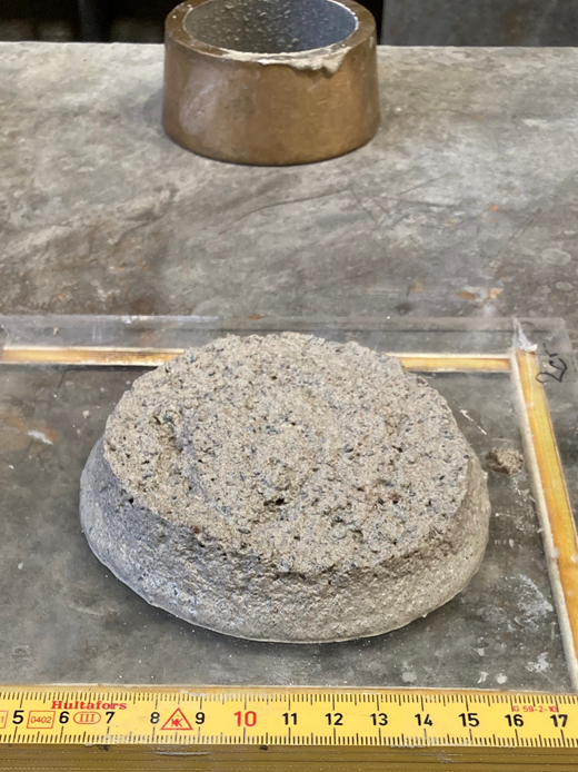
Mini-slump flow test. The measurement was done on the bottom diameter of the LMG material. Consistency in the figure is approximately 100 mm
Mini-slump flow test. The measurement was done on the bottom diameter of the LMG material. Consistency in the figure is approximately 100 mm
In total, 48 injection tests were done. All test combinations are shown in Table 1.
Test matrix for the injection tests
| Series | LMG material | Methodb | Coarse-grained material | ||
|---|---|---|---|---|---|
| L/A ratioa | D max: mm | Consistency: mm | d 15: mm | ||
| 1 | 1.4 | 4 | 100, 150 | 1 | 35, 75, 110 |
| 2 | 1.4 | 4 | 100, 150 | 2 | 35, 75, 110 |
| 3 | 1.4 | 2 | 100, 150 | 1 | 35, 75, 110 |
| 4 | 1.4 | 2 | 100, 150 | 2 | 35, 75, 110 |
| 5 | 1.7 | 4 | 100, 150 | 1 | 35, 75, 110 |
| 6 | 1.7 | 4 | 100, 150 | 2 | 35, 75, 110 |
| 7 | 1.7 | 2 | 100, 150 | 1 | 35, 75, 110 |
| 8 | 1.7 | 2 | 100, 150 | 2 | 35, 75, 110 |
Specific area of limestone filler (m2/kg)/specific area of aggregates (m2/kg)
1 = slow, 2 = fast
LMG material and damage design for the tests
The recipes for the four types of LMG materials tested are shown in Table 2. The two LMG materials with D max = 4 mm consisted of natural, rounded gravelly sand material with particle sizes ranging from 0 to 8 mm (0/8 mm) sieved through a 4 mm mesh prior to usage; limestone filler (product name K500); and natural, rounded sand with particle sizes ranging from 0 to 2 mm (0/2 mm). The two LMG materials with D max = 2 mm consisted of the same 0/8 mm gravelly sand as used for the D max = 4 mm LMG material but sieved through a 2 mm mesh; the 0/2 mm sand; and the limestone filler. The particle size distributions of the four LMG materials are shown in Figure 2. All LMG materials also contained tap water, SP (MasterGlenium ACE 45), an air-release agent (MasterCast 202) and bentonite powder (DantoCon Pure C). The water had a temperature of 8–10°C. The amounts of additives – namely, SP, air-release agent and bentonite powder – were added in relationship to the amount of water.
Recipes for the four LMG materials tested
| Material | D max = 4 mm, L/A = 1.4 | D max = 4 mm, L/A = 1.7 | D max = 2 mm, L/A = 1.4 | D max = 2 mm, L/A = 1.7 |
|---|---|---|---|---|
| 0/8 mm sieved gravel (D max 4 mm): wt% | 46 | 43 | ||
| 0/8 mm sieved gravel (D max 2 mm): wt% | 46 | 43 | ||
| 0/2 mm sand: wt% | 18 | 17 | 18 | 17 |
| K500 (calcium carbonate): wt% | 36 | 40 | 36 | 40 |
| Water:a wt% | 12 | 12 | 12 | 12 |
| SP:b wt% | 5.0, 4.5 | 5.0, 4.5 | 5.0, 4.5 | 5.0, 4.5 |
| Air-release agent:b wt% | 0.21 | 0.21 | 0.21 | 0.21 |
| Bentonite:b wt% | 3.06 | 3.06 | 3.06 | 3.06 |
| L/A | 1.4 | 1.7 | 1.4 | 1.7 |
| W/L | 0.33 | 0.30 | 0.33 | 0.30 |
| Content of fines (<0.063 mm): wt% | 25.0 | 27.5 | 26.5 | 29.0 |
wt% of all aggregates + limestone filler
wt% of water
Note: each of the four LMG materials was tested at two different consistencies. W/L, water-to-limestone filler-ratio
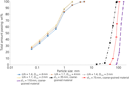
A total of three soils were used as a coarse-grained material to mimic soil exposed to suffusion with d 15 = 35, 75 and 110 mm. The coarse-grained materials were natural, rounded gravel and stone materials (Figure 3), with characterisation presented in Table 3.
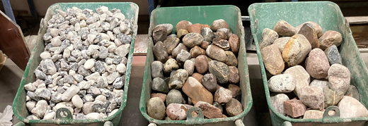
The three coarse-grained materials tested. From left to right: d 15 = 35, 75 and 110 mm
The three coarse-grained materials tested. From left to right: d 15 = 35, 75 and 110 mm
Characterisation of the coarse-grained material
| d 15: mm | 35 | 75 | 110 |
| d max: mm | 90 | 110 | 160 |
| d min: mm | 16 | 50 | 86 |
| Porosity | 0.45 | 0.46 | 0.48 |
| Bulk density: kg/m3 | 1460 | 1403 | 1350 |
Note: particle size distribution in Figure 2
Laboratory equipment
The pilot-scale laboratory equipment was designed to inject the LMG material in the same way as in real-life remediation injection on embankment dams – for example, vertical injection where the exit of the grout pipe was at the bottom of the damage, causing the grout material to rise through the damage (bottom-up). The equipment consisted of two parts: first, a 450 mm plexiglass cube with a wall thickness of 25 mm filled with a coarse-grained material and, second, a 320 mm dia. cylindrical steel container for LMG material connected to grout pipes from its bottom. The top of the cylindrical steel container had a lid that could be bolted shut, an inlet for compressed air, a pressure gauge and a safety valve enabling pressurised grouting. The bottom of the cylindrical steel container had a cone-shaped end, narrowing the 320 mm dia. cylindrical steel container to 75 mm over a length of 150 mm. At the bottom of the cone, a valve was installed and connected to a plexiglass pipe with a length of 375 mm and a diameter of 75 mm. This pipe was connected by a screw to a steel grout pipe with a length of 925 mm and a diameter of 75 mm. The exit of the steel pipe was 50 mm above the bottom of the plexiglass cube. The total pipeline length was 1300 mm. The set-up is shown in Figure 4.
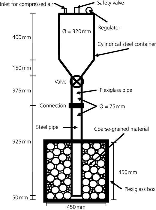
The plexiglass box was put on a scale with an accuracy of 50 g to measure LMG material uptake in real time during injection. The cylindrical steel container was lifted, so the connected grout pipes could run freely inside the coarse-grained material – that is, the weight of steel container and pipes did not affect the weight of the plexiglass box during injection.
Laboratory measurements
Measurements before and during each injection test are presented in Table 4.
Measurements performed before and during each test
| Coarse-grained material | LMG material | Injection procedure |
|---|---|---|
| Particle size distribution Bulk density (kg/m3) Porosity | Bulk density (kg/m3)a Air content (%)b Bleed and settlement (%)c Mini-slump flow (mm)d | Grout uptake (s/5 kg) Total grout uptake (kg) |
For each injection test, the time was started after the valve had been opened, when the first weight increase of the scale was noted. For each 5 kg weight added on the scale during each injection test, the time from start was registered.
Laboratory execution
The laboratory execution of each injection test was as follows.
The empty plexiglass box was placed on a scale, and then the coarse-grained material was placed inside the plexiglass box around a centrally placed grout pipe. The weight was measured before and after filling the plexiglass box. The weight of the grout pipe was deducted. After this, the plexiglass box was filled with water and weighed again. The water was then drained from the material, and grouting was directly performed.
The weight of the aggregates + limestone filler according to the recipes in Table 2 was measured. Compensation was done for its moisture content. The dry weight of aggregates + limestone filler was 60 kg for each batch, giving roughly 27 l of LMG material. The bentonite powder was added dry without pre-swelling.
The tap water was run for 2 min in all batches to achieve similar temperatures. Water was weighed, and the SP + air-release agent were added.
All aggregates + limestone filler was put in a pan mixer and homogenised for 5 min. Water and additives where then added, and the homogenisation proceeded for another 5 min. After a total time of 10 min, the LMG material was poured into a wheelbarrow.
The LMG material was kept in the wheelbarrow until the desired consistency of either 150 or 100 mm was reached.
The characteristics of the LMG material according to Table 4 were determined.
The LMG material was poured into the cylindrical steel container, the lid was fixed and the hose for compressed air was connected.
The cylindrical steel container was connected to the overhead crane, lifted in position and connected to the grout pipe in the plexiglass box. The cylindrical steel container + the pipe was elevated by 50 mm, so the exit of the pipe was 50 mm above the bottom of the plexiglass box.
Injection was done in either two ways.
Method 1 – slow injection. The flow of the LMG material through the pipes and into the coarse-grained material was governed only by the height and weight of the LMG material. When the flow was stopped, compressed air was added on top of the grout column inside the cylindrical steel container to restart the flow. When the flow stopped, the compressed air was evacuated from the cylindrical steel container so it would not affect the weighing of the plexiglass box. Additional compressed air was added in increments of 40 kPa – that is, 40 kPa during the first increment, 80 kPa during the second and so on up to a maximum pressure of 280 kPa. Note that the pressure was always reset to zero between each pressure increment.
Method 2 – fast injection. An extra amount of compressed air of 80 kPa was added before the injection test started. The flow velocity was governed by both the height and weight of the LMG material plus the compressed air.
Each injection test was ended when either the cylindrical steel container was empty or no more weight increase was noted from the scale. The documentation was done by taking photographs, and the equipment was cleaned.
Twenty-four hours after each injection test, the bleeding and settlement of the LMG material was measured.
Results and discussion
The results from the LMG material characterisation prior to injection are presented in Table 5. The bulk density varied between 2150 and 2200 kg/m3, and the air content between 2.3 and 4.3%. Bleeding never occurred after 24 h, and settlements were between 0.2 and 0.8%. The results from the L/A = 1.7 LMG materials were considered superior to the results from the L/A = 1.4 LMG materials – that is, with higher densities and lower air content or settlement.
Results from LMG material characterisation
| Series | Consistency: mm | Bulk density: kg/m3 | Dry density: kg/m3 | Air content: % | Bleed: % | Settlement: % |
|---|---|---|---|---|---|---|
| 1 | ∼100 | 2160 | 1929 | 4.1 | 0 | 0.7 |
| 2 | ∼150 | 2168 | 1934 | 3.7 | 0 | 0.5 |
| 3 | ∼100 | 2156 | 1925 | 4.3 | 0 | 0.6 |
| 4 | ∼150 | 2154 | 1923 | 4.3 | 0 | 0.8 |
| 5 | ∼100 | 2186 | 1952 | 2.9 | 0 | 0.4 |
| 6 | ∼150 | 2201 | 1965 | 2.3 | 0 | 0.2 |
| 7 | ∼100 | 2181 | 1947 | 3.1 | 0 | 0.4 |
| 8 | ∼150 | 2196 | 1960 | 2.5 | 0 | 0.3 |
General observations during the tests
The laboratory set-up worked well, but the cone-shaped end of the cylindrical steel container could cause blockage, particularly with the L/A = 1.4 LMG materials injected with method 1 before additional pressurisation was undertaken. Blockage never occurred when injecting with method 2. When opening the valve at the start of each test, the LMG material fell in chunks from the cylindrical steel container into the pipe. After a few seconds, the pipes were filled (∼5 l of LMG material). No air pockets were observed in the LMG material inside the pipe or in the voids of the coarse-grained material that had been grouted. The weight of LMG material needed to fill the pipes was always deducted from the presented LMG material uptake in the coarse-grained material. When the whole batch was injected during a test, roughly 25 l of LMG material had permeated the coarse-grained material. All test results are presented in a Mendeley data set (Lagerlund, 2023). Examples of what the coarse-grained material in the plexiglass box looked like after an injection test can be seen in Figure 5.
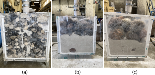
Plexiglass box after an injection test. LMG material D max = 4 mm; L/A = 1.7; injection method 2; coarse-grained material d 15 = (a) 35, (b) 75 and (c) 10 mm. All tests in the figure used the full batch of LMG material
Plexiglass box after an injection test. LMG material D max = 4 mm; L/A = 1.7; injection method 2; coarse-grained material d 15 = (a) 35, (b) 75 and (c) 10 mm. All tests in the figure used the full batch of LMG material
Influence of paste
The influence of the amount of paste in the LMG material on the permeation can be seen in Table 6. The presented results are from testing with method 1 before the stepwise pressure increase. The presented values are the total LMG material uptake expressed in litres when injecting the three different coarse-grained materials.
Influence of the L/A ratio on the LMG material permeation using method 1
| LMG material | Coarse-grained material | Permeation: l | |||
|---|---|---|---|---|---|
| Consistency =100 mm | Consistency =150 mm | ||||
| D max: mm | d 15: mm | L/A = 1.4 | L/A = 1.7 | L/A = 1.4 | L/A = 1.7 |
| 2 | 35 | 0.2 | 2.3 | 0.0 | 3.7 |
| 2 | 75 | 1.7 | 6.9 | 2.0 | 25.0a |
| 2 | 110 | 2.4 | 19.0 | 3.2 | 25.4a |
| 4 | 35 | 0.6 | 5.9 | 1.2 | 6.7 |
| 4 | 75 | 3.5 | 21.4 | 4.7 | 25.0a |
| 4 | 110 | 16.2 | 25.1a | 23.4 | 25.6a |
No LMG material left in the cylindrical steel container
A higher L/A ratio improved the permeation. The aggregates (sand and/or gravel) in the LMG material had a specific surface area and pore volume. The paste (limestone filler + water) then ideally filled this pore volume of the aggregates, diminishing the friction and lubricating the LMG material. The higher the specific surface area of the aggregates, the more paste is needed (Svensk Byggtjänst, 2017). However, if the L/A ratio is too high, the LMG material will become more viscous. This means that every unique LMG material should have its own unique paste optimum. Since only two L/A values were tested, it could not be determined whether an L/A > 1.7 would give an even better LMG material in terms of permeation.
Influence of the injection method
The influence of the injection method on the permeation of LMG material can be seen in Table 7. Only the results from the tests with a consistency of ∼100 mm were shown since the results from tests with a consistency of ∼150 mm were similar. Using method 2 greatly improved the permeation, and the full batch of LMG material with L/A = 1.7 was used during injection of all three types of coarse-grained materials.
Influence of the injection method on the LMG material permeation
| LMG material | Coarse-grained material | Permeation: l | |||
|---|---|---|---|---|---|
| L/A = 1.4 | L/A = 1.7 | ||||
| D max: mm | d 15: mm | Method 1 | Method 2 | Method 1 | Method 2 |
| 2 | 35 | 0.2 | 2.9 | 2.3 | 25.0a |
| 2 | 75 | 1.7 | 13.4 | 6.9 | 24.3b |
| 2 | 110 | 2.4 | 25.1a | 19.0 | 25.1a |
| 4 | 35 | 0.6 | 3.3 | 5.9 | 25.5a |
| 4 | 75 | 3.5 | 20.0 | 21.4 | 25.0a |
| 4 | 110 | 16.2 | 24.5a | 25.1a | 25.3a |
No LMG material left in the cylindrical steel container
Some LMG material stuck on the inside wall of the cylindrical steel container
Note: consistency = 100 mm
It should be noted that during method 1, the increase in extra pressure applied on the LMG material after the first initial stop was ineffective. None to very small amounts of LMG material were injected during the stepwise pressure increase. No heave of the coarse-grained material in the plexiglass box was ever observed during method 1 but it did occur during method 2 when injecting the coarse-grained material with d 15 = 35 and 75 mm at the very end of the test. From a theoretical point of view, a heave of the coarse-grained material should have occurred during each test since the used injection pressures exceeded the pressures given by the weight of the coarse-grained material in the plexiglass box. These observations suggested that the pressure form the LMG material was not transferred to the coarse-grained material, but only through the paste material, as described by Alexandridis and Gardner (1981).
Furthermore, the side-walls of the plexiglass box should have been pushed outwards due to the injection pressure. It was, however, noted that during the stepwise pressure increase, the weight on the scale increased proportionally to the amount of pressure used. When the pressure was removed from the cylindrical steel container, the weight on the scale went down. This implied that most of the injection pressure was directed straight down and not sideways/upwards when the stepwise pressure increase was applied. This behaviour was particularly evident for LMG materials with a consistency of ∼100 mm.
Finally, pressure bleed was experienced for both LMG material types (L/A =1.4 and L/A = 1.7) when pressures >197 kPa were applied (method 1 only). Pressure bleed was much more apparent for grout L/A = 1.4. Additionally, it could be observed through the plexiglass part of the pipe that at higher pressures, water was moving independently through the pore structure of the LMG material. This happened only for LMG materials with L/A = 1.4.
Influence of LMG material consistency
The influence of how the LMG material consistency affected the permeation of LMG material can be seen in Table 8. Only results from tests with method 1 before the stepwise pressure increase are presented. Results when using method 2 are similar, but the differences are much smaller.
Influence of consistency on the LMG material permeation using method 1
| LMG material | Coarse-grained material | Permeation: l | |||
|---|---|---|---|---|---|
| L/A = 1.4 | L/A = 1.7 | ||||
| D max: mm | d 15: mm | 100 mm | 150 mm | 100 mm | 150 mm |
| 2 | 35 | 0.2 | 0.0 | 2.3 | 3.7 |
| 2 | 75 | 1.7 | 2.0 | 6.9 | 25.0a |
| 2 | 110 | 2.4 | 3.2 | 19.0 | 25.4a |
| 4 | 35 | 0.6 | 1.2 | 5.9 | 6.7 |
| 4 | 75 | 3.5 | 4.7 | 21.4 | 25.0a |
| 4 | 110 | 16.2 | 23.4 | 25.1a | 25.6a |
No LMG material left in the cylindrical steel container
The permeation improved when the consistency of the LMG material was higher – for example, consistency = 150 mm. The reason for this is that at a higher consistency, the LMG material has a lower viscosity and yield strength. This means that the LMG material will not only have a lower resistance to flow but will also more easily permeate smaller pores (Hässler, 1991).
It was also noted during the tests that LMG materials with consistency = 100 mm tended to permeate the coarse-grained material in a more upward direction along the grout pipe. LMG materials with consistency = 150 mm permeated the coarse-grained material in a more horizontal direction (horizontal phreatic surface), as shown in Figure 6.
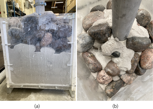
Appearance of the LMG material after the injection test: (a) consistency ≈ 150 mm (25.0 l injected), (b) consistency ≈ 100 mm (21.4 l injected). Coarse-grained material with d 15 = 75 mm
Appearance of the LMG material after the injection test: (a) consistency ≈ 150 mm (25.0 l injected), (b) consistency ≈ 100 mm (21.4 l injected). Coarse-grained material with d 15 = 75 mm
This implies that when grouting a horizontally orientated damaged zone in an embankment dam, the LMG material should have a higher consistency. However, grouting a vertically orientated damage should be done with LMG materials with lower consistencies. This furthermore implies that horizontal and ultimately upward directed stresses induced by injection pressures should decrease if the LMG material consistency is decreased. Higher injection pressures could therefore possibly be used when grouting an embankment dam with a low-consistency LMG material without risking heave.
Influence of the maximum particle size of the grout
The influence of how the D max of the LMG material affected the permeation can be seen in Table 9. With a D max = 4 mm, more LMG material permeated the coarse-grained material compared with D max = 2 mm. The penetrability of a grout material is explained by its rheological behaviour and its filtration tendency (Eklund and Stille, 2008). According to Eriksson (2002) and Hässler (1991), yield strength is the most important rheological factor for predicting penetration depth, while viscosity mainly affects the velocity of a grout material during injection. Filtration tendency describes the ability of a grout material to form a plug. Filtration tendency can be evaluated from the ratio between the D max of the grout and the aperture width to be grouted. According to Bergman et al. (1970), plug formation will occur unless the aperture is at least three times larger than the D max of the grout material.
Influence of D max on the LMG material permeation using method 1
| LMG material | Coarse-grained material | Permeation: l | |||
|---|---|---|---|---|---|
| L/A = 1.4 | L/A = 1.7 | ||||
| Consistency: mm | d 15: mm | D max = 2 mm | D max = 4 mm | D max = 2 mm | D max = 4 mm |
| 100 | 35 | 0.2 | 0.6 | 2.3 | 5.9 |
| 100 | 75 | 1.7 | 3.5 | 6.9 | 21.4 |
| 100 | 110 | 2.4 | 16.2 | 19.0 | 25.1a |
| 150 | 35 | 0.0 | 1.2 | 3.7 | 6.7 |
| 150 | 75 | 2.0 | 4.7 | 25.0a | 25.0a |
| 150 | 110 | 3.2 | 23.4 | 25.4a | 25.6a |
No LMG material left in the cylindrical steel container
Two-stage concrete is a type of concrete where the coarser-grained aggregates are pre-placed and compacted in a formwork and then injected with a cementitious paste. There are distinct similarities between applying two-stage concrete and the injection tests done in this study. There is no consensus regarding the ratio between aggregate and grout material particle sizes to achieve permeation. The following ratios are proposed in the literature:
Svensk Byggtjänst (1997): d 15/D max ≥ 14
Lindvall (2012): d min/D max ≥ 8–10
Awal (1984): d min/D max ≥ 10
ACI Committee 304 (1991: p. 5): ‘The minimum size of coarse aggregate determines the void dimensions through which the grout material must pass’
Abdelgader (1996) emphasises the rheology of the grout material – for example, lower yield strength gives better permeation.
The least favourable test set-up, from a filtration tendency point of view, was when the LMG material with D max = 4 mm was injected into the coarse-grained material with d min = 16 mm (d 15 = 35 mm). This meant that injection was performed at d min/D max = 4, which was too high to cause any plug formation. Furthermore, applying the theories from two-stage concrete, the least favourable conditions during testing was d 15/D max = 8.75 or d min/D max = 4 where permeation was achieved when injecting with method 2. Permeation was therefore achieved at lower ratios than that which was recommended in the literature. The differences in permeation between the two LMG materials (D max = 2 or 4 mm) according to Table 9 should therefore most likely be explained by their different yield strengths. The used aggregates in the LMG materials were made from the same 0/8 mm gravel but sieved to either a D max of 2 or 4 mm. This meant that the D max = 2 mm LMG material had a higher proportion of finer aggregates, which would slightly lower its L/A ratio compared with that of the D max = 4 mm LMG material. Consequently, the D max = 2 mm LMG material should have a higher viscosity and yield strength. Measurements of the rheological properties with a ConTec BML viscometer, designed for self-compacting concretes, of all the tested L/A = 1.7 LMG materials were therefore performed. As seen in Table 10, viscosity was higher for the LMG material with D max = 2 mm. Yield strength was higher only at a consistency of 100 mm.
Influence of the particle size of the coarse-grained material
The influence of how the particle sizes of the coarse-grained materials affected the permeation can be seen in Table 11.
Influence of the particle size of the coarse-grained material on the LMG material permeation using method 1
| LMG material | Coarse-grained material | Permeation: l | |||||
|---|---|---|---|---|---|---|---|
| Consistency = 100 mm | Consistency = 150 mm | ||||||
| L/A | D max: mm | d 15 = 35 mm | d 15 = 75 mm | d 15 = 110 mm | d 15 = 35 mm | d 15 = 75 mm | d 15 = 110 mm |
| 1.4 | 2 | 0.2 | 1.7 | 2.4 | 0.0 | 2.0 | 3.2 |
| 1.4 | 4 | 0.6 | 3.5 | 16.2 | 1.2 | 4.7 | 23.4 |
| 1.7 | 2 | 2.3 | 6.9 | 19.0 | 3.7 | 25.0a | 25.4a |
| 1.7 | 4 | 5.9 | 21.4 | 25.1a | 6.7 | 25.0a | 25.6a |
No LMG material left in the cylindrical steel container
The results showed that permeation was improved when the material in the plexiglass box was more coarse grained. With increased particle sizes, both voids and apertures became larger, enabling easier permeation. Additionally, the amount of contact points between grains were reduced in a more coarse-grained material, and at a contact point, the aperture width is zero – that is, no LMG material could pass it. A less coarse-grained material would furthermore have a higher specific area. If the LMG material would be injected in a coarse-grained material with a higher specific area, the pressure loss would be greater compared with that of injection of a grout into a coarse-grained material with a lower specific area. Uplift of the coarse-grained material was experienced when injecting with method 2 in the d 15 = 35 mm material. On a final note, the LMG material had a lower tendency to permeate the coarse-grained material horizontally (towards the side-walls of the plexiglass box), as the particle size of the coarse-grained materials was lower.
Conclusions
A higher amount of paste in the LMG material (1.7 against 1.4) greatly improved the permeation. The mean value of the improvement for all tests was about five to seven times. Injecting with an extra 80 kPa (method 2) from the start improved the permeation of the grout L/A = 1.4. If the flow of LMG material were stopped during injection (method 1), it would be difficult to restart even if the pressure to be used would exceed the pressure used in method 2. A higher consistency measurement of the LMG material (150 mm compared with 100 mm) improved the permeation. A higher Dmax of the LMG material (4 mm compared with 2 mm) improved the permeation. This difference was most probably caused by a higher yield strength/viscosity in the Dmax = 2 mm LMG material compared with that in the Dmax = 4 mm LMG material. Injection of the least coarse-grained material (d15 = 35 mm) caused an uplift when method 2 was used. Furthermore, the injected LMG material tended to spread in a more horizontal direction during the injection of the more coarse-grained materials (d15 = 75 and 110 mm). Of all the tested grout combinations, the grout from series 5 and 6 (L/A = 1.7, Dmax = 4 mm) had the highest potential as permeable LMG to be used as remedial grout in embankment dams damaged by suffusion.
The zone of grouted coarse-grained material will be gap graded and, as such, it is susceptible to internal erosion. It should therefore be clarified that this study only had the aim of investigating the possibility of using an SP in an LMG material, enabling its use for PG in core soils exposed to suffusion. Further development of this type of LMG material is needed in terms of longevity.
Finally, the shear strength and hydraulic conductivity of the grouted zone were outside the scope of this study but would likely be investigated in a separate paper.
Acknowledgements
The authors would like to acknowledge Svenskt Vattenkraftcentrum (SVC), Energiforsk AB, Luleå University of Technology and Vattenfall AB for the funding of this work. The authors give special thanks to Professor Emeritus Anders Sellgren at Luleå University of Technology for all the discussions regarding pumping of slurries and paste and Louise Andersson, RISE Institute, for help with rheological measurements.
